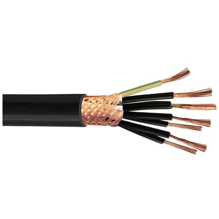
Specify the wrong cable type on a purchase order and you might not find out until commissioning day — when the installation crew is standing around, the project is behind schedule, and you’re looking at a mismatched insulation rating or an undersized conductor that won’t pass inspection. That’s a fixable problem if you catch it early. If you don’t, the consequences range from repetitive nuisance tripping on an overloaded circuit all the way to a smoldering junction box and an insurance conversation nobody wants to have. The global wire and cable market sits somewhere around USD 225 billion and is tracking toward USD 300 billion by 2030, which tells you something about how fundamental this material is — but market size doesn’t help you when you’re trying to decide between an armored power cable and a shielded instrumentation cable for a specific run in a wet, high-vibration environment.
Cable wire divides into several major categories based on construction and application: power cables (for transmitting electrical energy at low, medium, or high voltage), control and instrumentation cables (for signals and process control circuits), data and communication cables (structured cabling, fiber optic, industrial Ethernet), specialty cables (fire-resistant, mining, submarine, offshore), and flexible/winding wires. Each type is defined by its conductor material and class, insulation system, shielding, and outer jacket — all selected to match the voltage, current, mechanical stress, and environmental exposure of the installation.
What makes this more complicated than it looks is that the same physical location in a plant might need three or four of those categories running in parallel trays, each with different standards, bend radius limits, and procurement lead times. Copper’s resistivity of 1.72 × 10⁻⁸ Ω·m versus aluminum’s 2.82 × 10⁻⁸ Ω·m — roughly a 64% gap — already forces different conductor sizing decisions before you’ve even opened a catalog. The sections below work through each cable type the way an engineer actually needs to think about them: construction, ratings, where they belong, and where they definitely don’t.
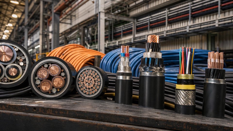
Power Cables: Low, Medium, and High Voltage Variants and Their Core Structural Differences
Power cables are not a single product category — they’re a family of engineered systems where voltage class, conductor geometry, insulation chemistry, and mechanical protection all interact. Specify the wrong combination and you’re looking at premature insulation breakdown, field failures during commissioning, or a procurement rejection at the customer’s incoming inspection. Getting it right starts with understanding how the tiers are actually defined and what structural decisions each tier demands.
Voltage Class Definitions and Where Each Tier Actually Shows Up
Low voltage (LV) cables cover up to 1 kV. This is the workhorse tier — building distribution boards, industrial motor feeders, lighting circuits, residential service entrances. The structural demands here are moderate: the insulation wall thickness is relatively thin, and the main design concerns are current-carrying capacity, mechanical durability, and flame performance.
Medium voltage (MV) runs from 1 kV up to 35 kV. Substation feeders, utility distribution networks, large industrial plants with 6 kV or 11 kV bus systems — this is where you encounter it most. At these voltages, electric field management becomes critical, and cables must include a semiconducting screen over the insulation and a metallic screen or concentric neutral to prevent field concentration at any irregularity in the insulation surface. Ignore this and partial discharge erodes the insulation from the inside over months or years, with no visible warning until the cable fails hard.
High voltage (HV) starts above 35 kV and extends through the transmission range — 66 kV, 110 kV, 220 kV, and beyond. These are utility-grade transmission and sub-transmission circuits. Structural complexity increases substantially: thicker XLPE walls, extruded semiconductor layers on both conductor and insulation surfaces, metallic screens designed to carry fault current, and often a longitudinally water-blocked design for buried or submarine runs.
Conductor Choices: Copper vs. Aluminum, Solid vs. Stranded
Copper’s resistivity sits at 1.72 × 10⁻⁸ Ω·m; aluminum’s is 2.82 × 10⁻⁸ Ω·m — roughly 64% higher. In practice that means an aluminum conductor needs to be about 1.5 to 1.6 cross-section classes larger than copper to carry the same current. On a 500 mm² run, that matters for conduit sizing and termination hardware. Aluminum is lighter — typically 50–60% less mass per meter for equivalent ampacity — and noticeably cheaper per kilogram, which on long LV distribution runs in the Middle East or parts of Africa makes it the default choice. Code acceptance varies though: some European and North American markets restrict aluminum in certain building wiring applications, so always check the local standard before locking in a conductor material with your client.
For conductor form, IEC 60228 Class 1 and Class 2 (solid and stranded) cover most fixed power installations. Flexible Classes 5 and 6 are for equipment connections and trailing cables where repeated bending occurs. Using a Class 2 stranded cable where Class 5 is needed — on a machine tool cable carrier, for example — leads to conductor fatigue cracking within a few thousand flex cycles.
Insulation: PVC, XLPE, and EPR
PVC dominates general LV applications. It’s inexpensive, easy to process, and performs adequately where continuous conductor temperatures stay at or below 70°C. Its limitations show at elevated temperatures and in environments with significant UV exposure or hydrocarbon contact.
XLPE (cross-linked polyethylene) is the preferred insulation for MV and HV cables, and increasingly for higher-rated LV cables too. The cross-linking process gives it a continuous operating temperature of 90°C — meaningfully higher than PVC — and a short-circuit temperature rating around 250°C, which matters a lot when you’re sizing cables for fault current withstand. XLPE also has lower dielectric losses, which on long HV runs translates to measurable efficiency gains.
EPR (ethylene propylene rubber) is the choice for flexible MV cables in mining, offshore, and process plant environments. It tolerates tight bending radii, handles wide temperature swings without cracking, and performs well in wet or chemically aggressive surroundings. It costs more than XLPE and is less common in static grid installations, but for trailing mine cables or subsea umbilicals, the flexibility and toughness justify it.
Armoring Options and When They’re Specified
Steel wire armor (SWA) provides robust mechanical protection and is the standard specification for direct-buried LV and MV cables in most markets. The individual wires also carry fault current back to the source, which is a functional requirement in many distribution designs, not just a mechanical nicety.
Steel tape armor (STA) is lighter and cheaper but offers less crush resistance. It shows up in cable tray and duct installations where the mechanical threat is modest.
Aluminum wire armor (AWA) is specified on single-core cables where steel would create induced circulating currents and unacceptable losses. Single-core HV cables almost always use AWA or a similar non-magnetic armor for exactly this reason.
Jinda's power cable range covers voltage ratings from 0.6/1 kV through HV classes, with conductor cross-sections from 1.5 mm² up to 500 mm² and beyond, manufactured to IEC 60502 and GB/T 12706 standards.True
These specifications align with standard industry practice for a mid-to-large cable manufacturer serving international utility and industrial markets; IEC 60502 covers extruded solid dielectric insulated power cables for voltages from 1 kV to 30 kV, and GB/T 12706 is the Chinese national equivalent widely accepted in international tenders.
For procurement teams evaluating supply options, the combination of IEC 60502 and GB/T 12706 compliance is meaningful — it means third-party type test reports are available and the cable’s construction has been validated against a recognized standard, not just a factory spec sheet.
Control Cables: Multi-Core Designs for Automation, Switchgear, and Process Instrumentation Panels
Control cables get misapplied more often than most engineers would like to admit. The confusion usually comes from treating them as simply “smaller power cables,” which they are not — at least not functionally. A control cable’s job is to carry command signals and low-power switching currents, typically well under 5 A, between PLCs, relay panels, motor control centers, and field instruments like pressure transmitters or solenoid valve pilots. They don’t transfer bulk energy from source to load. Getting that distinction wrong in a panel design can mean nuisance trips, damaged signal circuits, or — in a VFD-heavy environment — enough induced noise to make an entire process control loop unstable.
What Actually Differentiates Control Cables from Power Cables
The conductor cross-section tells part of the story. Control cables typically run from 0.5 mm² to 4 mm² per core, since the current levels don’t demand anything larger. What matters more is the combination of core count, shielding architecture, and jacket chemistry — none of which matter nearly as much in a standard power cable.
Core counts range from 2-core pairs up to 61-core bundles, and that upper range is genuinely useful in dense automation rooms. A 37-core or 61-core cable run along a single cable tray can replace a dozen smaller runs between a marshalling cabinet and a DCS rack, which simplifies conduit fill calculations, reduces tray congestion, and cuts installation labor meaningfully — typically 20–40% fewer conduit entries at the panel, depending on how the wiring is grouped. The tradeoff is that fault isolation gets more complex, so clear documentation and consistent core identification become non-negotiable.
Shielding: Not One-Size-Fits-All
Shielding choice is where engineers often under-specify, especially in retrofit projects where the EMI environment wasn’t well characterized originally. Unshielded control cable works acceptably in clean electrical rooms with no high-frequency switching equipment nearby. The moment you introduce VFDs, servo drives, or switchgear with fast-switching thyristors into the picture, you need shielding — and the right kind.
Individually shielded pairs (ISP) protect each signal pair independently, which is the correct approach for multi-channel analog instrumentation where crosstalk between signal pairs would corrupt 4–20 mA readings. Overall foil shielding (with a drain wire) provides decent high-frequency rejection at lower cost and suits digital signal buses in moderate-noise environments. An overall braid shield offers lower shield impedance and handles lower-frequency interference more effectively but adds weight and some rigidity. Combined foil-plus-braid constructions give you both — the foil blocks high-frequency noise while the braid provides a robust low-impedance ground path — and this is the configuration I’d specify for a control cable running parallel to VFD output cables for any meaningful distance, say more than 10–15 meters.
Insulation and Jacket Materials for the Real Environment
PVC insulation and jackets remain the default for general indoor installations — cost-effective, widely available, and adequate for temperatures up to roughly 70°C. In switchrooms or data center electrical rooms where fire load and toxic smoke are genuine concerns, LSZH (low-smoke zero-halogen) jacket compounds are the correct choice and are increasingly mandated by building codes in Europe, the Middle East, and parts of Southeast Asia. LSZH cables typically run 15–30% higher in unit cost compared to equivalent PVC versions, but that premium becomes irrelevant against the life-safety and evacuation implications of a cable fire in an occupied building.
Machine tool environments introduce a different problem: hydraulic oils, coolants, and solvent-based cutting fluids that attack standard PVC over time, causing jacket cracking and eventual insulation failure. PUR (polyurethane) outer jackets resist these fluids well and handle repeated flexing in drag-chain applications where a rigid cable would fatigue and fail within months.
Core Identification and Why It Reduces Commissioning Errors
IEC 60446 and DIN VDE 0293 define color coding and sequential numbering conventions for multi-core control cables, and following them consistently is one of those unglamorous practices that pays back every time a panel gets extended or faulted. Sequential core numbering — printed directly on the insulation rather than relying only on color in cables above 5 cores — means a technician can trace any wire in a 24-core bundle without an ohmmeter. In practice, plants that deviate from standard numbering during panel fabrication often spend disproportionate time during commissioning just confirming which wire is which.
Control cables rated 300/500 V are suitable for use in power distribution circuits carrying motor starting currents.False
Control cables are rated for command signal and low-power switching duty, typically ≤5 A. Applying them to motor starting or power distribution circuits exceeds their current-carrying design intent and can cause insulation thermal degradation or fire.
Installation Practices That Actually Matter
Bend radius for control cables is typically specified at 6–10× the overall cable diameter for fixed installations, and pulling tension limits in conduit runs depend on conductor cross-section and fill — ignoring these limits during installation pulls the conductors tight against insulation and damages shielding continuity. In cable tray runs, control cables should ideally be separated from power cables by at least 200–300 mm, or routed in dedicated trays, to minimize inductive coupling. That separation is often the first thing compromised on a tight site, and it’s usually the first thing the commissioning team regrets.
Jinda’s control cable range covers rated voltages of 300/500 V and 450/750 V, with conductor sizes from 0.5 mm² to 6 mm² and core counts up to 61. Shielding options include overall foil, overall braid, individually shielded pairs, and foil-plus-braid combinations. LSZH-jacketed variants are available for switchrooms, transit infrastructure, and building automation projects where halogen-free requirements apply. For international procurement projects requiring third-party certification or specific national approvals, Jinda’s technical team can confirm applicable standard compliance before order confirmation — which matters more than most buyers realize when cables are clearing customs for a regulated infrastructure project.
Instrumentation and Signal Cables: Precision Transmission for Sensors, Analyzers, and SCADA Systems
Instrumentation cables occupy a different design space than control cables, even though the two are often confused on procurement documents. The distinction matters. A control cable carries switching signals at modest voltage levels where a few millivolts of noise rarely causes a problem. An instrumentation cable may carry a thermocouple output of 10–50 mV across 300 m of cable tray, or a 4–20 mA loop where a 1 mA error translates directly into a process measurement error that can trip a safety interlock or send a PID controller hunting. The electrical tolerances are tighter because the consequences of interference are immediate and measurable.
Why Capacitance and Geometry Determine Signal Integrity
Capacitive coupling between adjacent conductors is the main enemy of low-level analog signals. Poorly constructed cables with high mutual capacitance — typically anything above roughly 120–160 pF/m, depending on insulation material and geometry — attenuate HART protocol signals, which ride at 1,200 and 2,200 Hz superimposed on a 4–20 mA loop. If the cable capacitance is too high, HART communication simply fails at distances over a few hundred meters. For thermocouple circuits, the issue is slightly different: it is electromagnetic induction from nearby power cables that introduces 50/60 Hz noise into the measurement, distorting the millivolt signal at the instrument input.
Twisted pair geometry addresses this directly. Twisting causes successive half-loops to cancel magnetically induced voltages. Standard industrial instrumentation cables use twist rates in the range of 25–60 turns per meter, with tighter twisting used for more noise-sensitive applications. Twisted triplets — three conductors twisted together — are used for RTD circuits where a third wire compensates for lead resistance.
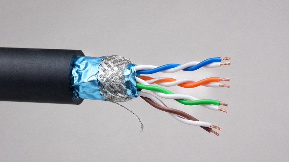
Individual Pair Shielding Versus Overall Shielding
In a multi-pair cable, individual pair shields (each twisted pair wrapped in its own foil and drain wire) prevent cross-talk between pairs. This matters enormously in a cable running 20 or more pairs — without individual shields, a thermocouple circuit in pair 3 can pick up induced voltage from the 4–20 mA signal in pair 7. An overall shield alone will not stop this. In practice, the industry standard for serious process instrumentation is individual pair shielding plus an overall shield, sometimes called combination or composite shielding. Overall-shield-only designs are acceptable only for low-density cables in relatively clean electromagnetic environments — a packaging line, say, not a refinery.
Fieldbus and Impedance-Controlled Cables
PROFIBUS DP requires a cable with characteristic impedance of 135–165 Ω and a specific capacitance below 30 pF/m for Type A cable, which supports segment lengths up to around 1,200 m at 1.5 Mbit/s. Use a standard instrumentation cable instead and you will see reflections on the bus, intermittent communication faults, and devices that drop off at random intervals — typically blamed first on the PLC, not the cable. Foundation Fieldbus H1 specifies 100 Ω ±20%, and DeviceNet similarly controls impedance at 121 Ω. These are not interchangeable. Always verify the cable’s datasheet against the fieldbus specification, not just the conductor cross-section.
Thermocouple Extension and Compensating Cables
Using a standard copper cable instead of a matched thermocouple extension cable introduces a parasitic thermoelectric junction that corrupts temperature readings throughout the cable run.True
Any dissimilar metal junction in a thermocouple circuit generates its own EMF per the Seebeck effect. IEC 60584 specifies the conductor alloy tolerances for each thermocouple type (K, J, T, E, R, S, B) precisely to prevent this error.
Type K extension cable, for example, uses NiCr/NiAl conductors matched to the thermocouple alloy. Substituting copper introduces an error that varies with ambient temperature along the cable run — impossible to correct in software because the error is not constant. The IEC 60584 standard governs allowable tolerance classes; Class 1 cables are used for precision applications, Class 2 for general process measurement. Color coding differs between IEC and ANSI/ISA conventions, which causes real problems on retrofit projects where old and new cables are mixed.
Fire-Safe Variants for Petrochemical and Offshore Use
On offshore platforms and in petrochemical plants, instrumentation cables must also meet fire performance requirements. IEC 60332-3 governs flame propagation in cable bundles; IEC 61034 covers smoke density. Low-smoke halogen-free (LSHF) insulation and jacket compounds are standard in these environments. Some applications also require armoring — typically with a single or double layer of steel wire armor (SWA) for mechanical protection in cable trays subject to foot traffic or for direct burial runs between field instruments and marshalling cabinets.
What Jinda Supplies for Instrumentation Applications
Jinda’s instrumentation cable range runs from 1-pair to 50-plus-pair configurations, covering both individually screened and combination-screened constructions. Belden-equivalent constructions — matching the electrical parameters and physical dimensions of Belden 9501, 9502, and comparable types — are available for retrofit projects where the original specification was written around those references. Thermocouple extension cables for Types K, J, T, E, R, S, and B are manufactured to IEC 60584, with LSHF jacketing and armored options for offshore and hazardous-area projects.
Building Wire and Wiring Cables: NM-B, THHN, NYM, and H07V-U Types Decoded
Walk into any electrical wholesale counter in three different countries and you’ll hear three different names for what is essentially the same job: getting power from a breaker panel to a receptacle, a light fixture, or a small motor. The naming confusion is real, and it costs projects money when the wrong product ships.
NM-B (Nonmetallic Sheathed Cable)
NM-B — sold generically under the Romex trade name in the US — is a grouped cable: two or three insulated conductors plus a bare equipment ground, all wrapped in a thermoplastic outer jacket. The conductors are rated 90°C at the insulation, but NEC Table 310.15 forces you to derate to the 60°C column for ampacity calculations in NM-B because the jacket traps heat. That means a 12 AWG NM-B circuit is limited to 20 A, not the 25 A its insulation could theoretically handle in free air.
It is permitted only in dry, protected, concealed residential and light commercial locations. No wet locations, no exposed runs, no embedment in concrete, no use as a feeder in a commercial occupancy. Contractors who specify it outside those limits — usually because it is cheap and familiar — invite failed inspections and occasionally fires.
THHN / THWN-2
This is the workhorse of commercial construction in North America. A single conductor, nylon jacket over PVC insulation, rated 90°C dry (THHN) and 75°C wet (THWN), with dual-listed THWN-2 hitting 90°C in wet conditions too. It pulls through conduit cleanly because the nylon jacket reduces friction — that matters on long conduit runs, especially in summer when PVC conduit gets soft and EMT joints shift.
Conduit fill is where specifiers get burned. NEC Chapter 9 tables cap fill at 40% for three or more conductors. A 1-inch EMT conduit holds roughly 4–6 THHN conductors at 12 AWG depending on the exact conductor OD; jam in seven or eight and you are over fill, the pull damages insulation, and the inspector rejects the rough-in. Aluminum THHN exists and is cost-effective above roughly 1 AWG for feeders, but aluminum requires anti-oxidant compound at every termination — skip that step and you get a high-resistance joint that runs hot.
NYM Cable
NYM is the European and internationally traded equivalent of NM-B in terms of market position, though the construction differs. It uses individual PVC-insulated conductors laid in a filler compound with an overall PVC sheath, available in flat or round profiles, rated for dry and damp locations per DIN VDE 0250. It is ubiquitous across Germany, Eastern Europe, much of Africa, and increasingly in Southeast Asian markets that have adopted DIN-aligned standards.
Jinda produces NYM cables conforming to DIN VDE 0250 and supplies them into infrastructure projects across Belt and Road markets where German standards were adopted during earlier European-funded construction phases.
NYM cable per DIN VDE 0250 is rated for installation in damp locations but is not approved for direct burial or submersion without additional mechanical protection.True
DIN VDE 0250 Part 214 specifies NYM for fixed wiring in dry and damp locations; direct burial requires NYY or similar cables with additional sheathing.
H07V-U and H07V-R
These are single-core, PVC-insulated wires per the HD 21 / IEC 60227 series. H07V-U is solid conductor, H07V-R is stranded — the distinction matters more than people think. Solid H07V-U is standard for panel wiring where conductors are terminated once and stay put; stranded H07V-R is better anywhere the wire flexes during installation or maintenance. European panel builders often use H07V-U in ferrule-terminated DIN rail assemblies because the solid conductor grips a screw terminal more predictably, but run stranded H07V-R in any enclosure where the door swings and conductors flex repeatedly.
Voltage rating is 450/750 V. Cross sections run from 1.5 mm² to 240 mm² in most catalogs, though 1.5 mm² and 2.5 mm² account for the vast majority of panel and premises wiring volume.
BV and BVR Under GB/T 5023
China’s domestic equivalent: BV (solid, PVC insulated) and BVR (flexible, PVC insulated), governed by GB/T 5023. Rated 450/750 V, available from 1.5 mm² upward. In practice, BV and BVR ship in enormous volumes to infrastructure projects across Asia, Africa, and the Middle East — essentially wherever Chinese EPC contractors are active. Conductor quality varies across manufacturers, so for export projects, specifying conductor purity (minimum 99.9% copper) and cross-sectional area tolerance in the purchase order is worth the effort.
Fire-Resistant and Flame-Retardant Variants
Standard PVC building wire fails badly in fire: it burns, and burning PVC generates hydrochloric acid gas. For tunnels, transit stations, hospitals, and high-rise public areas, the relevant requirements are IEC 60332-1 (single cable flame spread), IEC 60332-3 series (bunched cables), and LSZH (low smoke zero halogen) compound specifications. An LSZH cable costs roughly 20–40% more than a comparable PVC version depending on conductor size and order volume, but in a tunnel egress scenario, that cost difference is not a value engineering target.
Fire-resistant cables add a mica tape layer beneath the insulation to maintain circuit integrity during a fire — relevant for emergency lighting circuits, fire alarm feeders, and smoke control systems where the cable must keep working even as the building burns around it.
Ampacity Derating: The Step Everyone Rushes
Every regional standard includes correction factors that reduce a cable’s rated ampacity when real installation conditions differ from the reference conditions. Ambient temperature above 30°C (IEC) or 30°C (NEC basis varies) requires a multiplier — in a Middle Eastern project where ambient in a cable tray might hit 50°C, the derating factor alone can require upsizing conductors by one or two cross-sections. Bundling matters too: six cables touching in a tray can carry only 57–70% of a single cable’s rating depending on the standard and the load diversity assumed.
Specifiers who ignore derating and rely on nominal ampacity tables produce designs that run hot, age insulation prematurely, and trip thermal protection at inconvenient moments. It is not exotic engineering — it is arithmetic. Do it before the cable ships, not after the first summer shutdown.
Flexible and Portable Power Cables: Rubber-Insulated Types for Mining, Welding, and Mobile Equipment
Standard fixed-installation cables — your Class 1 solid or Class 2 stranded conductors under IEC 60228 — are designed to sit in a conduit or trunking and not move much. Put them in an application with continuous flexing, drag loads, or torsional stress and you’ll see conductor fatigue cracking within weeks, sometimes days. The physics is straightforward: a solid or coarse-stranded conductor bends by deforming a small number of large wires, concentrating stress at the outer radius of each bend. Fine-wire stranded conductors distribute that same bending strain across hundreds of individual filaments, each one small enough that the stress per wire stays well below the fatigue threshold of the copper.
Class 5 (fine-wire stranded) and Class 6 (extra-flexible) under IEC 60228 are the two conductor constructions that actually belong in dynamic applications. A 16 mm² Class 5 conductor typically has somewhere around 76 wires; a Class 6 of the same cross-section can have 196 or more, depending on the wire diameter the manufacturer chooses. That strand count difference is what gives a welding lead its characteristic limpness and what keeps a crane trailing cable from work-hardening and snapping internally long before the jacket shows any visible damage.
Rubber Insulation Families: Not All Rubber Is the Same
Thermoplastic insulations like PVC are adequate for static installations but become brittle in cold environments, crack under UV, and soften when oil-soaked. Rubber compounds handle these conditions better, though the right rubber depends heavily on the environment.
EPR (ethylene propylene rubber) handles heat and ozone well — rated to 90°C continuous in most formulations, with some grades going to 110°C. It maintains flexibility at low temperatures, which matters for outdoor mining operations in cold climates where PVC would stiffen enough to crack during cable handling. SBR (styrene-butadiene rubber) is the general-purpose workhorse, adequate for moderate environments but not ideal where oil splash is routine. CSP — chlorosulfonated polyethylene, sold commercially as Hypalon — is the choice when you’re dealing with oil, chemical splash, and prolonged UV exposure. It resists hydrocarbon oils significantly better than EPR and holds its color and surface integrity outdoors far longer than SBR. In practice, a lot of heavy industrial trailing cables use an EPR insulation layer with a CSP or polychloroprene outer sheath, which combines the dielectric and thermal properties of EPR with the mechanical toughness of the jacket compound.
Mining Cables: Built for the Worst-Case Scenario
Trailing cables for underground coal and hard-rock mining are a distinct product category with their own standards — IEC 60502 covers the general construction framework, while AS/NZS 1802 is the relevant reference for Australian and New Zealand operations specifically. These cables have to handle continuous dragging over rough floors, sharp rock edges, and intermittent crush loads from mobile equipment running over them. Construction typically includes a tough rubber sheath (TRS grade), earth continuity conductors woven into the assembly, and in methane-risk environments, a jacket compound that meets flame and anti-static requirements to prevent ignition of explosive atmospheres. Voltage ratings for mining trailing cables go up to 6/10 kV for longwall face equipment supply — not the 450/750 V range people sometimes assume.
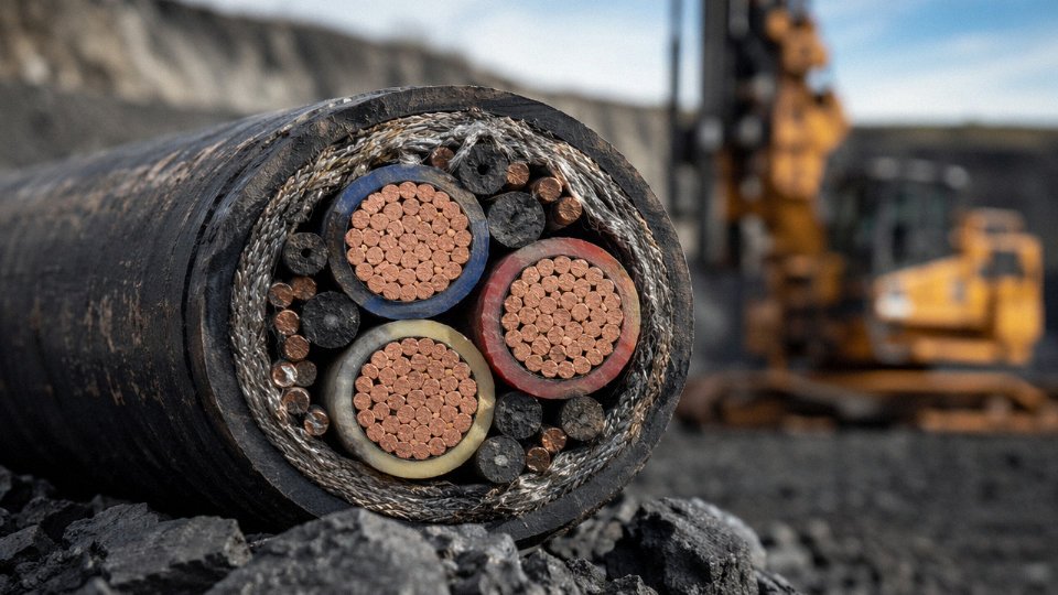
Mining trailing cables rated for methane-risk environments require both flame-retardant and anti-static jacket compounds under IEC and MSHA requirements.True
IEC 62086 and MSHA 30 CFR Part 18 both specify surface resistivity and flame propagation limits for cables used in potentially explosive mine atmospheres, specifically to prevent electrostatic discharge ignition and flame propagation along cable runs.
Welding Cables: Simple Construction, Demanding Duty
Welding cables are arguably the most mechanically abused cables in any plant. A 400 A welding lead gets dragged across a concrete floor, coiled, uncoiled, stepped on, and occasionally run over by a forklift. The construction is deliberately simple: Class 6 fine-wire copper conductor, natural rubber or neoprene jacket, voltage rating of 100 V (the open-circuit voltage of a welding set doesn’t justify heavier insulation), and current ratings roughly 200 A to 600 A depending on conductor cross-section and the duty cycle. IEC 60245-6 covers the detailed requirements. The jacket needs to be thick enough to resist abrasion without being so stiff it fights the welder’s hand movements — 2 mm to 3 mm is a typical wall thickness range, depending on cable size.
Crane Trailing Cables and Festoon Systems
Bridge cranes introduce a different stress pattern: the cable must feed power to a trolley or bridge that travels repeatedly across a fixed span, which means it’s looping and unlooping continuously. Flat cable designs handle this better than round cables because they bend preferentially in one plane and resist twisting. Some versions incorporate a steel messenger wire to carry the tensile load so the conductors themselves aren’t supporting the cable’s weight during the span. Torsion-resistant conductor lay geometry — achieved by reversing the lay direction between layers — prevents the cable from trying to rotate as it bends, which would otherwise corkscrew the assembly over time.
Festoon systems on automated production lines, particularly in automotive body shops and logistics warehouses, push the flex cycle requirement further still. PUR (polyurethane) jacketed cables are the standard here: lighter than rubber, oil-resistant enough for most factory environments, and rated by reputable manufacturers for 10 million flex cycles or more in a properly designed festoon track. The jacket needs to be compatible with whatever cable carriers and connector housings the machine builder specifies — this is one of those details that gets overlooked at procurement stage and causes integration headaches on the plant floor.
Jinda’s rubber cable range covers welding cables, TRS mining cables, and crane/festoon designs with rated voltages up to 6/10 kV for mining trailing applications. Available certifications include CE for European market access, IECEx for equipment used in explosive atmospheres, and MSHA approval for North American mining operations — which matters if you’re supplying cable into US underground coal mines, where MSHA approval is a non-negotiable procurement requirement, not an optional add-on.
Data, Communication, and Fiber Optic Cables: Cat 6A, Coaxial, and Fiber Compared
Structured cabling looks deceptively simple until you’re standing in a data center at 2 a.m. watching a 10GbE link drop packets because someone specified Cat 6 instead of Cat 6A for a 70-meter horizontal run. The performance gap between cable categories is real, measurable, and not recoverable without a repull.
Twisted-Pair Ethernet Categories: What the Numbers Actually Mean
Cat 5e handles 100 MHz bandwidth and sustains 1 Gbps to 100 m — still perfectly adequate for standard office workstations and IP phones. Cat 6 doubles that to 250 MHz and can run 10 Gbps, but only to roughly 55 m; beyond that, alien crosstalk degrades the signal enough that the link falls back. Cat 6A extends 10 Gbps reliably to the full 100 m channel length by pushing bandwidth to 500 MHz and — critically — requiring tighter construction tolerances to suppress alien crosstalk between adjacent cables in a high-density tray. Cat 8 operates at 2,000 MHz and supports 25/40 Gbps, but the 30 m reach limit essentially confines it to top-of-rack switch-to-server patch runs inside the cabinet. Each step up costs more per meter and, in Cat 6A and Cat 8, produces a noticeably thicker, stiffer cable that affects conduit fill calculations.
Shielding Notation: Decoding F/UTP, S/FTP, and Everything Between
The ISO/IEC notation lists the overall shield first, then the pair shield. UTP has neither. F/UTP wraps all four pairs in a single foil — good for moderate EMI environments. S/FTP adds a braided overall shield on top of individual foil-wrapped pairs, which is the standard for Cat 6A in dense server-room deployments where alien crosstalk between cables is the dominant failure mode. In practice, many installers underestimate how much a poorly grounded S/FTP shield can actually introduce noise rather than reject it if the drain wire isn’t terminated properly at both ends with a solid chassis ground. That’s not a cable quality issue; it’s an installation discipline issue.
Coaxial Cable: Impedance Matters Before Anything Else
RG-6 (75 Ω) is the default for CATV distribution and satellite IF runs — the impedance matches the distribution equipment. RG-58 (50 Ω) still shows up in RF instrumentation loops and legacy 10Base-2 segments, though the latter is rare now. For serious antenna work — base station feedlines, outside broadcast, remote sensing nodes — LMR-400 and LMR-600 (both 50 Ω) offer significantly lower attenuation per 100 m than RG-58, typically 4–6 dB/100 m at 1 GHz versus 20+ dB for RG-58. Mixing 50 Ω and 75 Ω components in a single run introduces impedance mismatch and return loss that no amount of signal amplification fixes cleanly.
Fiber Optic Types: Multimode vs. Single-Mode in Practical Terms
Multimode fiber comes in several grades. OM1 (62.5 µm core) was designed for LED sources and maxes out around 275 m at 1 Gbps — most installers have stopped specifying it for new builds. OM3 and OM4 (both 50 µm, optimized for 850 nm VCSEL sources) support 10 Gbps to 300 m and 400 m respectively. OM5 adds a wider usable wavelength range (850–953 nm) to support SWDM (shortwave wavelength division multiplexing), which stretches 40–100 Gbps over existing 50 µm fiber — useful when you want to upgrade bandwidth without replanting fiber.
Single-mode OS1/OS2 (9 µm core) is a different conversation entirely. OS2 is low-water-peak cable intended for outside plant; OS1 is tighter-spec indoor/outdoor. Distance limitations are essentially about optical budget and amplifier spacing, not the fiber itself — campus rings of several kilometers are routine. G.657 bend-insensitive variants tolerate tight bends around conduit corners and patch panel routing that would cause unacceptable insertion loss in standard G.652 fiber.
Single-mode fiber has no practical distance limit for data transmissionFalse
Single-mode fiber has very low attenuation (~0.2 dB/km for OS2), but signal loss still accumulates. Long-haul runs require optical amplifiers or regenerators; the 'unlimited distance' claim applies only in comparison to copper, not in absolute engineering terms.
Industrial Ethernet and Hybrid Cables
Office-grade Cat 6A patch cords fail within months on a factory floor. Industrial Ethernet cables — PROFINET Type A (shielded, fixed install), Type B (shielded, flexible), and Type C (drag-chain rated) per IEC 61784 — are built with oil-resistant TPE or PUR jackets, rated to 60–100°C depending on construction, and tested for mechanical flex cycles in the millions for moving installations. The shielding on these cables is also heavier gauge and bonded differently than data center variants to handle the conducted EMI environment near VFDs and servo drives.
Hybrid copper-fiber composite cables — a single jacket containing both fiber and copper conductors — are increasingly specified for IP camera runs, small cell 5G antenna installations, and remote I/O nodes where one conduit pull must carry both data and 48 V DC or PoE power. The trade-off is that you’re now dealing with two termination disciplines in one cable, and field splicing requires someone competent in both.
Specialty and High-Performance Cables: Fire-Resistant, LSZH, Submarine, and High-Temperature Types
Standard commercial cables are designed for normal service conditions. These categories are not. Each one exists because a standard cable failed — or would fail — in a specific environment, and the consequences of that failure range from expensive to fatal.
Fire-Resistant Cables (FRC): Keeping Circuits Alive During a Fire
The distinction engineers most often get wrong is between flame-retardant and fire-resistant. A flame-retardant cable resists ignition and slows flame spread. A fire-resistant cable keeps the circuit electrically functional while it is actively burning. That difference matters enormously for emergency lighting, smoke exhaust fan circuits, and fire alarm wiring — circuits that must stay live precisely when everything around them is on fire.
Construction is the key: FRC typically wraps the conductor in mica tape before the primary insulation goes on. Mica stays structurally intact above 1,000°C. IEC 60331 classifies performance in 30, 60, 90, and 120-minute ratings, tested at roughly 750–950°C depending on the variant. Specifying the right survival duration requires knowing your building’s evacuation time assumptions — a common gap in specs written by architects rather than electrical engineers.
LSZH / LSHF: Why the Jacket Compound Matters in Confined Spaces
In a tunnel, a metro car, or an offshore platform, the insulation compound on a burning cable can kill people faster than the fire itself. PVC insulation releases hydrogen chloride gas (HCl) — corrosive, toxic, and it drops visibility to near zero in enclosed spaces. Low-smoke zero-halogen (LSZH, also written LSHF) formulations eliminate halogenated compounds from both insulation and jacket.
Certification requires passing IEC 60754 (acid gas emission) and IEC 61034 (smoke density). The oxygen index must typically exceed 30% — meaning the material needs an atmosphere of more than 30% oxygen to sustain combustion, versus roughly 21% in air. Don’t accept a supplier’s verbal claim on this. Ask for test certificates referencing the specific cable construction, not a generic compound datasheet.
High-Temperature Cables: PTFE and Silicone Rubber
PTFE (polytetrafluoroethylene) insulation handles continuous service to 260°C — the only realistic insulation choice for industrial oven wiring, aerospace harnesses, and certain downhole oil and gas instrumentation. It’s expensive, and terminating it properly requires attention to its cold-flow tendency under compression fittings. Silicone rubber cables, typically rated 180–200°C continuous, cover furnace perimeter wiring and engine bay installations where PTFE’s cost isn’t justified. Silicone tears more easily during installation, which is usually the failure mode people don’t anticipate.
Submarine and Subsea Cables
These need genuine mechanical and moisture barriers, not just a heavy jacket. A typical medium-voltage submarine cable runs: conductor → XLPE insulation → semi-conductive screens → lead sheath or corrugated aluminum sheath as the water barrier → HDPE outer jacket → double steel wire armor for protection against anchor strikes and bottom trawling. Jinda supplies medium-voltage submarine cables for island grid interconnection projects, where the combination of corrosion resistance and mechanical survivability over the cable’s 25–30 year design life is non-negotiable.
Solar PV Cables and Wind Energy Cables
Standard building wire fails in open-air PV string installations within a few years — UV degradation, ozone cracking, and temperature cycling from −40°C to +90°C destroy conventional PVC before the panels reach half their design life. PV cables must meet TÜV 2 Pfg 1169 or EN 50618 (H1Z2Z2-K). It’s a surprisingly common procurement error on smaller rooftop projects.
Wind turbine nacelle-to-tower power runs are a different problem: continuous torsional movement as the nacelle yaws. This demands IEC 60228 Class 6 fine-wire conductors, EPR insulation for flexibility at low temperatures, and SHF2 jacket compound rated for offshore salt spray. Standard Class 2 conductors will work-harden and fracture within months under that twisting cycle.
Rail Transit: HFFR-A Cables and EN 45545-2
Rolling stock and trackside wiring must meet EN 45545-2 hazard level requirements — HL1 through HL3 depending on tunnel length and evacuation difficulty. Halogen-free, flame-retardant, armored (HFFR-A) construction combines the smoke/toxicity performance of LSZH with mechanical protection against the cable management realities of rail environments: vibration, rodent exposure in trackside troughs, and maintenance staff who occasionally stand on cable bundles. Jinda has supplied cable packages for metro infrastructure projects, and the specification review process on these jobs typically uncovers at least a few positions where standard industrial cable had been mistakenly quoted.
Mica tape in fire-resistant cables maintains circuit integrity under direct flame because mica remains structurally stable above 1,000°C, unlike PVC or XLPE insulation which degrade rapidly above 200–300°C.True
This is the established physical basis for FRC construction per IEC 60331 test methodology. Mica's thermal stability is well-documented in materials science and is the reason it is specified as the primary fire-survival barrier layer in these cables.
How to Select the Right Cable Type: A Step-by-Step Technical Specification Framework
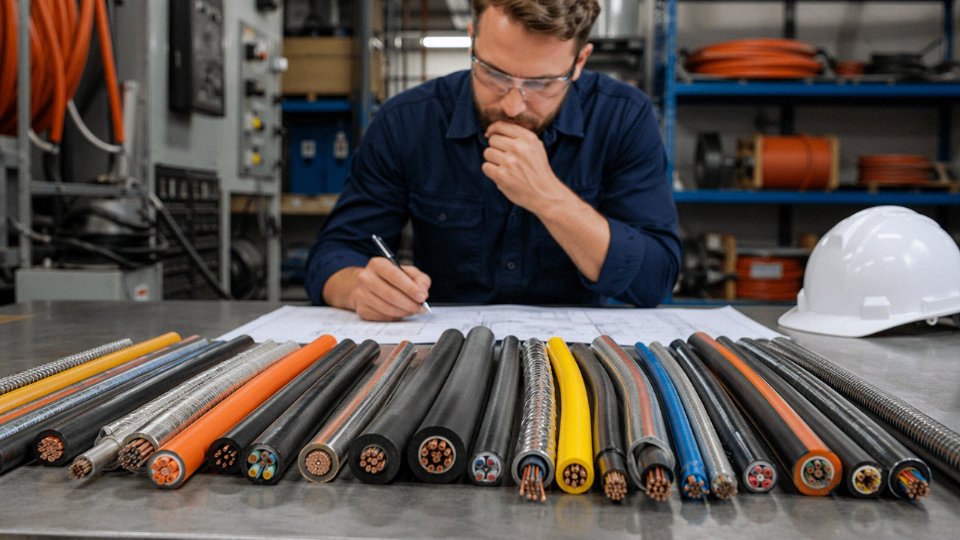
Getting the cable type wrong isn’t just a purchasing mistake — it’s a future maintenance event, or worse, a fire. The sections above have covered a wide range of cable families. This framework pulls those threads together into a repeatable specification process you can apply whether you’re wiring a conveyor drive panel or sourcing MV feeder cable for a substation extension.
Step 1 — Define the Electrical Parameters First
Before anything else, establish the system voltage expressed as U₀/U (phase-to-earth / phase-to-phase), the maximum continuous load current, the prospective short-circuit current and its clearance time, and the power factor if reactive loading is significant. These four numbers together constrain nearly every downstream decision.
Under IEC 60364 or NEC Article 310 load calculation methods, the continuous current determines minimum conductor cross-section before any derating. The short-circuit current and duration determine whether the conductor can survive a fault thermally — a 70 mm² copper conductor that handles 200 A continuous may be undersized if your upstream protection clears faults in 1.0 s rather than 0.1 s. Don’t skip this check; it’s the one most often omitted on smaller industrial projects and the one most likely to cause a nuisance burnout.
Step 2 — Characterize the Installation Environment in Detail
Ambient temperature, soil thermal resistivity (for direct buried runs — typically 0.7 to 2.5 K·m/W depending on soil moisture content and type), presence of water, oil, chemicals, UV exposure, mechanical impact risk, and whether the location falls within an ATEX or IECEx classified zone: each of these maps to a specific jacket compound, armor style, or certification requirement.
A cable routed through a chemical dosing area needs something other than standard PVC — perhaps a chlorinated polyethylene or LSZH compound with demonstrated resistance to the specific reagent involved. An outdoor roof-mounted tray run in a high-UV environment in the Middle East will degrade a standard PVC jacket noticeably faster than the same cable in a temperate climate. These aren’t hypothetical risks; they show up as cracked outer sheaths within five to seven years rather than the expected twenty-plus.
Step 3 — Identify the Governing Standards and Required Certifications
Determine early which standard regime applies: IEC, NEC/UL, BS, VDE, GB, or some combination on multinational projects. A cable manufactured to IEC 60502-1 is not automatically compliant with a US project requiring UL listing, even if the electrical ratings appear equivalent.
Mandatory third-party certifications vary by sector. Offshore and marine work typically requires DNV or Lloyd’s Register type approval. Mining applications in the US require MSHA acceptance. Life-safety systems in many jurisdictions require LSZH cables with fire performance tested to IEC 60332 or EN 50575 reaction-to-fire classes. Get this list confirmed with the end client or authority having jurisdiction before issuing a purchase order, not after the cable arrives on site.
A cable manufactured to IEC 60502-1 meets equivalent UL 1072 performance requirements and can substitute for a UL-listed cable on US projects.False
IEC 60502-1 and UL 1072 have differing test methods, insulation thickness requirements, and qualification processes. Regulatory acceptance in the US requires actual UL listing or approval by the authority having jurisdiction — an IEC mark alone does not satisfy this.
Step 4 — Calculate Conductor Cross-Section and Verify Voltage Drop
Apply IEC 60364-5-52 current-carrying capacity tables (or NEC Table 310.16 equivalents) as your starting point, then stack the derating factors: ambient temperature correction, grouping factor for cables installed in bunches, and installation method (buried, tray, conduit, free air). In practice, a 6-cable group in a fully loaded tray at 45 °C ambient can reduce the tabulated current capacity by 40–50% compared to a single cable in free air at 30 °C. That’s not a marginal effect — it regularly pushes the required cross-section up by two or three standard sizes.
After sizing for current, verify voltage drop along the full circuit length. IEC and most European standards accept 3–5% drop at full load for final circuits; some sensitive process equipment requires tighter limits, sometimes 1–2%. On long runs — say, a 400 m feeder to a remote pump station — voltage drop often governs the conductor size rather than current capacity, and this is where switching from copper to aluminum starts to complicate the economics because the larger aluminum cross-section needed to match copper’s resistivity (aluminum runs about 64% higher resistivity than copper at the same cross-section) partially offsets the material cost advantage.
Step 5 — Specify the Mechanical Protection Level
Select between unarmored, steel wire armored (SWA), steel tape armored (STA), installation in conduit, or open cable tray based on the physical hazards at each point along the route. Buried cables crossing a vehicle access road need heavier armor and usually a concrete tile warning layer above them. Cables installed in a cable tray above a production floor need no armor but may need a physical guard where they pass through maintenance walkways.
Don’t overlook pulling tension during installation. Long conduit runs with multiple bends impose tension and sidewall pressure loads that can deform or crack the insulation before the cable ever carries current. Calculate pulling tension against the manufacturer’s stated limit — typically expressed in N or kgf — and plan intermediate pulling points accordingly.
Step 6 — Evaluate Total Cost of Ownership, Not Just Purchase Price
Copper currently trades in the USD 8,000–9,500 per tonne range (subject to LME volatility — check live pricing before any major buy decision). For large-volume projects, that spread matters. XLPE insulation carries a slightly higher initial cost than PVC but offers a realistic service life of 30 years or more versus roughly 20 years for standard PVC in normal operating conditions, with better thermal rating and lower dielectric losses at higher voltages. Over a 25-year project life, the cost of one cable replacement in an inaccessible underground duct — including excavation, traffic management, and production downtime — typically dwarfs the original insulation upgrade cost several times over.
Procurement Checklist: Eight Data Fields Every Cable Purchase Order Must Contain
| Field | Example Entry |
|---|---|
| Product standard | IEC 60502-1, 2019 edition |
| Rated voltage | 0.6/1 kV |
| Conductor material and IEC class | Copper, Class 2 stranded |
| Insulation type | XLPE |
| Jacket / armor type | PVC outer sheath, SWA |
| Conductor cross-section | 95 mm² |
| Number of cores | 3 cores + 1 earth |
| Required certifications | CE, BASEC or equivalent third-party test report |
Leaving any of these fields vague invites a supplier to substitute a compliant-but-different product — different armor wire gauge, different insulation compound, different conductor class — and you may not catch it until a site inspector flags it or, in the worst case, until something fails. A complete, unambiguous purchase order is the single cheapest quality-assurance step in the entire cable procurement process.
Frequently Asked Questions About Cable Wire Types
What is the difference between a cable and a wire?
A wire is a single conductor — either solid or stranded — with or without insulation. A cable is an assembly of two or more individually insulated conductors laid up together under a common outer sheath or jacket. That’s the formal distinction under IEC 60050.
In practice, the terms get used interchangeably on the trade floor all the time. Electricians will say “wire” when they mean a multi-core PVC-jacketed cable, and procurement documents sometimes list “hook-up wire” for what is technically a single-conductor insulated product. The blurring causes real specification errors on international tenders, particularly when translating between regional standards, so it’s worth being precise in purchase specs even if the shop floor isn’t.
What is the most commonly used cable type in industrial facilities?
By installation volume, XLPE-insulated, PVC-jacketed, steel wire armored power cable — typically IEC 60502-1 compliant, rated 0.6/1 kV — handles the bulk of power distribution inside plants. Pair that with PVC or LSZH insulated multi-core control cable running to switchgear, MCC panels, and PLC I/O racks, and those two product families cover somewhere between 70–80% of the cable meters laid in a typical greenfield industrial facility, depending on process complexity.
High-automation plants (automotive, semiconductor) skew toward more instrumentation pairs and shielded control cable. Heavy extractive industries add more armored medium-voltage cable. But for most general manufacturing or process plants, those two types are the workhorses.
Can I use PVC cable outdoors in direct sunlight?
Standard PVC jacket compounds are not formulated for prolonged UV exposure. In high-UV climates — Middle East, equatorial regions, high-altitude sites — a standard black PVC jacket can start chalking and cracking within five to ten years, sometimes faster if the installation also sees thermal cycling from day/night temperature swings. Once the jacket is brittle, mechanical protection is gone and moisture ingress follows.
For exposed outdoor runs, specify UV-stabilized PVC, HDPE, or cross-linked polyolefin (XLPO) jackets. For solar PV string and DC trunk cable specifically, H1Z2Z2-K is the purpose-designed type and it’s worth the modest premium to avoid replacing arrays in year eight.
What does LSZH cable mean and when is it required?
LSZH stands for low-smoke zero-halogen (also written LSHF or OHLS depending on the standard you’re reading). The insulation and jacket compounds contain no chlorine, fluorine, or bromine. When the cable burns, it produces very little smoke and no hydrogen chloride gas — which matters enormously in confined spaces where evacuating people and protecting nearby electronics both depend on visibility and air quality.
Mandatory applications typically include metro tunnels, railway rolling stock, airports, hospitals, offshore platforms, and public assembly buildings. Some industrial clients now specify it site-wide for data centers or clean rooms. It costs more than standard PVC cable — roughly 15–35% more depending on conductor cross-section and core count — and the jacket is generally less mechanically tough, so it’s not a universal substitute.
LSZH cables produce minimal smoke and no hydrogen chloride gas when burned, improving evacuation safety in confined spaces.True
LSZH compounds are halogen-free by formulation; combustion testing per IEC 60754-1 and IEC 61034-2 verifies low halogen acid gas emission and smoke density, which is the basis for the mandatory specification in tunnels, metro systems, and public buildings.
How do I know which voltage rating my cable needs?
Cable rated voltage is expressed as U₀/U — phase-to-earth voltage over phase-to-phase voltage. For a standard 400 V three-phase distribution system, a 0.6/1 kV cable is the correct selection: U₀ of 600 V covers the phase-to-earth stress, U of 1,000 V covers phase-to-phase. Never select a cable whose rating exactly matches the operating voltage with no margin. Transient overvoltages, switching surges, and earth fault conditions during the fault clearance period all stress the insulation beyond nominal operating levels.
For medium-voltage feeders at 6 kV, 10 kV, or 33 kV, the voltage class must be confirmed against both the nominal system voltage and the earthing arrangement — unearthed or impedance-earthed systems require a higher U₀ class than solidly earthed systems of the same nominal voltage.
What is the expected service life of a properly installed underground power cable?
Realistically, XLPE-insulated medium-voltage cables installed per IEC guidelines in well-prepared trench conditions — proper bedding sand, adequate depth, route markers, no sharp backfill material — are designed for 30 to 40 years. PVC-insulated LV cables in stable soils, without excessive thermal loading, typically reach 25 to 35 years.
Those numbers assume the cable was installed correctly. In practice, premature failures trace back to a handful of causes: water ingress through a nick in the sheath made during installation, sustained thermal overload from a circuit that got up-rated without re-checking ampacity, and mechanical damage from later excavation work that hit an unmarked route. The cable design accounts for the first 30 years; the installation and route documentation determine whether you actually get them.
Does Jinda Cable supply cables meeting both IEC and North American UL/NEC standards?
Yes. Jinda manufactures cables conforming to IEC, GB, VDE, BS, and selected UL/CSA standards to support multinational project requirements. Export products are supplied with test reports and third-party certifications matched to the destination country’s requirements. For projects that need dual-certification or where the applicable standard isn’t immediately obvious — which happens regularly on projects in emerging markets that blend European equipment with North American code compliance — Jinda’s technical sales team can review the project specification and recommend the appropriate product and documentation package.
Why Jinda Cable Is a Trusted Global Supply Partner for All Cable Wire Types
Choosing the right cable type is only half the problem. The other half is finding a manufacturer who can actually deliver it — on spec, on time, with paperwork that clears customs without a fight. That second half is where a lot of infrastructure projects quietly bleed money and schedule.
Manufacturing Depth That Eliminates Subcontracting Risk
Jinda operates five production bases across China, totaling 470,000 m² of factory floor. To put that in perspective: a mid-sized cable factory might run 30,000–50,000 m² and specialize in two or three product families. Five bases at that combined scale means Jinda runs power cable extrusion lines, rubber compounding and vulcanization equipment, multi-core stranding machines for control and instrumentation cables, and LSZH compound processing — simultaneously, without farming work out to third parties.
For a large infrastructure contractor managing, say, a substation build alongside a process plant expansion, that matters enormously. Subcontracted production introduces a second quality gate you can’t audit, a second lead time you can’t control, and a second point of failure when volumes spike. Vertical integration — wire drawing through finished cable testing under one management system — is a genuine supply-chain risk reduction, not a marketing claim.
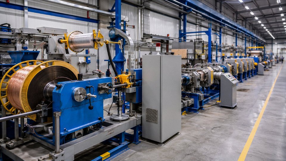
Jinda Cable operates five production bases in China with a combined manufacturing area of 470,000 m², covering power, control, rubber, LSZH, PV, and data cable production lines.True
Stated manufacturing footprint consistent with a vertically integrated multi-product cable group established in 1987 with documented export history across 50+ countries.
One Supplier Across the Full Cable Spectrum
The catalog spans from 1.5 mm² building wire up through 35 kV medium-voltage power cables, alongside control and instrumentation cables, EPR/EPDM rubber mining and welding cables, LSZH fire-resistant cables, PV DC cables rated for photovoltaic string wiring, and structured data cables. That breadth matters operationally. A project contractor who can consolidate even four or five cable families into a single supplier relationship reduces purchase orders, reduces inspection trips, and usually gets better pricing on the combined volume than splitting the work across specialists.
Quality Credentials Built for Export Documentation
Products are manufactured and tested against IEC 60502, IEC 60228, IEC 60332, IEC 61034, and GB/T 12706, with ISO 9001 quality management system certification covering the full production process. Third-party laboratory test reports are available for export documentation — relevant for projects in markets where customs authorities or project owners require independent verification rather than self-declared compliance. In practice, having those reports ready before order placement shortens pre-qualification by weeks, sometimes more.
Thirty-Seven Years of Export Experience
Jinda has been supplying international customers since 1987, with active shipments to buyers across Southeast Asia, the Middle East, Africa, Europe, and South America. The in-house documentation team handles letters of credit, certificates of origin, and customs compliance paperwork for major importing markets — the kind of institutional knowledge that only accumulates through years of actual transactions, not through a compliance checklist.
Technical Support That Shortens the Qualification Cycle
Jinda’s engineering team provides cable sizing assistance and standard equivalency guidance — mapping an IEC specification to the nearest GB equivalent, or advising on whether a customer’s UL-referenced spec has a practical IEC counterpart. Sample submission for pre-approval testing is available for new project partnerships. For procurement teams qualifying a new supplier, that shortens the cycle considerably.
How to Start a Conversation
Project engineers and procurement managers are encouraged to submit technical specifications or quantity inquiries directly to Jinda’s international sales team. The response typically includes a rapid quotation, relevant product data sheets, test report availability, and complimentary engineering consultation on sizing or standard equivalency. No obligation, and the engineering input alone usually pays for the email.