Specifying the wrong armored cable for a direct-burial run or a wet industrial trench is one of those mistakes that rarely announces itself immediately — it shows up six months later as insulation breakdown, ground faults, or a corroded armor layer that offers no mechanical protection whatsoever by the time anyone notices. Replacing a buried cable run means excavation costs, production downtime, and in some plants a full shutdown window that has to be negotiated weeks in advance. Getting the armor type right at the procurement stage costs nothing extra; getting it wrong can run well into five figures before the job is done.
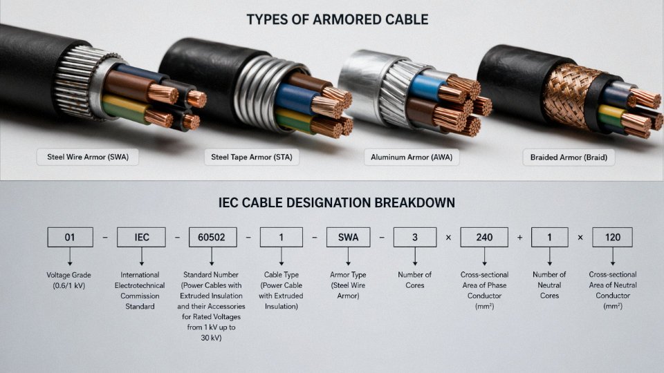
Armored cables fall into several main types based on their armor construction: Steel Wire Armored (SWA), Steel Tape Armored (STA), Double Steel Tape Armored (DSTA), Aluminum Wire Armored (AWA), and Aluminum Tape Armored (ATA). The right choice depends on installation method, soil conditions, voltage rating, mechanical load, and whether weight or corrosion resistance is a priority — no single type suits every application.
What makes this more complicated in practice is that the naming conventions overlap, regional standards differ (BS 5467, IEC 60502, and various national derivatives all handle armor classification slightly differently), and suppliers don’t always volunteer the distinction unless you ask specifically. The sections below break down each armor type by construction, mechanical behavior, and where it actually makes sense to use one over another.
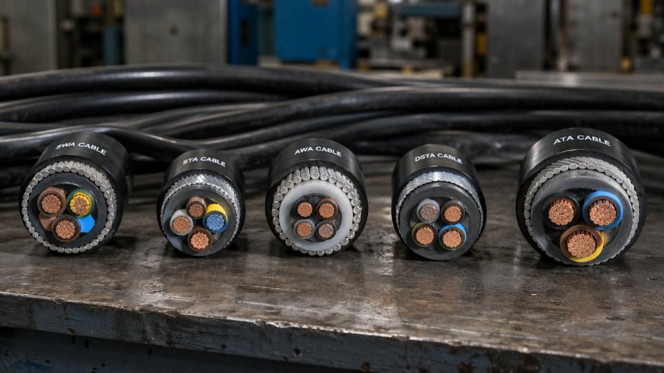
Steel Wire Armored (SWA) Cable: Construction, Ratings, and Typical Use Cases
SWA is the workhorse of industrial and utility cabling worldwide — and for good reason. The construction is straightforward enough to manufacture reliably at scale, yet the mechanical performance it delivers is hard to match with any lighter alternative.
How SWA Is Built
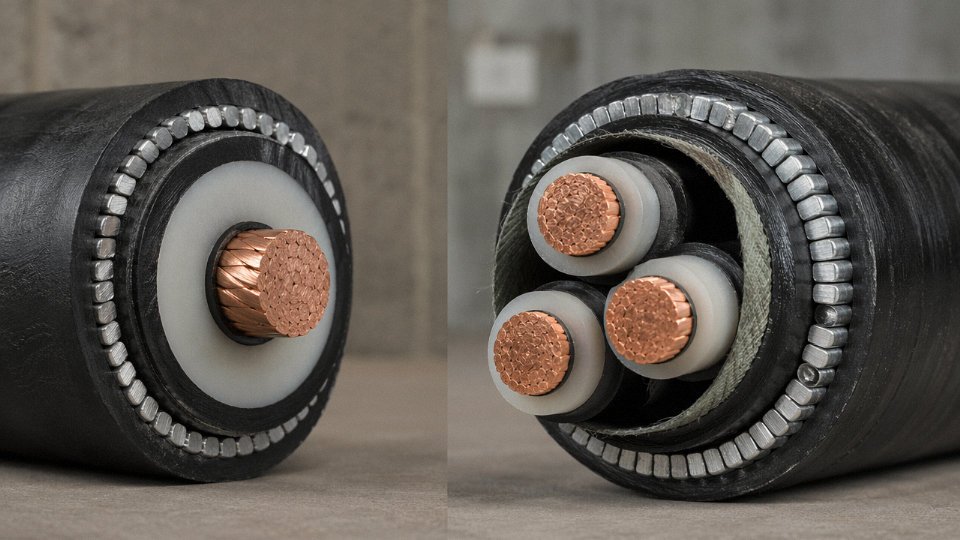
The armor layer consists of individual galvanized steel wires laid helically over an extruded inner sheath, which itself sits over the insulated conductors. That helical lay is not an arbitrary detail. A shorter lay length increases flexibility and makes the cable easier to pull around bends, but it slightly reduces axial tensile strength. A longer lay favors tensile performance — useful for vertical drops into mine shafts or deep riser installations — at the cost of some bend radius tolerance. Most specifiers never ask about lay length, and most of the time that’s fine, but on a 60-meter vertical riser inside a wind turbine tower it absolutely matters.
Wire diameter scales with overall cable size. For small cables — say, a 4-core 2.5 mm² — the armor wires are typically around 0.9–1.25 mm in diameter. As you move up to large multicore cables in the 185–400 mm² range, wire diameters climb to 2.5–3.15 mm. The selection isn’t arbitrary; it’s driven by the need to keep the armor’s cross-sectional area proportional to the short-circuit earth-fault current the cable may need to carry back through the armor in a fault condition.
Voltage Classes in Practice
Low-voltage SWA rated 0.6/1 kV covers the vast majority of building distribution, cable tray runs in factories, and sub-main feeders to distribution boards. It’s the spec you see on almost every industrial greenfield project because it’s cost-effective, termination hardware is universally available, and electricians are familiar with it.
Medium-voltage SWA — covering 3.6/6 kV through 18/30 kV — serves utility distribution networks, large industrial feeders (think a 10 kV feed to a compressor station or a substation), and increasingly, the array and feeder cables in onshore wind and solar farms. At these voltages the cable incorporates conductor screening and insulation screening layers in addition to the armor, and the overall design is governed by standards like IEC 60502-2.
At 33 kV, SWA is available and specified in some markets, particularly in the UK where BS 6622 / BS 7835 have a long track record. Above roughly 15 kV, though, wire-screened or corrugated aluminum-sheath designs become competitive because the dielectric performance requirements start to dominate the design more than the mechanical ones.
Tensile Strength: Where SWA Earns Its Specification
SWA cables can handle longitudinal pulling loads in the range of roughly 5 kN for small LV cables up to 50 kN or more for large MV multicore types — the actual figure depends on conductor cross-section, number of cores, and armor wire diameter. That pulling capacity is what makes SWA suitable for direct-buried long runs, horizontal duct pulls through congested routes where the cable has to travel 100 meters or more without intermediate access, and vertical installations where the cable’s own weight generates sustained tensile stress. An unarmored cable in those same scenarios either requires external support systems that add cost and complexity, or it simply isn’t acceptable under the relevant installation standard.
Bonding the Armor: A Step Many Sites Get Wrong
For multicore SWA, standard practice is to bond and earth the armor at both ends. This completes the earth-fault return path and keeps touch voltages on the armor sheath at safe levels. Single-core SWA is a different situation — bonding at both ends creates a closed loop that, in an AC system, will drive circulating currents through the armor proportional to the load current. On a heavily loaded single-core 240 mm² feeder, those circulating currents can reach values that cause measurable heating and real energy loss. Single-point bonding, or in some designs solid bonding with cross-bonding at intermediate points on longer runs, is the correct approach. It’s documented in IEC 60364 and most national wiring codes, but in practice I’ve seen site electricians bond both ends of single-core SWA simply because that’s what they always do with multicore — and nobody questions it until the cable joint gets warm.
Single-core SWA cables should use single-point armor bonding in AC power installations to prevent circulating currents.True
Bonding armor at both ends of a single-core AC cable forms a closed magnetic circuit, inducing circulating currents that cause resistive heating and energy loss. IEC 60364-5-54 and engineering guidance such as ERA 69-30 address this; single-point or cross-bonding schemes are the accepted engineering solution.
Primary Application Environments
SWA dominates in utility underground distribution where mechanical protection during backfill and future ground disturbance is non-negotiable. Industrial plant feeders running through cable trenches alongside pipe racks benefit from the crush resistance. Renewable energy projects — particularly onshore wind farms where array cables run through agricultural land with periodic heavy vehicle traffic overhead — specify SWA almost universally because the alternatives require conduit systems that add installation cost. Commercial building sub-mains, especially in basement plant rooms and risers, use SWA because it doubles as the circuit protective conductor without a separate earth cable.
Direct burial in agricultural or infrastructure ground is another consistent use case, though burial depth requirements (typically 0.6–1.0 m for LV, deeper for MV depending on the jurisdiction and soil classification) and the need for marker tape above the cable are separate site decisions that don’t change the cable specification itself.
SWA vs. Unarmored Cable: Quick Comparison
| Characteristic | SWA Cable | Unarmored Cable |
|---|---|---|
| Direct burial suitability | Yes, with appropriate depth | No — requires conduit or duct |
| Tensile load capacity | 5–50 kN (depends on size) | Low — jacket only, no structural layer |
| Short-circuit armor earth return | Yes — armor carries fault current | No separate armor path |
| Rodent resistance | High — steel deters gnawing | Low to moderate |
| Bend radius | Larger (typically 8–12× OD) | Smaller (6–8× OD typical) |
| Installed cost index | 1.3–1.8× equivalent unarmored | Baseline |
The cost premium of SWA over unarmored cable — roughly 30–80% more depending on conductor size, voltage class, and steel prices at time of procurement — needs to be weighed against the cost of the conduit, duct, or mechanical protection system the unarmored alternative would require. On most direct-burial or heavy-industrial projects, SWA is cheaper overall once installation is factored in.
Steel Tape Armored (STA) Cable: Where Crush Resistance Matters More Than Tensile Strength
STA cable gets specified less often than SWA in global project databases, but in the right environment it outperforms wire armor decisively. Understanding why requires thinking about the actual threat geometry — radial crushing versus longitudinal tension — rather than defaulting to whichever armor type appeared on the last project.
How STA Is Built and Why Two Tapes
The armor consists of two cold-rolled steel tapes wound helically over the cable core, each tape typically 0.2–0.5 mm thick (thicker end of that range for cables above roughly 50 mm overall diameter). They’re applied in opposite helical directions, each with a minimum 15% overlap, so that no gap in one tape aligns with a gap in the other. That opposing-wind, overlapping geometry is the point: a single tape, wound in one direction, would leave a continuous helical gap under mechanical load. Soil settlement, conduit movement, or point-load pressure from cable tray hardware would find that gap immediately. Two tapes in opposing directions close off that path.
The steel grade is typically low-carbon cold-rolled strip — similar spec to what you’d see in light-gauge roofing profiles — with a galvanized or bitumen-coated finish to slow corrosion in damp environments. Tape thickness is more tightly toleranced than wire diameter in SWA, because tape overlap geometry depends on it.
The Crush Resistance Advantage — and Its Real Limits
STA cables in the 16–150 mm² range typically withstand radial crush loads of roughly 3,000–5,000 N per 10 cm of cable length, depending on tape thickness, core diameter, and how well the bedding layer beneath the tape is supporting the load. That’s meaningfully higher than SWA for the same nominal cable diameter, because the tape distributes point loads across a larger contact area rather than concentrating them at wire contact points.
This matters enormously in congested cable trays where cables are stacked three or four deep with tray cover fasteners pressing down, or in factory floor conduit runs where a forklift could roll over a surface-mounted section. Petrochemical instrument cable routes are a classic STA environment — the cable may cross under pipe supports, run through cable transits with tight sidewall pressure, and never experience more than a short horizontal pull.
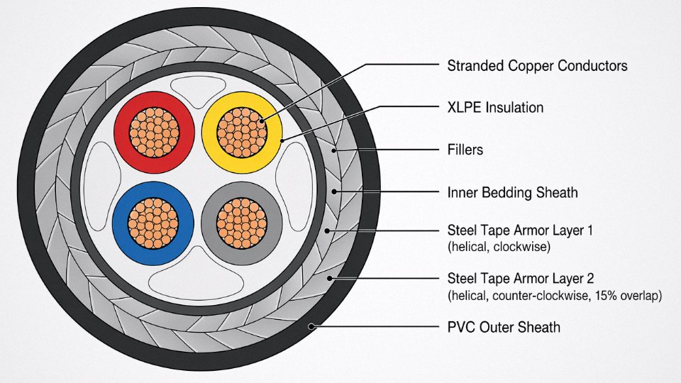
What STA cannot do is resist tensile load. The tape geometry provides almost no longitudinal strength — the tapes are not bonded to each other or to the core, and under axial tension they simply unwind slightly and the load passes directly to the conductors and insulation. An SWA cable with 2.5 mm galvanized steel wires across a 70 mm² multicore can sustain a tensile load in the range of 8–15 kN depending on wire count and lay; an equivalent STA cable might handle 1–2 kN before the armor contributes nothing useful. For any vertical drop longer than roughly 5–6 m, or for a direct-burial pull through dense or rocky soil over distances above 30–40 m, STA is the wrong choice without a separate support system (messenger wire, cleated support at intervals, or a dedicated pulling grip on the conductor assembly).
Standard Specification: XLPE/STA/PVC to IEC 60502-1
The workhorse specification for low-voltage industrial STA cable is XLPE-insulated, steel-tape armored, PVC-oversheathed — written as XLPE/STA/PVC and governed primarily by IEC 60502-1 for cables up to 1 kV. XLPE insulation gives a maximum continuous conductor temperature of 90°C and a short-circuit rating typically up to 250°C for the durations involved. Installation minimum is generally −20°C; below that, the PVC oversheath and tape bedding compound become brittle enough that bending risks cracking. In practice, cold-climate sites in northern Europe or high-altitude installations sometimes specify a low-temperature-rated sheath compound specifically, which shifts that limit to −40°C — worth catching at the procurement stage before cable arrives on site in January.
STA cables using two opposing helical steel tapes with minimum 15% overlap provide continuous circumferential armor coverage, preventing gap exposure under radial mechanical loads.True
The opposing wind directions ensure that the gap in one tape is covered by the solid section of the second tape, a well-established principle in IEC and BS armor construction standards.
Choosing Between STA and SWA: Three Questions
Before finalizing the specification, three questions narrow it down quickly.
| Question | STA | SWA |
|---|---|---|
| Is the dominant threat radial crush or point load? | Yes — specify STA | No — evaluate SWA |
| Does the route include vertical drops >5 m or long underground pulls? | No — STA acceptable | Yes — SWA required |
| Do tight bends exist where tape edges could stress the oversheath? | Flag for review — reduce bend radius or consider wire armor | No constraint |
That third question catches an installation failure mode that rarely appears in datasheets. On tight bends — say, a 90° elbow at less than 8× cable diameter — the outer tape edge can dig into the oversheath as the cable flexes during pull-in, creating a stress riser that doesn’t fail immediately but degrades the sheath over years of thermal cycling. SWA handles bends more forgivingly because individual wires articulate. If the route has multiple bends and the engineer is already on the edge of the minimum bend radius, SWA is usually the safer call regardless of what the crush load analysis says.
Aluminum Wire Armored (AWA) and Aluminum Tape Armored (ATA) Cable: Weight Reduction Without Sacrificing Protection
Aluminum armor follows the same geometric logic as its steel counterparts — helically applied wires for AWA, overlapping tape layers for ATA — but the material choice drives a fundamentally different performance profile. That difference isn’t cosmetic. In the right application, aluminum armor is the correct engineering answer; in the wrong one, it introduces failure modes that don’t show up until the cable has been in service for a year or two.
Alloy Grades and Why Annealed Aluminum Matters
Most AWA cables use either 1350-series (commercially pure, roughly 99.5% aluminum) or 6201 alloy wires. The 1350 grade dominates general-purpose AWA because its conductivity is high and it’s easy to draw into consistent wire diameters. 6201 shows up in applications where slightly higher tensile strength is needed — some subsea umbilical designs, for instance — though the strength gain is modest. What matters more in practice is temper: armor wires are supplied in the annealed (soft) condition specifically to preserve flexibility during installation. Full-hard aluminum wire would crack at the interlayer bends on a cable drum or during pulling around conduit bends. Annealing brings elongation up to roughly 15–25%, which keeps the armor intact through normal handling without sacrificing the radial crush resistance the armor is there to provide.
Weight Savings That Actually Change Structural Calculations
AWA cables run 30–40% lighter than equivalent SWA cables, give or take, depending on conductor cross-section and core count. On a 95 mm² 3-core cable, that translates to a meaningful reduction in meters-per-tray loading — the kind of number that matters when a structural engineer is signing off on tray support spacing on an offshore topside or a high-rise mechanical floor.
Shipboard installations and aerial self-supporting routes feel this even more sharply. A vessel electrical engineer dealing with a long cable run through multiple decks is not indifferent to weight; every kilogram adds up in a stability calculation. Same logic applies to cable ladders in tall buildings where the dead load from dozens of heavy runs can push structural steel requirements up a bracket size.
Corrosion Resistance — and the Bimetallic Trap
Aluminum armor genuinely outperforms galvanized steel in chloride-rich environments. Marine topsides, coastal substations, chemical plants with chlorinated process areas — in all of these, galvanized steel armor will eventually pit and lose mechanical integrity, especially once the zinc layer is breached. Aluminum forms a stable oxide layer that resists chloride attack well.
The problem is bimetallic corrosion. Aluminum armor sitting in direct contact with a steel cable tray, or terminated into a standard steel gland, sets up a galvanic couple that will eat the aluminum preferentially, particularly in the presence of moisture. The fix is straightforward but frequently skipped on busy installations: use brass, stainless steel, or aluminum-bodied glands rated for aluminum armor, and where the cable rests on steel trays in wet or coastal environments, use PVC-sleeved tray liners or nylon cable cleats to break the metal-to-metal contact.
Aluminum armor on single-core AC cables eliminates the eddy current heating problem that makes steel wire armor unsuitable for single-core conductors above approximately 16 mm².True
Steel is ferromagnetic. A single-core AC cable produces an alternating magnetic field; steel armor wrapped around it forms a shorted turn that sustains eddy currents, generating resistive heat that reduces ampacity and, in severe cases, accelerates insulation degradation. Aluminum is non-magnetic, so the eddy current loop does not form. This is why IEC and most national standards effectively mandate non-magnetic armor — AWA being the standard solution — on single-core AC power cables above this size threshold.
This is probably the most under-appreciated reason to specify AWA. Procurement teams sometimes substitute SWA for AWA on single-core cables to save money on the armor material. The cable still works — initially — but the derating required to account for the heating can be substantial, and in a tightly loaded installation the insulation life takes the hit silently.
ATA for Instrumentation and Small Multicore Cables
Aluminum tape armor serves a different market segment. On instrumentation cables, telecom cables, and small multicore control cables, ATA delivers light mechanical protection combined with useful EMI attenuation — the overlapping tape acts as a partial Faraday shield against low-frequency interference. It’s not a substitute for a dedicated screened cable in high-noise environments, but for runs through industrial areas with moderate electrical interference, ATA adds meaningful shielding without the weight or cost of full braided screening. Installation is clean and gland termination straightforward.
SWA vs. AWA: A Direct Comparison
| Parameter | SWA (Steel Wire) | AWA (Aluminum Wire) |
|---|---|---|
| Armor weight, 95 mm² 3-core (approx.) | 1.8–2.4 kg/m | 1.1–1.5 kg/m |
| Magnetic permeability | High (ferromagnetic) | ~1 (non-magnetic) |
| Corrosion resistance, chloride environments | Moderate (depends on zinc layer) | Good (stable oxide) |
| Bimetallic corrosion risk | Low | Requires compatible glands and tray contact management |
| Suitable for single-core AC cables >16 mm²? | No | Yes |
| Relative material cost index | 1.0 (baseline) | 1.05–1.20 (varies with aluminum market) |
| Scrap / recycling value | Low–moderate | Higher (aluminum scrap value typically 3–5× steel by weight) |
AWA costs a bit more upfront, usually 5–20% depending on the aluminum commodity price at time of order — worth checking quarterly since aluminum spot prices move. The higher scrap recovery value partially offsets lifecycle cost, which some procurement managers track and some don’t.
Double Armored and Wire Braid Armored Cable: High-Abuse Environments and Flexible Installations
Standard SWA handles the majority of underground power distribution work without issue. But there’s a class of installation — deep mine shafts, offshore wind inter-array cables, continuous miner trailing leads, dense process control panels — where single-layer steel wire armor simply isn’t adequate, either because the mechanical loads exceed its tensile or crush limits, or because the application demands flexibility that rigid armor geometry can’t provide. That’s where these specialized configurations come in.
Double Steel Wire Armored (DSWA) Cable
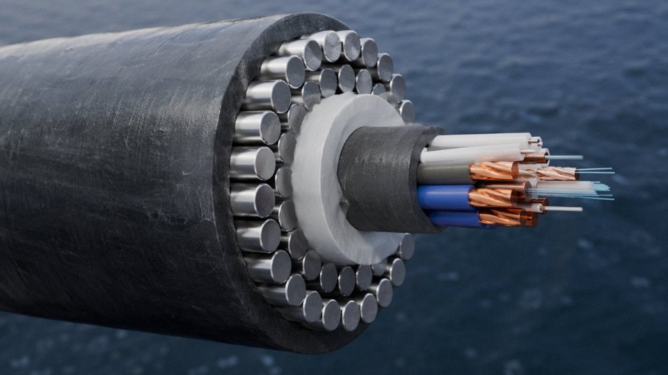
DSWA consists of two concentric helical layers of steel wires wound in opposite directions. The opposing helix is the key detail: it prevents the torque generated by one layer from propagating torsional stress into the cable core under tension, which matters enormously in vertical-drop applications. Tensile capacity for large DSWA cables typically falls in the 80–200 kN range, depending on cable diameter, wire gauge (usually 1.6–3.15 mm per wire), and number of wires per layer. For a 95 mm² three-core submarine cable, that tensile figure is what allows the cable to hang unsupported down a 400 m mine shaft without the armor birdcaging or the conductor geometry distorting.
Submarine power cables for offshore wind and inter-island grid connections use DSWA as the baseline armor configuration for water depths up to roughly 200 m. The outer armor layer handles trawl-drag and anchor-snagging loads; the inner layer provides crush resistance during cable-lay operations when the cable passes over a tensioner or sheave. Between the two armor layers, and beneath the inner layer, jute or polypropylene yarn bedding serves as both a corrosion buffer and a cushion that prevents wire-on-wire fretting. Galvanizing specification matters here — IEC 60227 or equivalent hot-dip galvanizing gives you a zinc coating mass of around 260–300 g/m², which is the practical minimum for long-term seawater exposure. Cheaper cables sometimes cut this to 180 g/m² or less. That’s a risk you’ll only discover five years into service.
Armored Mining Cables: Flexibility Under Punishment
A continuous miner trailing cable gets flexed thousands of times per shift. The cable follows the machine through tight radius turns — sometimes as low as 6–8× the cable OD — while simultaneously absorbing impact from falling rock and the physical weight of the machine passing over it. Standard SWA with relatively stiff individual wires would work-harden and fracture within weeks in that environment.
Mining trailing cables solve this with fine-wire stranded armor: individual armor wires are much thinner (often 0.5–0.9 mm diameter) and wound at a shorter lay length to preserve flexibility. Round trailing cables for longwall shearers and draglines typically carry double-wire armor for this reason, with the two layers again wound in opposition. Flat trailing cables, used where cable management trays are shallow, use an interlocked or woven armor profile to maintain flexibility in one bending plane. The insulation compound — usually EPR or heavy-duty PCP — is chosen for ozone and flame resistance, not just dielectric performance.
Fine-wire double armor on mining trailing cables provides both the flexibility for repeated tight-radius bending and mechanical protection against impact and abrasion simultaneously.True
The combination of small wire diameter (increasing flexibility) and double-layer opposing helix (providing tensile strength and crush resistance) is the established engineering approach used in mining cable standards such as IEC 60502 and AS/NZS 1660 for trailing cables.
Interlocked Armor and Corrugated Aluminum Sheath (CAS)
Common in North American installations and specified under standards like UL 1569 (MC cable), interlocked armor uses aluminum or steel strips formed into a continuous interlocking profile — think of the way a spiral binder folds — rather than discrete parallel wires. The result is a cable you can bend by hand in the field without tools and terminate with a simple knock-on fitting rather than a gland. That field-termination ease is a significant labor cost factor in commercial building wiring, where electricians may be making hundreds of terminations per floor.
The mechanical protection is decent but not comparable to DSWA or heavy SWA. Interlocked armor handles incidental impact, rodent damage, and installation abuse in conduit, but it’s not designed for direct burial under load or significant tensile stress. CAS (corrugated aluminum sheath) provides better moisture ingress resistance than interlocked aluminum strip and has some additional crush resistance due to the corrugated profile, making it the preferred choice for medium-voltage runs in industrial plants where the cable will pass through wet areas or be installed in cable trays subject to maintenance foot traffic.
Wire Braid Armor: Protection and EMI Shielding Combined
Instrumentation cables, thermocouple extension leads, and process control cables in refineries and chemical plants often specify braided armor rather than wire or tape armor. Fine galvanized steel or stainless steel wires — typically 0.15–0.30 mm diameter — are braided over the cable at an angle of roughly 45–55° to achieve coverage of 85–95%. Below about 85% coverage, the braid begins to lose useful EMI/RFI shielding effectiveness, particularly above 100 kHz, which is why specification sheets for instrumentation cable should always state the braid coverage percentage explicitly, not just the braid material.
In a petrochemical plant environment, the dual function is the real selling point: the braid provides physical protection against abrasion from cable tray edges and maintenance traffic while simultaneously acting as a Faraday shield for the signal conductors inside. Stainless steel braid is worth the cost premium in areas with H₂S exposure or where the cable routing passes through wet wash-down zones; galvanized steel braid will rust and lose coverage over 3–5 years in those conditions, which progressively degrades both the mechanical and EMI protection.
Application Mapping
| Cable Type | Typical Environment | Voltage Range | Flexibility | Common Standard |
|---|---|---|---|---|
| DSWA | Submarine, deep mine vertical shaft | Up to 33 kV | Low (fixed) | IEC 60502-2, BS 6622 |
| Mining trailing (fine-wire double armor) | Continuous miner, longwall, dragline | 1.1–11 kV | High (repeated flex) | IEC 60502, AS/NZS 1660 |
| Interlocked aluminum armor (MC) | Commercial building, light industrial conduit | 600 V–15 kV | Medium | UL 1569, NFPA 70 |
| Corrugated aluminum sheath (CAS) | MV industrial, wet areas, cable tray | 5–35 kV | Medium | ICEA S-93-639 |
| Wire braid (steel/SS) | Instrumentation, thermocouple, control | Signal–1 kV | Medium-high | IEC 60332, ISA-5.1 |
The selection logic across these types comes down to two axes: what kind of mechanical stress (tensile, crush, repeated flex, or abrasion), and whether EMI immunity is a simultaneous requirement. Getting that wrong — using interlocked armor in a deep mine shaft, for instance, or specifying SWA on a cable that needs to flex daily — will produce failures that look like random cable faults but are entirely predictable given the installation conditions.
Armored Cable by Application Domain: Power, Control, Instrumentation, and Fiber Optic
Armor type is only half the specification. Once you’ve decided between SWA, STA, and aluminum variants, you still need to match insulation system, shielding architecture, and conductor configuration to what the cable actually does in service. That integration — armor plus insulation plus shielding — is where most specification errors happen on real projects.
Armored Power Cables
The dominant construction globally is XLPE-insulated, SWA-armored, copper or aluminum conductor, rated from 0.6/1 kV up through 11 kV, 22 kV, and 33 kV. Voltage class drives everything above the conductor: at 0.6/1 kV you can get away without a metallic screen over the insulation; by 6.35/11 kV, a copper tape or wire screen becomes mandatory to control radial electric field stress and prevent partial discharge at the insulation surface. Insulation wall thickness scales accordingly — roughly 2.5 mm at 0.6/1 kV, climbing toward 8–10 mm at 33 kV depending on conductor size and applicable standard.
EPR insulation appears where XLPE’s relative stiffness is a problem — offshore platform cable trays that flex seasonally, or installations near oil and heat sources where EPR’s thermal tolerance to 90°C continuous (and short-circuit peaks above 250°C) justifies the cost premium. SWA dominates low- and medium-voltage power distribution because the helical wire construction handles both the tensile loads of vertical riser runs and the ground movement stresses in direct burial without the localized stress concentration you’d get from tape.
Armored Control Cables
Rated at 0.6/1 kV, multi-core (anywhere from 4 cores up to 61 in a single cable, sometimes more), these cables run between motor starter panels, relay logic systems, and SCADA marshalling cabinets. In practice, STA armor is common here because the runs are usually in cable trays or conduit rather than direct burial under mechanical load — crush resistance matters more than tensile strength when a 12-core control cable is bundled under three layers of other cables in a congested tray.
In plants with serious electrical noise — large VFDs, arc furnaces, or dense motor populations — an overall screened and armored construction (written as OS/SWA on the data sheet) becomes worth the added cost. The armor provides mechanical protection; the overall screen provides a low-impedance return path for induced noise currents. Skipping the screen and relying on armor alone for EMI control is a mistake that produces unexplained relay misoperations weeks after commissioning, not immediately.
Armored Instrumentation Cables
Instrumentation cables running 4–20 mA analog loops, thermocouple extension pairs, or RTD circuits operate at 300/500 V or less, but signal integrity — not voltage — is the engineering constraint. Individually screened pairs or triads (IS) plus an overall screen (OS) plus STA or wire braid armor is the standard construction for oil, gas, and petrochemical plant instrument loops. The individual screens prevent inter-pair crosstalk; the overall screen handles common-mode interference from adjacent power cables sharing the same tray; the armor handles the physical abuse of a working plant.
Individual pair screening alone, without an overall screen, is sufficient for 4–20 mA instrumentation cables routed near high-voltage power cables.False
Individual screening controls inter-pair crosstalk but does not adequately attenuate common-mode noise induced by adjacent power cables. IS/OS (individually screened plus overall screened) construction is the correct specification for mixed-tray industrial instrumentation runs, as reflected in IEC 60332 and plant engineering standards from major petrochemical operators.
Armored Fiber Optic Cables
Glass fiber has essentially zero tolerance for crush loads or sharp bends — a few hundred microstrain of mechanical stress translates directly into signal attenuation through microbending. Armor on fiber optic cable isn’t about voltage protection; it’s about keeping the fiber’s geometry intact.
Outdoor direct-burial fiber uses loose-tube construction (fibers floating in gel-filled tubes, which absorbs differential thermal expansion) with SWA or corrugated steel tape armor. The corrugated steel tape design — a longitudinally applied, corrugated steel strip — gives good crush resistance with a smaller outer diameter than wire armor, which matters when threading cables through conduits. Rodent damage is a real and underappreciated failure mode in rural and agricultural installations; steel armor stops it, aluminum tape mostly does not.
Indoor armored breakout cables use tight-buffered fiber, which makes termination easier, with a lighter wire braid or interlocked armor suited for industrial tray runs rather than direct burial.
Composite and Cross-Domain Cables
Offshore platforms, wind turbines, and rail signaling systems frequently specify composite cables — power cores, control pairs, and fiber optic elements sharing a single armored sheath. The logic is purely practical: running separate cable routes for each service costs more in tray space, installation labor, and penetration seals through bulkheads or fire barriers. A single well-specified composite cable with SWA armor and appropriate internal segregation of fiber and power elements handles all three services with one entry point.
Application Domain Selection Matrix
| Application Domain | Recommended Armor | Insulation Type | Shielding Requirement | Key IEC/ANSI Standard |
|---|---|---|---|---|
| LV Power (≤1 kV) | SWA or STA | XLPE or PVC | None typically required | IEC 60502-1 |
| MV Power (6–33 kV) | SWA | XLPE or EPR | Metallic screen (tape or wire) required | IEC 60502-2 |
| Control (multi-core) | STA or SWA | PVC or XLPE | OS/SWA for high-noise environments | IEC 60227, IEC 60502-1 |
| Instrumentation | STA or wire braid | PVC or XLPE | IS/OS mandatory for analog signal integrity | IEC 60332, IEC 61158 |
| Fiber Optic (direct burial) | SWA or corrugated steel tape | — | N/A | IEC 60794-1, ITU-T G.652 |
| Fiber Optic (indoor tray) | Wire braid or interlocked | — | N/A | IEC 60794-2 |
| Composite (power + fiber + control) | SWA | Mixed per core type | IS/OS on signal pairs | IEC 60092 (offshore) |
Getting the armor right but mismatching the shielding architecture to the application is one of the more common procurement errors on greenfield industrial projects — usually caught only during loop testing, at which point re-cabling a congested tray is an expensive problem to have.
How to Specify Armored Cable Correctly: Key Parameters, Standards, and Common Specification Errors
Getting the armor type right is only half the job. A surprisingly large share of cable failures and procurement disputes on international EPC projects trace back not to a wrong armor choice but to an incomplete or internally inconsistent specification — the wrong gland called out on the drawing, the outer sheath incompatible with the burial environment, or the armor’s earth-return short-circuit rating never checked at all. This section is a practical framework for avoiding those problems before they reach the plant floor.
Reading and Writing the IEC Cable Designation String
In IEC-based markets, a fully specified armored cable looks something like this: 3×95+1×50 mm² Cu/XLPE/SWA/PVC 0.6/1 kV. Each element carries a specific engineering commitment. Reading left to right: three 95 mm² main conductors plus one 50 mm² reduced neutral, copper conductor, cross-linked polyethylene insulation, steel wire armor, PVC outer sheath, rated for a 0.6 kV phase-to-earth / 1 kV phase-to-phase system. Drop any element and the document becomes ambiguous — and ambiguous specs generate RFIs, substitutions, and arguments about who owns the cost of a mismatch.
Aluminum conductors (Al) must be called out explicitly; silence is not permission to substitute. Same goes for insulation: EPR, XLPE, and PVC have meaningfully different thermal limits and chemical resistance profiles, and specifying only “armored cable” leaves the insulation open to interpretation.
Five Parameters That Must Be Fixed Before You Select Armor
- System voltage and insulation level. This determines the insulation class and, for medium-voltage cables, the screen or shield configuration. Armor selection follows; it cannot lead.
- Continuous current rating with derating applied. Burial depth, soil thermal resistivity, grouping factor, and ambient ground temperature all compress the current-carrying capacity — sometimes significantly. A 95 mm² copper XLPE cable rated around 220–240 A in free air might derate to 150–170 A when buried in a tight multiway duct, depending on grouping and soil conditions. Size conductors to the derated value, not the catalogue headline.
Mechanical threat profile. Tensile load along the route calls for SWA. Radial crush from vehicles or compacted backfill calls for STA or double armor. Repeated flexing in trailing cables requires flexible braid armor. Specifying the wrong armor for the dominant threat is the most expensive single error in this list.
Environmental conditions. Corrosive soils — high chloride, acidic pH, stray-current zones near DC transit systems — degrade steel armor faster than most engineers expect, sometimes within five to eight years in aggressive conditions. That’s where PE outer sheath and, in severe cases, aluminum armor or additional corrosion-resistant jacketing becomes the correct call rather than a cost upgrade.
Installation method and route constraints. Vertical risers and submarine pulls impose continuous tensile stress that STA simply was not designed for. Confined plant rooms and public transit infrastructure often mandate LSZH outer sheaths under local fire codes, regardless of what a generic project spec says.
Outer Sheath Selection Is Not a Footnote
The outer sheath’s primary structural job is protecting the armor from its environment. Standard PVC (ST2) covers most above-ground and moderate-burial applications. LSZH/LSOH is non-negotiable in tunnels, public buildings, offshore topsides, and anywhere toxic smoke density is regulated. PE outer — harder, less flexible, better chemical resistance — is usually the right call for direct burial in aggressive or waterlogged soils. The chemical compatibility of the sheath with the burial medium matters as much as the armor wire diameter.
The Five Specification Errors That Cause Real Problems
Single-core AC cables specified with SWA. Steel wire armor on a single-core AC cable creates a closed magnetic circuit around a single conductor, inducing circulating currents that generate heat and measurable losses. The correct armor for single-core AC cables is aluminum wire (AWA), which is non-ferromagnetic.
STA specified on high-tensile routes. Steel tape provides crush resistance; it provides almost no tensile strength. Specify STA on a long inclined pull or a submarine section and you may be pulling replacement cable within a year.
Armor bonding requirements absent from the cable schedule. Whether the armor is bonded at one end or both ends — and where it is earthed — directly affects induced voltage levels, touch potential, and fault current paths. Omitting this from the schedule means it gets decided on site, inconsistently.
SWA glands torqued onto STA cable. The clamping geometry of an SWA gland grips individual wires; it cannot grip the smooth overlap of steel tape effectively. This produces a terminated cable with poor mechanical retention and uncertain earth continuity.
Short-circuit rating of the armor never checked. In many distribution designs the armor doubles as the earth return conductor. The cross-sectional area of the armor wires needs to be confirmed against the prospective fault current and the upstream protection clearing time. IEC 60502 provides the calculation basis; it is routinely skipped in project specs.
Testing Requirements Worth Writing Into the Purchase Order
For LV cables: conductor DC resistance, voltage withstand, insulation resistance, armor tensile test, and a crush test are the baseline. For MV cables (3.6/6 kV and above), add partial discharge measurement and, for XLPE, a hot-set test confirming crosslink degree. Third-party factory acceptance test (FAT) reports with full material traceability — conductor alloy certification, armor wire mill certs, sheath compound batch records — are standard on serious international EPC contracts and worth requiring explicitly rather than assuming.
IEC 60502-1 and IEC 60502-2 are the primary standards governing LV and MV armored cable type testing respectivelyTrue
IEC 60502-1 covers cables up to 1 kV and IEC 60502-2 covers cables from 1 kV up to 30 kV; both are widely referenced in international EPC project specifications and are used as the testing basis by accredited third-party laboratories.
How Jinda’s Engineering Team Supports Specification Work
For international projects — particularly where the EPC contractor is working from a voltage class or installation scenario unfamiliar to their local cable experience — Jinda’s engineering team reviews project specifications directly, identifies conflicts or gaps in the cable schedule, and provides derating calculations calibrated to the actual burial and grouping conditions. That includes cross-checking armor short-circuit rating against the project’s protection coordination study, something that often surfaces late and expensively if left to procurement. Certified test reports, IEC type test certificates, and full material traceability documentation are provided as standard for supply into export projects, meeting the documentation requirements of most international EPCs without needing to chase them after order placement.
Installation Methods and Handling Practices That Preserve Armor Integrity
Armor is only as good as the installation around it. Specify the right cable, then drag it around a tight conduit bend or terminate it with an undersized gland, and you’ve already compromised what you paid for. This section covers the handling and installation practices that field engineers and contractors actually need — the kind of detail that rarely makes it into data sheets.
Minimum Bend Radius: Where Most Damage Happens Before the Cable Is Even Energized
SWA cable requires a minimum bend radius of roughly 8–12× the overall cable diameter; the exact multiplier depends on conductor size, number of cores, and whether the cable is being pulled under tension or simply laid. STA is a bit more forgiving in the bending plane — typically 6–8× — because the tape construction is continuous rather than discrete wires. Single-core large-section AWA cable is the most restrictive of all, often 15–20× overall diameter, because the aluminum wires work-harden quickly and will crack if bent sharply.
When you violate these limits, the armor wires don’t just look kinked. They create a stress riser on the bedding layer underneath, and over time that translates directly into insulation damage at that exact point — often not visible until the cable fails under load, sometimes years later. Mechanical damage of this kind is one of the more frustrating fault modes to diagnose because the damage site is buried.
Pulling Tension: A Simple Formula That Gets Ignored Too Often
Maximum pulling tension for copper-conductor armored cable is calculated as T = k × A × n, where A is conductor cross-section in mm², n is number of cores, and k is 50 N/mm² for copper (roughly 30 N/mm² for aluminum). A 4-core 95 mm² copper SWA cable, for example, has a pulling tension limit around 19 kN. Exceed that, and you permanently stretch the armor wires. Stretched wires don’t return to their original pitch — the armor loses mechanical integrity even though the cable looks fine externally.
In practice, the pulling tension limit is most often exceeded when rollers are spaced too far apart in long horizontal duct runs, or when contractors try to rush a pull on a cold morning when the outer sheath has stiffened.
Direct Burial: Soil Type Changes the Calculation
Minimum cover depth is 0.5 m for LV circuits and 0.9 m for MV in most regional standards, though some infrastructure projects specify 1.2 m as a blanket rule. Either way, bedding matters as much as depth. A 75–100 mm layer of fine sand or selected granular fill above and below the cable cushions it from point loading. In rocky ground, SWA’s tensile strength is genuinely useful — individual armor wires distribute load and resist penetration better than tape. In soft clay or waterlogged ground, STA performs adequately for burial depths under about 1 m, but the tape edges can corrode faster in aggressive soils without a robust outer sheath.
Tile and marker tape go above the upper sand layer, not directly on the cable. Separation from gas, water, and telecom services should be at least 300 mm horizontally in most codes, and crossings should be at 90°.
Termination and Gland Selection: The Leading Cause of Field Failures
This is where a surprising number of problems originate. SWA cable glands grip individual armor wires with a cone-and-ring clamping mechanism. STA glands use a different profile designed to clamp the tape edges. Use an SWA gland on an STA cable and you’ll get a weak mechanical grip, possible tape deformation, and an unreliable earth continuity path.
Gland size must match the cable’s outer sheath diameter, not the conductor size. It’s common to see a project spec calling for, say, a 50 mm² cable where the installer buys a gland rated for 50 mm² conductor area — and gets a poor fit because the overall diameter with armoring and sheath puts the cable in a different gland size bracket entirely.
Incorrectly sized or mismatched cable glands are one of the most common causes of moisture ingress and armor damage at termination points in armored cable installations.True
The gland is the primary mechanical seal and armor termination point; an ill-fitting gland fails to compress the outer sheath correctly, allowing water tracking, and fails to grip the armor wires or tape reliably, which can also break earth continuity.
Armor Bonding and Earthing: Multicore vs. Single-Core Rules Differ
For multicore SWA cables, armor is bonded and earthed at both ends. The induced currents in a balanced multicore system are low enough that circulating current through the armor is not a concern. Standard practice is to connect the armor earth at both the supply end and the load end gland, and to record the armor earth resistance during commissioning.
Single-core cables — large AWA conductors in MV circuits being the typical case — require single-point bonding at one end only, or cross-bonding in longer runs. With both ends bonded, the alternating magnetic field from the single-phase conductor induces a continuous circulating current in the armor, which causes resistive heating, energy loss, and in extreme cases thermal degradation of the insulation over time. The sheath voltage at the unearthed end must be calculated and verified to remain below the threshold set in the project spec, commonly 50 V in accessible areas.
Site Storage and Drum Handling: Small Habits With Real Consequences
Store drums upright on their flanges. Never lay a cable drum flat on concrete — the lower flange takes the full weight, deforms, and jams against the cable, and you also risk crushing the outer turns. XLPE-insulated armored cable should not be stored above about 50°C ambient for extended periods; in outdoor storage in hot climates, shaded storage is worth arranging. PVC outer sheaths degrade measurably with prolonged UV exposure — not dramatically over a few weeks, but a cable sitting on an outdoor laydown yard for three to four months in direct sun will show surface crazing.
When unspooling for installation, always pay off in the direction that unrolls the drum naturally — pulling from underneath the drum in the direction of lay. Reversing this induces a twist in the cable that builds up over the length of the run and, in armored cable, causes the armor wires to tighten or loosen around the core unevenly.
Frequently Asked Questions About Armored Cable Types
Can armored cable be used without conduit?
Yes — this is actually one of the core reasons engineers specify armored cable in the first place. SWA and STA cables are constructed specifically for direct burial, open tray, ladder rack, and exposed surface wiring without any additional conduit. The armor layer itself serves as the mechanical protection that conduit would otherwise provide.
That said, “without conduit” doesn’t mean “without thought.” SWA performs well in most direct-burial and cable tray applications. STA, with its overlapping tape construction, handles point-load crushing but offers less tensile resistance, so on long vertical runs or where significant longitudinal stress exists, SWA is still the right call even if conduit isn’t required.
Where conduit still makes sense even with armored cable: high-abrasion environments like production floors with frequent forklift traffic, or applications where the outer sheath will be repeatedly abraded by rock edges in a poorly bedded trench. In those situations, running SWA through a short section of HDPE conduit at road crossings or under machinery plinths is cheap insurance. It’s a judgment call, not a code requirement in most territories.
What is the difference between SWA and STA cable, and which should I choose?
SWA uses helically applied steel wires and provides genuine tensile strength — it resists pulling forces, suits long conduit-free runs, and works in vertical installations. STA uses two overlapping steel tapes and resists radial crushing loads extremely well, but offers almost no tensile capacity.
The decision rule is simple: if your cable will be pulled through ducting, suspended vertically, or run any meaningful horizontal distance without continuous support, use SWA. If it’s going into a shallow direct-burial trench in stable soil with no significant mechanical tension, STA is acceptable and often cheaper.
Why must single-core power cables use aluminum wire armor instead of steel wire armor?
Steel is a magnetic material. On a single-core AC power cable, the alternating current creates a changing magnetic field around the conductor. Steel wire armor encircling that conductor acts like a shorted transformer secondary — induced eddy currents circulate in the armor and generate heat. Depending on current magnitude and armor cross-section, this can reduce effective cable ampacity by roughly 15–30%, and in some documented cases the armor itself runs warm enough to accelerate insulation aging.
Aluminum is non-magnetic. Aluminum wire armor (AWA) does not participate in this inductive heating mechanism, so single-core cables retain their full rated ampacity. This is not optional engineering nuance — it’s why IEC 60502 and BS 5467 both call out AWA as the correct armor for single-core MV cables. Specifying SWA on single-core 11 kV feeder cables is a real and recurring specification error, usually caught at the factory if the manufacturer is paying attention.
Steel wire armor on single-core AC power cables induces eddy currents that reduce effective ampacity and generate excess heat in the armor layer.True
This is an established electromagnetic principle confirmed by IEC 60502 and widely documented in cable engineering references. The armor forms a closed magnetic circuit around a single current-carrying conductor, resulting in measurable inductive heating losses.
How do I identify armored cable type from the drum label or cable markings?
IEC convention prints the cable designation directly on the outer sheath at regular intervals — typically every 500 mm to 1 m. A standard marking reads something like: 0.6/1 kV, 4×95 mm² SWA XLPE/PVC, IEC 60502-1, followed by the manufacturer name and year of manufacture. The armor type code (SWA, STA, AWA) appears as part of the construction descriptor. On MV cables, voltage class (e.g., 6/10 kV or 12/20 kV) is always prominent.
The drum label — the physical tag on the reel flange — must additionally show: rated voltage, applicable standard, armor type, conductor material and cross-section, number of cores, total drum length (meters), gross and net weight, reel number, manufacturing date or batch code, and manufacturer details. For export drums, country of origin and HS code are normally included.
Jinda prints full IEC-compliant markings on all cable sheaths and provides a test report cross-referenced to the drum serial number for MV and export orders. If you receive a drum where the sheath marking is illegible or missing, that’s a quality flag worth raising before installation.
What certifications and standards should armored cable comply with for international projects?
The baseline for most international EPC work: IEC 60502 (power cables up to 30 kV), IEC 60228 (conductor classes), BS 5467 (armored cables with thermosetting insulation) and BS 6724 (armored cables with low-smoke, halogen-free sheaths for use in public buildings and confined spaces). Australian and New Zealand projects typically require AS/NZS 1802 series compliance. North American projects may reference ICEA S-93-639.
For project qualification, CE marking covers EU market access. REACH and RoHS compliance matters for projects with strict environmental clauses — most European utilities and data center developers now require formal declarations. Third-party certification from bodies like BASEC (UK), KEMA/DNV (Europe and offshore), or Bureau Veritas carries real weight on EPC shortlists; a manufacturer’s self-declaration alone rarely satisfies a major utility procurement specification.
Jinda holds IEC-based type test reports and can provide BASEC-certified product lines for UK and Commonwealth projects. Specific certification requirements should be flagged at enquiry stage, not after manufacturing has started.
What minimum order quantities and lead times apply for custom armored cable from Jinda?
Standard SWA and STA power cable in common sizes (4–6 core, 16–240 mm²) typically carries a minimum order of around 300–500 m per size. That range shifts depending on conductor cross-section and voltage class — a 3-core 95 mm² 11 kV SWA cable involves more material cost per meter, so the minimum is lower in length but similar in value. Genuinely custom designs — non-standard core counts, special sheath compounds, armored fiber composite cables — are priced and minimums set on a project basis.
Lead times for stock-range LV armored cables run roughly 15–30 days from order confirmation. Custom MV cables (6–33 kV with specific armor configurations or certifications) realistically need 45–90 days, and that window assumes no delays in raw material — copper and aluminum rod prices and availability genuinely affect scheduling. For large infrastructure orders, Jinda’s five production bases allow parallel manufacturing across facilities, which can compress delivery timelines meaningfully compared to single-site producers.
How is armored cable tested before shipment?
Routine tests on every production length include: conductor DC resistance (verified against IEC 60228 class limits), high-voltage withstand test on the insulation, and insulation resistance measurement. These are performed per IEC 60502-1 or -2 as applicable and documented in the test certificate shipped with each drum.
Type tests — which qualify the design rather than every production run — cover partial discharge (mandatory for cables 6 kV and above), bending tests, armor tensile and crush tests, flame propagation, and where specified, smoke density and halogen content. These don’t repeat per order but the reports should be available from the manufacturer on request.
For international EPC clients, Jinda offers witnessed factory acceptance testing (FAT) — a customer representative or their nominated third-party inspector attends the factory and witnesses routine tests on the specific drums being shipped. This is increasingly standard on large substation and renewable energy projects where the client’s project quality plan requires witnessed testing. Arranging FAT in advance avoids the delays that come from inspectors showing up with no prior coordination, which, in practice, happens more often than it should.