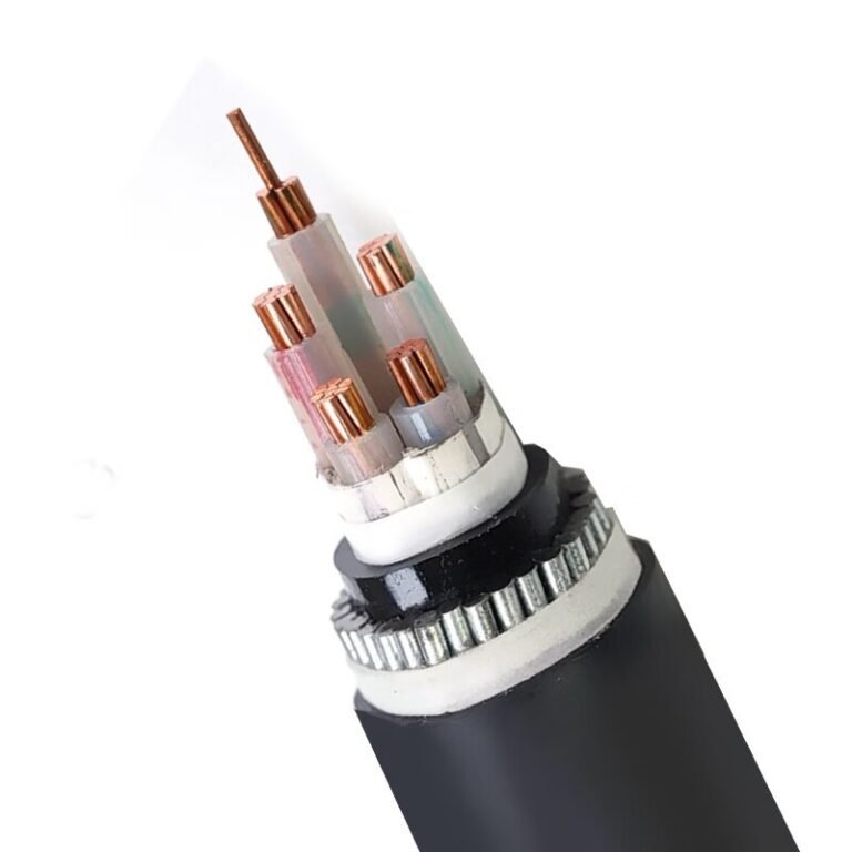
Someone on the maintenance crew grabs the nearest spool of cable to restore a tripped circuit before the line supervisor loses patience — and that spool happens to be a drum of 1.5 mm² control cable rated at 300/500 V. The repair gets done, the machine runs, and nothing trips immediately. Weeks later, the insulation browns and cracks under continuous load current it was never designed to carry, and now you’re looking at an unplanned shutdown, a potential arc fault, and an insurance conversation nobody wants to have.
A control cable should not be used as a power cable in any sustained load-carrying application. Control cables are rated for low-current signaling and switching circuits — typically 300/500 V or 450/750 V — with conductor cross-sections rarely exceeding 10 mm² and insulation designed for 70 °C continuous operation. Power circuits demand cables rated to carry full load current continuously, often at 0.6/1 kV or higher, with thermal ratings to match. Substituting one for the other risks insulation failure, fire, and equipment damage.
What makes this question harder than it looks is that the voltage numbers alone can be misleading — a 450/750 V control cable and a 0.6/1 kV power cable feel close enough that engineers sometimes rationalize the swap, especially under time pressure. The real gap is thermal and current-carrying capacity, and that gap doesn’t announce itself until the damage is already done. The sections below work through exactly where the specs diverge, what the failure modes actually look like, and the narrow edge cases where a technically sound argument for controlled substitution can be made.
Structural Differences Between Control Cables and Power Cables: Conductors, Insulation, and Shielding
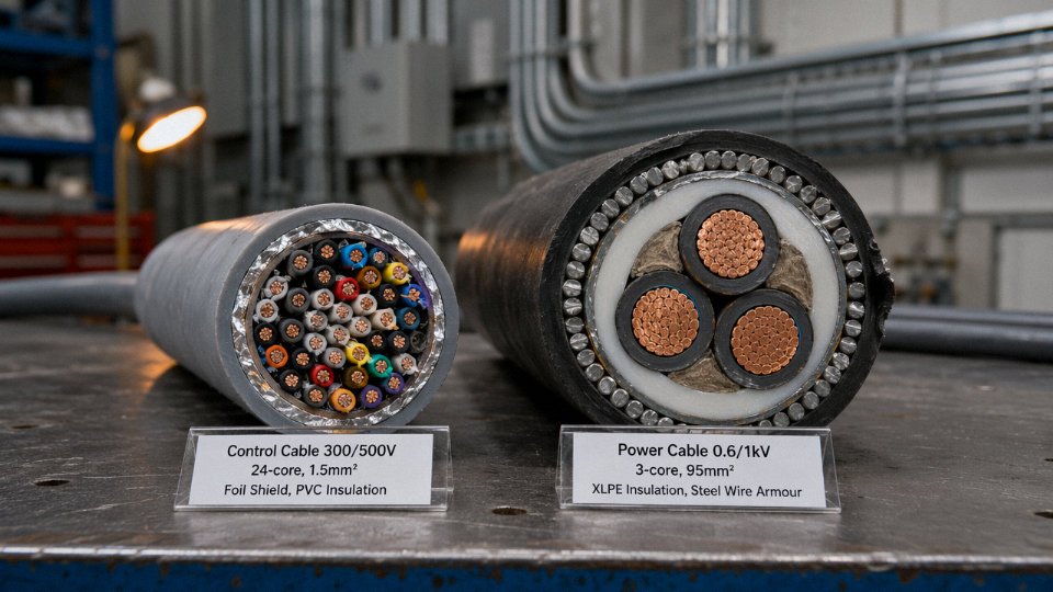
The two cable families look similar on a reel. Cut them open, and the engineering logic behind each becomes obvious — they were designed for fundamentally different electrical and mechanical duties.
Conductor Sizing Philosophy
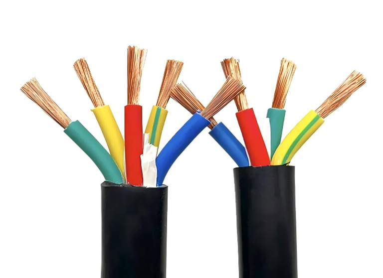
Control cables are built around signal integrity, not current capacity. A typical control cable carries interlock signals, SCADA feedback, solenoid pilot circuits, or pushbutton wiring — loads measured in milliamps to a few amps. That’s why conductor cross-sections run from 0.5 mm² up to roughly 6 mm² or 10 mm² in heavier-duty instrumentation cables. Many conductors, small gauge, tightly bundled.
Power cables do the opposite. Fewer conductors, each sized to carry full load current with an acceptable voltage drop over the run distance — which, in a plant setting, might be 200 m from an MCC to a pump. Cross-sections start at 1.5 mm² for lighting branch circuits and scale to 300 mm², 500 mm², even 630 mm² or larger for main feeder and transformer connections. The conductor sizing calculation involves load current, installation method, ambient temperature derating, and acceptable voltage drop percentage — not just “what fits in the conduit.”
Trying to push 40 A through a 1.5 mm² control cable conductor isn’t just a standards violation. The conductor heats, the insulation softens, and you’re looking at a thermal failure that may not trip a breaker fast enough to prevent jacket damage or a fire.
Insulation Voltage Class
Most control cables are rated 300/500 V or 450/750 V. Power cables start at 0.6/1 kV and scale to 3.6/6 kV, 8.7/15 kV, 26/35 kV, and well beyond for transmission-class applications.
Voltage class isn’t just a marketing label. It defines the insulation wall’s dielectric strength — its ability to resist breakdown under sustained voltage stress — and the required creepage distances at terminations. A 300/500 V rated insulation has a thinner dielectric wall and narrower safety margins. Put it on a 1 kV circuit and you’re operating outside the tested dielectric stress envelope. Partial discharge starts. Over weeks or months, treeing propagates through the insulation, eventually producing a ground fault or phase-to-phase failure, often at the worst possible moment.
A control cable rated 300/500V can safely replace a power cable on a 0.6/1kV circuit if the current is kept lowFalse
Voltage class and dielectric wall thickness are independent of current load. Even at minimal current, the insulation of a 300/500V control cable is not rated for the continuous voltage stress of a 0.6/1kV system, creating risk of insulation breakdown over time.
Insulation Material and Wall Thickness
Standard PVC-insulated control cable uses a compound optimized for flexibility, abrasion resistance, and ease of termination in cable trays and conduit. The continuous temperature rating sits around 70°C. That’s adequate for low-current signal duty.
Power cable XLPE (cross-linked polyethylene) or EPR insulation carries a 90°C continuous rating, and — critically — a short-circuit temperature tolerance up to around 250°C for XLPE. The insulation wall is physically thicker to handle dielectric stress, and the material itself is cross-linked at the molecular level, meaning it doesn’t soften and flow under fault conditions the way standard PVC does. EPR handles wet and high-temperature environments better still. These aren’t incremental upgrades. They’re different engineering platforms.
Shielding and Screening Layers
Many multi-core control cables include an overall foil-and-drain-wire shield, or individual pair shields in instrumentation grades. This shielding exists to reject EMI from adjacent power runs — the kind of interference that causes false trips in a relay or corrupted readings on a 4–20 mA loop. In a plant with VFD drives everywhere, this matters a lot.
The shield carries no load current. It’s bonded to ground at one end (usually) or both ends depending on the application. Some engineers see this metallic layer and assume the cable is “more robust” or “better protected.” It isn’t a structural reinforcement. It’s a Faraday cage for signal quality, and it contributes nothing to fault current capacity.
Jacket and Armor Construction
Outer jacket compounds differ in ways that matter for installation environment. Control cable jackets are generally softer PVC or LSZH compounds — easy to flex, suitable for cable trays. Power cable outer jackets tend to be heavier, with higher tear and impact resistance, because a fault on a 1 kV feeder releases far more energy than a faulted control signal conductor.
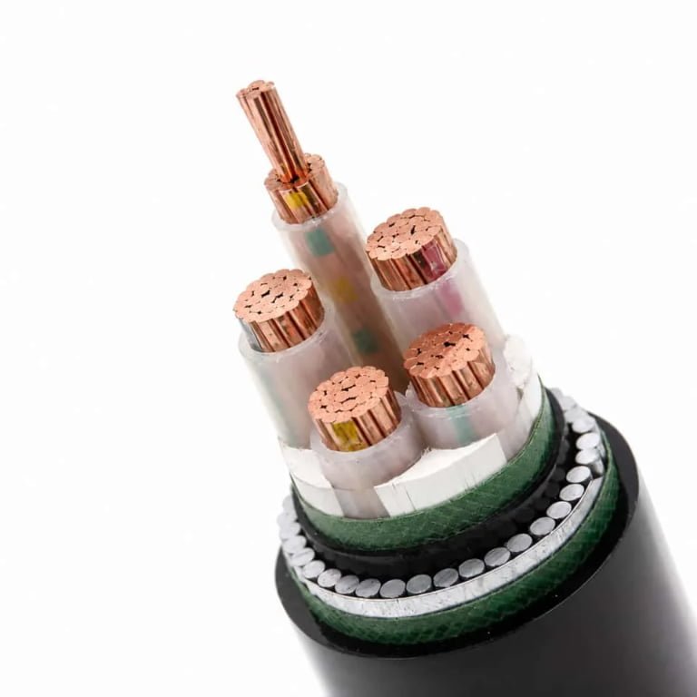
Armoring is where the difference becomes structural. Steel wire armor (SWA) or steel tape armor (STA) on a power cable is dimensioned partly against mechanical damage but also against the magnetic and mechanical forces that fault currents generate. A 3-core 95 mm² SWA power cable and a 12-core 1.5 mm² SWA control cable may look superficially similar in a trench, but the armor cross-section, the bedding thickness, and the jacket wall are all spec’d for different fault energy levels.
| Parameter | Typical Control Cable | Typical Power Cable | Consequence if Mismatched |
|---|---|---|---|
| Conductor cross-section | 0.5–10 mm² | 1.5–630 mm² | Overheating, insulation failure, fire risk |
| Voltage rating | 300/500 V or 450/750 V | 0.6/1 kV to 35 kV+ | Dielectric breakdown, insulation treeing |
| Insulation material | Flexible PVC, ~70°C rated | XLPE/EPR, 90°C continuous, 250°C fault | Thermal softening under load or fault |
| Insulation wall thickness | Thin (low dielectric stress) | Thick (engineered for voltage stress) | Partial discharge, premature failure |
| Shielding | EMI shield (foil/braid), not load-bearing | Usually unshielded; some screened MV cables | Shield misread as structural — no load benefit |
| Armor dimensioning | Light-duty, signal fault energy | Heavy-duty, power fault current forces | Armor failure during fault, injury risk |
| Typical conductor count | 4–61 cores, small gauge | 1–5 cores, large gauge | Wrong conductor count for load distribution |
The table above isn’t exhaustive, but it covers the failure modes engineers actually encounter when substitutions get made under schedule pressure. Each mismatch has a specific failure path — not a vague “safety concern,” but a predictable physical mechanism with a timeline.
Current-Carrying Capacity and Thermal Limits: What the Numbers Actually Mean
Ampacity — the maximum continuous current a conductor can carry without exceeding its insulation’s thermal rating — is not a fixed property of a wire. It depends on at least five interacting variables: conductor cross-section, insulation temperature class, installation method, ambient temperature, and how many other current-carrying conductors are bundled nearby. Change any one of those and the safe current limit shifts, sometimes dramatically. This is where the control-cable-as-power-cable substitution starts to unravel quantitatively.
Why Conductor Cross-Section Alone Doesn’t Tell the Whole Story
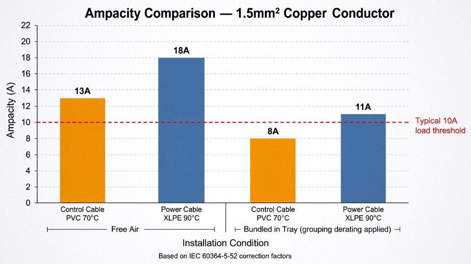
Take a 1.5 mm² copper conductor. In free air, as a single-core power cable with 90°C XLPE insulation, IEC 60364-5-52 would put its ampacity somewhere around 17–19 A depending on installation method and correction factors. Pull that same 1.5 mm² conductor into a 24-core control cable bundled in a tray with a dozen other cables, and the effective rating can drop to 10–13 A — occasionally lower if the tray is in a warm electrical room. The grouping derating factor alone, per IEC 60364-5-52 Table B.52.20, can reduce ampacity by 40–50% for cables in a tightly packed multicore bundle. Standard PVC-insulated control cables are rated to 70°C conductor temperature. Power cables with XLPE insulation are rated to 90°C continuous. That 20-degree difference sounds modest until you realize the thermal headroom above ambient is the entire margin the cable has before degradation begins accelerating.
The Thermal Failure Chain
The physics are straightforward and unforgiving. Excess current produces resistive heating proportional to I²R. In a control cable pressed into power service, that heat has nowhere to go fast enough — the tight multicore construction, PVC filler, and overall sheath all act as insulation in the thermal sense. The conductor temperature climbs. PVC insulation softens progressively above roughly 70°C; above 90–100°C it begins to flow and lose dielectric integrity. Early aging sets in long before visible damage appears. Dielectric breakdown follows — not necessarily as a dramatic arc, but often as a slow insulation resistance decline that eventually produces a ground fault or phase-to-phase short. In a cable tray, that fault can ignite the PVC jacket of adjacent cables. The fire investigators will find a cable that was never rated for the load it was carrying.
A 4mm² control cable conductor used as a 230V single-phase supply to a 2kW resistance heater draws approximately 8.7A, which appears well within the conductor's theoretical capacity.True
P = V × I gives I = 2000W ÷ 230V ≈ 8.7A. A 4mm² conductor in isolation can handle considerably more. The risk is not the steady-state current in ideal conditions — it is the combination of PVC insulation's lower thermal class, grouping derating in bundled trays, elevated ambient temperatures common near furnaces or in summer, and zero short-circuit withstand margin sized for power-circuit fault levels.
That scenario is the one that trips people up in practice. The numbers look fine on a napkin. They stop looking fine when the cable is routed through a 45°C machine room, bundled with nine other circuits, and the protective device is a 16A breaker that will not trip at 8.7A sustained.
Short-Circuit Withstand — the Margin Control Cables Don’t Have
Power cable conductors are sized not just for load current but for the adiabatic heating that occurs during a fault before the protective device clears it. The adiabatic equation — where conductor cross-section must satisfy S ≥ (I × √t) / k — assumes a specific k factor tied to conductor material and insulation type. For PVC-insulated conductors, k is lower than for XLPE; for control cable conductors in a multicore assembly, the thermal mass and heat dissipation path are worse still. A fault current of 1–3 kA lasting even 100–200 ms can raise a small conductor far beyond the insulation’s survival temperature. Control cables have no sizing margin for this. Power cables do, by design.
Ambient temperature compounds everything. Industrial plants near process heat — furnaces, dryers, compressor rooms — routinely see cable tray temperatures of 40–55°C. Every 10°C rise above the reference ambient (usually 30°C in IEC tables) requires another derating step. Stack grouping derating on top of ambient derating on top of a PVC thermal limit that was already the lowest in the cable family, and the actual safe current for a control cable in real plant conditions can be 30–45% below what the conductor cross-section suggests at a glance.
Voltage Rating, Insulation Integrity, and the Hidden Dielectric Risk
Overheating gets all the attention in these conversations, and understandably so — a hot cable is a visible, measurable problem. But the voltage mismatch issue is quieter and, in some failure modes, more insidious. Insulation that’s being stressed beyond its dielectric rating doesn’t smoke or trip a breaker. It degrades over months, invisibly, until it doesn’t.
What a Voltage Rating Actually Means
Under IEC conventions, a cable’s voltage designation is written as U₀/U — where U₀ is the rated voltage conductor-to-earth and U is the rated voltage conductor-to-conductor. A cable marked 300/500V has U₀ = 300V and U = 500V. That’s it. Nothing above those values is within the tested regime.
Standard control cables — the type you’d spec for a PLC panel or instrumentation loop — are typically 300/500V or, at the upper end of the control cable range, 450/750V. Power distribution in most industrial plants runs at 400V three-phase (TN-S or TN-C-S systems in IEC territories) or 480V in North American facilities. Phase-to-neutral on a 400V system is roughly 230V, which sits under that 300V U₀ figure and can tempt an engineer into thinking a 300/500V control cable is fine. It isn’t, and the conductor-to-conductor figure is exactly why: phase-to-phase is 400V, right at the U limit, with zero margin.
In NEC/UL frameworks the language is different — cables are rated 300V or 600V — but the underlying logic is identical. A cable rated 300V is not listed or tested for use on a 480V circuit, period. Inspectors know this. Insurance loss adjusters know this.
Transient Overvoltages: The Real Stress the Rating Has to Cover
Steady-state voltage is only part of what a cable’s insulation actually sees in service. Switching surges when contactors open under load, lightning impulse conducted through inadequately protected distribution boards, motor back-EMF during emergency stops, and — particularly punishing — the high dV/dt spikes generated by VFDs can push instantaneous voltage to 2–4 times the nominal line voltage for microseconds to milliseconds at a time.
Power cables are type-tested for impulse withstand voltage (Uimp). A 0.6/1kV power cable per IEC 60502-1 is tested at 6 kV impulse. A 300/500V control cable has a significantly lower Uimp — typically in the 2.5 kV range — and it was never designed or tested to handle the transient environment of a live power circuit.
A 450/750V rated control cable is safe to use on a 400V three-phase power circuit because the phase-to-neutral voltage of 230V is below the 450V U₀ rating.False
While 230V phase-to-neutral is below the U₀ rating, the phase-to-phase voltage of 400V sits at the cable's U limit with zero margin. More critically, switching surges, VFD dV/dt transients, and lightning impulse events can produce instantaneous overvoltages of 2–4 kV — well beyond the impulse withstand rating of a control cable, which was never tested for this transient regime.
Silent Degradation: Partial Discharge and Insulation Treeing
When insulation operates near or above its rated voltage, partial discharge begins — small electrical breakdowns in microscopic voids or surface irregularities within the PVC or XLPE compound. Each discharge event is tiny. Cumulatively, over weeks or months, the carbonized discharge tracks erode the insulation from the inside. In XLPE this manifests as electrical treeing, visible only under microscopy or with partial discharge detection equipment that most plants don’t run routinely.
PVC insulation in control cables is generally more susceptible than the XLPE used in rated power cables, partly because control cable PVC compounds are formulated for flexibility and abrasion resistance rather than optimized dielectric strength. The insulation wall thickness is also thinner by design. Both factors reduce the margin against sustained overvoltage stress.
The practical consequence: a misapplied control cable on a power circuit may pass initial installation checks, operate apparently normally for six to eighteen months, and then fail catastrophically — usually at the worst moment, often without clear prior warning signals on standard protection devices.
Compliance, Markings, and Insurance Exposure
Cable sheath markings aren’t just a manufacturer’s reference. The voltage designation printed on the outer jacket is a declared compliance statement tied to specific type-test reports. When an insurance assessor or a third-party electrical inspector reviews an incident, cable voltage class markings are one of the first things checked against the circuit’s rated voltage.
Using a control cable on a power circuit — even if the nominal voltages appear to align on paper — can void equipment insurance, invalidate installation certificates, and create personal liability for the engineer who specified or approved the installation. That’s not a theoretical risk. It’s a documented outcome in post-incident reviews across industrial sectors.
The 450/750V control cable on a 400V TN-S circuit scenario is probably the most common borderline case encountered in practice. Nominal voltages look close enough that someone makes the substitution, usually under time pressure. The phase-to-phase reality, combined with a VFD or a capacitor bank nearby generating transient spikes, means the cable is operating outside its tested envelope from day one. The degradation clock starts immediately; the failure shows up later.
International Standards and Electrical Codes That Prohibit or Restrict the Substitution
The technical case against using a control cable as a power cable is compelling on its own. But the regulatory case is what turns a bad engineering decision into a liability event — one that can void insurance, trigger enforcement action, and in serious incidents, land the approving engineer in front of a licensing board.
IEC 60227 and IEC 60502: Two Standards With No Intended Overlap
IEC 60227 covers PVC-insulated cables rated up to 450/750V. It governs flexible cords, light-duty wiring cables, and the types of multicore control cables you’d commonly find running to a PLC panel or a contactor bank. The standard defines conductor sizes, insulation thickness, and test voltages — all calibrated for signal-level or low-power-control duties.
IEC 60502 covers power cables from 1kV up through 30kV, with construction requirements — conductor class, insulation wall thickness, screen design, armoring options — scaled for sustained load current, fault current, and the mechanical stresses of installation in conduit, direct burial, or cable tray. The two standards describe fundamentally different products for fundamentally different duties. There is no provision in either document that authorizes a cable qualified under IEC 60227 to serve in a role that IEC 60502 governs. Using one where the other is required is not a gray area.
IEC 60364: Cable Selection Is Not Optional Engineering Judgment
IEC 60364-5-52 (Wiring Systems) requires that cables be selected based on voltage, current-carrying capacity, installation method, and ambient conditions — all of which must be verified against the manufacturer’s rated parameters. Section 4-43 on overcurrent protection requires that the protective device be coordinated with the cable’s actual rated capacity. A control cable substituted for a power cable almost certainly has a lower current rating than the upstream protective device is set to trip at, which means the cable can reach damaging temperatures before the breaker sees a fault. That is exactly the failure mode the standard is designed to prevent.
IEC 60364-5-52 requires that cable selection match the actual voltage, current, and installation conditions of the circuit — it does not permit 'equivalent' substitution based on physical similarity alone.True
IEC 60364-5-52 Table B.52 and the associated selection criteria explicitly require cables to be appropriate for the circuit voltage, load current, and installation method. No equivalence provision exists for substituting a lower-rated cable class.
NEC Article 725 vs. Article 310: A Listing Boundary You Cannot Cross
Under NFPA 70, Class 2 control cables (Article 725) are listed and tested for limited-energy circuits — typically circuits with power limited to 100VA or less. Using a listed Class 2 cable on a branch circuit governed by Article 310 violates the listing. The cable was tested and approved for one application; putting it in another doesn’t make it compliant, regardless of whether it physically fits in the conduit.
UL Listings and the Tray Cable Confusion
UL 508 listed control cable, UL 83 thermoplastic-insulated wire, and UL 1277 electrical power and control tray cable (TC) are three distinct listing categories. TC cable is a legitimate hybrid — it can carry both power conductors and control conductors within the same jacket — but it must still be UL 1277 listed specifically for that purpose. People sometimes see “tray cable” and assume any multicore cable in a tray is equivalent. It isn’t. A standard control cable run alongside power cables in an open tray is not the same as a TC-rated product, and using it that way fails the listing requirements under NEC 336.
CE Marking, the Low Voltage Directive, and the Technical File Problem
Under the European Low Voltage Directive 2014/35/EU, cable selection is part of the equipment’s technical file. If an installation uses cables not rated for the circuit voltage and load, the CE conformity declaration is compromised. In a product liability dispute or a post-incident regulatory audit, that technical file will be examined. An incorrect cable specification — even if the cable physically worked for months or years — creates a documented non-conformity that can invalidate the entire CE marking.
Insurance, Liability, and the Fire Investigation
This is where the stakes become personal. Fire investigators routinely pull cable samples from incident sites and send them for laboratory analysis. If a control cable is identified as the ignition source — or even as a contributing factor through excessive heating — and it can be shown that the cable was not rated for the load it was carrying, the insurer has grounds to deny the claim. More seriously, if the installation was signed off by a licensed engineer, that engineer faces potential professional discipline and, depending on jurisdiction, civil or criminal liability.
BS 7671 (the UK IET Wiring Regulations, 18th Edition) addresses cable selection in Appendix 4 and Regulation 523, both of which require that cables be appropriate for the current, voltage, and environmental conditions of the circuit. AS/NZS 3000 (the Australian/New Zealand Wiring Rules) contains equivalent requirements in Section 3.8, with explicit language that cables must be rated for the circuit they serve. Neither standard contains a carve-out for “temporarily using what’s available.”
The regulatory picture is consistent across jurisdictions: the substitution is not permitted, and the consequences of getting caught — usually after something has already gone wrong — are significant.
The Narrow Exceptions: When a Control Cable Can Legitimately Carry Power
Blanket statements — “never use a control cable for power” — are mostly correct but not always complete. There are genuine, code-supported scenarios where a control cable is technically adequate for a power duty. The key word is adequate: the voltage class, current capacity, and fault-level exposure all have to align, not just one of them. Miss any leg of that triangle and you’re back in hazardous territory.
Extra-Low-Voltage and SELV Circuits
The most defensible exception is 24 VDC control wiring, 12 V or 48 V DC auxiliary supply rails, and circuits that fall under IEC 61140’s SELV (Safety Extra-Low Voltage) or PELV definitions. A 300/500V-rated control cable is comfortably over-specified for the dielectric stress these circuits impose. At 24 VDC across a 0.75 mm² conductor carrying, say, 2–3 A to a PLC input card or a solenoid valve cluster, you’re well within both the voltage and thermal envelope.
That said, derating still applies. Bundling twelve control conductors in a trunking without airflow is not the same as running a single pair. Standard ampacity tables assume specific grouping factors — IEC 60364-5-52 correction factors for grouped cables can pull usable current down to 60–70% of the single-cable figure, depending on installation method. Apply those corrections before you sign off on anything.
IEC 60227 Flexible Multicore Cables for Light-Duty Instrument Supply
Some 300/500V flexible multicore cables manufactured to IEC 60227 are explicitly listed for both control functions and light-duty power supply to instruments or small panels — think a 230 V, 300–400 W instrument enclosure drawing under 2 A steady-state. The conditions that make this acceptable are fairly specific: the run should be short (generally under 10–15 m in practice), the circuit must be protected by a correctly coordinated MCB or fuse with a breaking capacity matched to the actual fault level at that point, and the cable must not pass through areas with elevated ambient temperature or mechanical abuse. A long run in a cable tray alongside heat-generating power cables quietly degrades insulation over time, even at low loads. This exception is not a license for casual reuse of leftover control cable from a panel build.
Tray Cable (TC-ER) in North American Installations
This is an important clarification worth stating plainly.
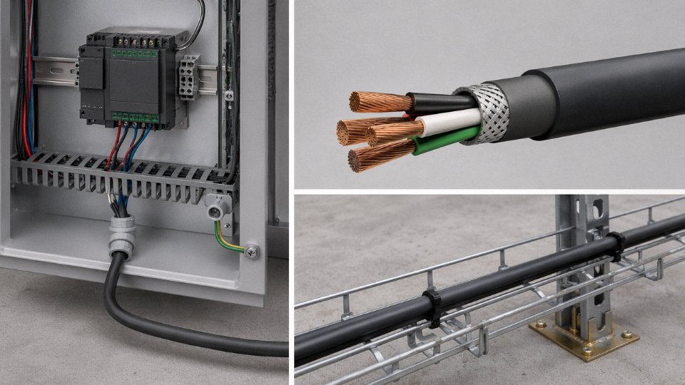
UL 1277 Tray Cable (TC-ER) is designed for combined power and control functions under NEC Article 336 and is not a repurposed standard control cable.True
TC-ER is a distinct product category engineered and listed specifically for power and control use in cable trays and raceways. It carries its own conductor sizing, insulation, and armor requirements — it is not equivalent to a standard IEC-style control cable being pressed into a power role.
If you’re working to NEC and your application calls for power and control in a single cable pathway, specify TC-ER from the start. Don’t pull standard control cable and assume tray installation makes it equivalent. The listing matters for insurance coverage and AHJ (Authority Having Jurisdiction) acceptance.
Temporary Commissioning Use Under Engineering Supervision
Some electrical codes — NEC 590 for temporary wiring, and similar provisions in IEC 60364-7-704 for construction sites — permit temporary use of cables not permanently rated for the duty, provided current is actively limited (typically via a variable transformer or current-limited supply), RCD/GFCI protection is in circuit, and the installation is under direct engineering supervision with a defined time limit. This is not a gray area you freelance. It requires written authorization, a current-limitation calculation on record, and a clear decommissioning date. In practice, most plant engineers I’ve seen use this provision during motor loop checks or instrument bench tests — not for extended commissioning periods.
Documentation Is Not Optional
Whichever exception applies, the paperwork burden is real. Written engineering justification, derating calculations referencing the applicable standard, confirmation of protective device coordination, and record retention are all required — both for internal quality systems and for any future insurance claim or incident investigation. A verbal OK from a senior engineer is not a substitution for a signed calculation sheet.
If a project genuinely needs a single cable to handle both power feed and control signals, the cleaner solution is a purpose-built combined power-and-control cable. Jinda’s multicore power-and-control range is engineered for exactly this duty — correct conductor sizing for the power cores, screened control pairs where signal integrity matters, and a single insulation system rated for the highest voltage class in the bundle. One cable, one set of installation documentation, no exception justifications to defend later.
How to Select the Right Cable for Mixed Power-and-Control Applications in Industrial Plants
Getting this right starts before you touch a catalog. Mixed power-and-control installations fail — slowly, then suddenly — when engineers treat cable selection as a single-pass task rather than two separate load analyses that happen to share the same tray.
Step 1 — Run Two Separate Load Lists, Not One
For every power circuit, work out full-load current, starting or inrush current (motor starting multipliers typically run 5–7× FLC depending on motor class and starting method), power factor, and expected voltage drop over the run length. Don’t accept nameplate FLC alone — check whether the load is a soft-starter, VFD, or DOL, because that changes the harmonic profile and therefore the thermal environment inside the cable.
For control circuits, list signal levels (4–20 mA, 24 V DC, 110 V AC, etc.), source impedance, and how noise-sensitive the device actually is. A hardwired permissive relay can tolerate interference that would corrupt a 4–20 mA analog loop. Keep these two lists physically separate in your spreadsheet. Mixing them is how people end up trying to justify running a control cable on a power circuit “just this once.”
Step 2 — Segregation Before Specification
IEC 61000-5-2 and IEC 60364-5-52 both require physical separation between power and control cables, and the intent is not bureaucratic — it’s to prevent inductive and capacitive coupling from injecting noise into sensitive circuits. In practice, 200 mm horizontal separation in an open cable tray is a commonly cited minimum, but that number assumes unshielded control cables. If you’re running shielded pairs, you can sometimes close that gap, though I’d verify with your panel builder before committing.
Dedicated conduit for control runs is the cleanest solution when retrofitting an existing plant where tray real estate is already contested. In new construction, specify dedicated tray zones — power on one level of a ladder rack, control on another — and enforce it during installation, because subcontractors will fill whatever space is convenient if you don’t specify otherwise.
Step 3 — Cable Tray Fill and Thermal Derating
This is where paper calculations diverge most from plant reality. Bunching derating factors from IEC 60364-5-52 (or NEC 310 if you’re in a US-code jurisdiction) can reduce ampacity by 30–50% in a fully loaded tray. Add an ambient temperature correction for a rooftop cable run in a facility located in a hot climate — ambient can hit 50–55 °C in summer — and a cable that looked adequate on a datasheet is suddenly marginal. Calculate tray fill ratio, apply the appropriate grouping factor, and verify the derated ampacity clears your full-load current with at least a 20–25% margin, because plants grow and circuits get added.
Step 4 — Purpose-Built Combined Cables Where Segregation Isn’t Practical
Some applications — compact machine panels, mobile equipment, flexible festoon systems — make physical segregation genuinely impractical. For these, purpose-built multicore cables conforming to IEC 60502-1 exist that integrate both power cores and individually shielded control pairs within a single outer jacket. The power cores carry the load; the screened pairs handle analog or digital signals with their own drain wire and foil or braid shield. Each pair’s shield terminates at one end only to avoid ground loops. This construction costs more per meter than running two separate cables, but it saves significant tray space and eliminates the routing coordination problem entirely.
IEC 60502-1 multicore cables can combine power cores and screened control pairs in a single jacket for installations where separate routing is impractical.True
IEC 60502-1 covers power cables with extruded insulation for rated voltages from 1 kV to 30 kV and permits multicore constructions; manufacturers produce combined power-and-instrumentation variants within this framework, with individually screened control pairs alongside power conductors.
Step 5 — Protective Device Coordination
The fuse or breaker must be coordinated with the cable’s actual derated ampacity — not the motor nameplate, not the load device rating, and definitely not “whatever was there before.” A control cable improperly used on a power circuit that survives for months usually fails catastrophically when an upstream protective device is oversized relative to the cable’s short-circuit withstand. Short-circuit withstand is a function of conductor cross-section and insulation type; PVC-insulated conductors have a significantly lower short-circuit temperature limit than XLPE, which affects the I²t rating your protection must not exceed.
Step 6 — Build and Maintain a Cable Schedule
A cable schedule is not paperwork for its own sake. Every circuit should carry an explicit record of voltage class, temperature rating, current rating, installation method, correction factors applied, and the applicable standard. That document becomes the baseline for commissioning inspection, insurance audit, and — critically — future maintenance when the engineer who designed the system is no longer on site. Cables get replaced with whatever is in the storeroom if there’s no schedule telling the maintenance tech what the spec actually requires.
Jinda’s technical support team regularly works through cable schedule reviews for international projects, helping procurement and engineering teams match products to IEC or project-specific specs, including multicore combined cables and screened instrumentation types. For complex or high-volume projects, that kind of early-stage coordination tends to catch substitution problems before they reach the installation phase.
Real-World Failure Cases and Lessons Learned from the Field
The technical arguments against substituting control cable for power duty are real, but abstract reasoning only goes so far. What follows are four anonymized field scenarios — three failures, one legitimate exception — drawn from the kind of situations that end up as insurance claims, OSHA citations, or very expensive rework orders.
Petrochemical Plant Cable Tray Fire
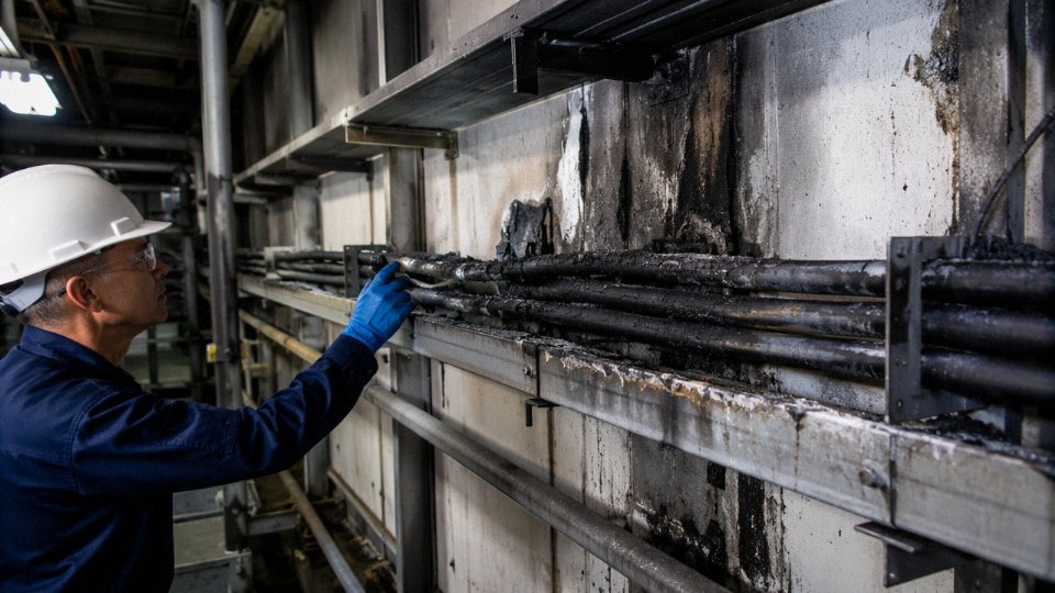
A maintenance crew needed to restore a 2.5 mm² circuit feeding a small pump motor — 230V single-phase, roughly 8–9A continuous. The original cable had been damaged during unrelated pipework. Stores had no power cable in stock, but there were several reels of 2.5 mm² multicore screened control cable sitting on the shelf. Same cross-section, same color, physically indistinguishable to anyone not looking closely at the drum label. They made the substitution and the pump ran fine.
Six months later, investigators were pulling charred cable from a tray that had sixteen other circuits bundled into it.
The root cause wasn’t the 2.5 mm² conductor per se — in open air, that gauge can carry the load. The problem was bunching derating. With sixteen circuits in a closed tray, the installed ampacity of that control cable dropped to somewhere in the range of 60–70% of its free-air rating, depending on tray fill and ambient temperature near that section of the plant. The control cable’s PVC insulation, rated to 70°C, had no margin left. It ran hot for months before the insulation softened, tracking began between conductors, and the resulting arc propagated into adjacent circuits.
The investigation cited IEC 60364-5-52 derating requirements, the absence of any engineering sign-off on the substitution, and the fact that the control cable was never listed for the service conditions on that tray. The plant’s property insurer disputed the claim on the basis of the unauthorized substitution. That dispute cost more than the rework.
VFD Drive Installation: Voltage Breakdown at Eight Months
A machine builder — doing nothing unusual, just trying to save a few days on procurement — used 450/750V rated multicore control cable as the power feed between a VFD and an 11 kW motor. The measured supply voltage was well within the cable’s rating. On paper it looked fine.
What the builder didn’t account for was the VFD’s switching transients. Modern IGBT-based drives can produce dV/dt values up to roughly 1,500 V/µs depending on the switching frequency and cable length, with reflected wave voltages that transiently reach two to three times the nominal DC bus voltage at the motor terminals. Standard PVC control cable insulation is not designed for repetitive high-frequency dielectric stress. Within eight months the insulation between phases had broken down, causing a phase-to-phase fault inside the conduit.
VFD switching transients can produce voltage spikes significantly exceeding the nominal supply voltage at the motor terminalsTrue
Reflected wave phenomenon in VFD installations causes voltage doubling at the motor end, with peak transient voltages potentially reaching 2–3× DC bus voltage depending on cable length, drive switching frequency, and impedance mismatch — well documented in IEC 60034-17 and drive manufacturer application guides.
The correct specification for that run was VFD-rated cable: XLPE insulation (90°C rated, better dielectric strength than PVC), symmetrical copper tape or braided shield for common-mode current management, and a voltage rating appropriate for the transient environment — typically 0.6/1 kV minimum for drives of this class. The rebuild cost roughly three to four times what the correct cable would have cost at procurement.
Offshore Platform Control Panel: Hazardous Area Listing Rejection
This one didn’t involve a fire. It involved a third-party inspection on a completed offshore module, five weeks before planned commissioning. The builder had used screened instrumentation-grade control cable for 24VDC power distribution rails feeding field transmitters in a Zone 1 hazardous area. Voltage-wise, the cable was fine — 300/500V rating against a 24V circuit. Electrically, nothing about it seemed wrong.
The inspector rejected the installation because the specific cable type was not certified for Zone 1 use under the applicable ATEX and IECEx documentation package. Adequate voltage rating does not equal hazardous area listing. These are entirely separate qualification axes, and confusing them is common.
Rework on a completed offshore module is expensive in ways that are difficult to overstate — confined spaces, hot work permits, scheduling against a commissioning window, the cost of personnel on the platform. Best estimates from similar situations put the direct rework cost somewhere between $80,000 and $200,000 depending on circuit count and accessibility, plus the schedule penalty.
Food Processing Plant: A Substitution Done Right
Not all of these end badly. A food processing plant needed a short power feed — 230V, 3A — to a small sensor interface unit mounted directly on a machine frame, total cable run under 3 meters. The electrical engineer specified a flexible 300/500V multicore control cable, documented the engineering justification in writing, confirmed the load was within the cable’s derated ampacity for that installation method, added RCD protection on the circuit, and got sign-off from the responsible engineer.
That substitution was defensible because someone actually did the analysis. The load was light, the run was short, the protection was adequate, and the documentation existed.
The Common Thread
In every failure case, the core mistake was the same: assuming that physical or nominal similarity meant functional equivalence. Same conductor size — must be interchangeable. Voltage rating looks adequate — must be fine. The successful case was different not because the cable was special, but because an engineer treated it as a deliberate decision rather than a convenience.
That distinction — analysis versus assumption — is what separates a defensible installation from a liability exposure.
Frequently Asked Questions About Using Control Cables in Power Applications
Can I use a control cable for 240 V single-phase power if its voltage rating is 450/750 V?
On paper, 450/750 V looks comfortable for a 240 V circuit. In practice, there are at least three separate problems that make this generally unacceptable.
First, bunching derating. Control cables typically run in multi-core bundles or packed trays. Ampacity tables for power cables already account for grouping factors, but a control cable’s conductor — often 0.75 mm² or 1.5 mm² — was sized for milliamp-range signaling loads, not sustained current draw. Run even 6–8 A continuously through a 1.0 mm² control cable core and you’re near or past the thermal limit of its 70 °C PVC insulation, especially once you apply a 0.6–0.7 grouping derating factor for a full tray.
Second, short-circuit withstand. Power-class conductors and their insulation are designed to survive fault currents for the duration it takes a breaker to clear — typically tens to hundreds of milliseconds. A control cable’s thin conductors have a significantly lower adiabatic withstand energy (I²t). If a downstream fault occurs, the conductor can fuse or the insulation can char before protection operates.
Third, code compliance. Most electrical codes require that wiring methods match the circuit classification. Satisfying the voltage number alone is not sufficient to pass inspection or satisfy your insurance carrier.
If you genuinely need a small 240 V circuit in a tight space, the right answer is a properly rated 0.6/1 kV flexible power cable, even if it’s only 1.5 mm². The cost difference is trivial compared to a wiring failure.
A 450/750 V control cable is automatically suitable for any circuit below that voltage.False
Voltage rating is just one parameter. Current-carrying capacity, short-circuit withstand rating, conductor cross-section sizing, and applicable installation codes all impose independent requirements that a control cable typically cannot satisfy for power duties.
What is the difference between a control cable and a tray cable (TC cable)?
A tray cable — defined under UL 1277 and referenced in NEC Article 336 — is a distinct listed product engineered for both power and control functions in cable trays. It carries specific conductor sizing minimums, jacket flame ratings, and ampacity assignments under tray-installation conditions. A standard IEC control cable installed in a cable tray is simply a control cable in a tray. The tray cable classification is a design and listing, not a location description. Don’t conflate them on a BOM or in a panel schedule.
Can the shield on a control cable serve as a protective earth conductor?
No. The foil or braid shield in a screened control cable is there to attenuate EMI — typically 0.1 mm aluminum/polyester foil or a sparse braid with maybe 60–85% coverage. Neither construction meets the cross-sectional area requirements for a protective conductor under IEC 60364-5-54, and neither has the fault-current thermal withstand you’d need if the shield had to carry a ground-fault current for even a fraction of a second. Use a dedicated green/yellow earth core. Always.
Are there control cables that are also rated for power use?
Yes, and this is worth knowing. Some manufacturers produce combined power-and-control cables — typically built to IEC 60502-1 — that include both full-rated power cores (0.6/1 kV, sized for real current loads) and screened instrumentation pairs within one overall jacket. These are specified by design intent and appear explicitly in the product datasheet as combined power-and-control constructions. They are not something you improvise by reinterpreting a standard control cable. If your application genuinely needs both power and signal in one run, specify the combined product from the start; retrofitting the interpretation later creates exactly the liability and compliance problems discussed throughout this article.
What happens to equipment certification and warranties if I substitute a control cable for a power cable?
Usually, everything unravels. A panel builder’s Declaration of Conformity under the Low Voltage Directive (or equivalent national framework) references the specific cable standards used in the build. Swap in a non-compliant cable type and the DoC is technically invalid. Equipment manufacturers write warranty terms that require wiring to comply with the installation standard cited in their documentation. An insurer reviewing a fire or equipment-damage claim will look at the installed wiring, and if the cable type doesn’t match what the standard requires, they have grounds to dispute the claim. This isn’t theoretical — it’s the kind of detail that surfaces during post-incident investigations.
How do I identify whether a cable is rated for power or control use?
Read the sheath print. Every compliant cable is printed with the governing standard, voltage class, temperature rating, and any relevant approvals. A legend reading “IEC 60227 300/500V 70°C” tells you it’s a low-voltage flexible control or light-power cable — not appropriate for a 400 V three-phase power circuit. A legend reading “IEC 60502-1 0.6/1kV 90°C XLPE” is a power cable. If the sheath print is worn off, abraded, or missing — which happens more than it should in busy warehouses — treat the cable as unidentified and don’t commission it into a power circuit until you can verify construction from supplier documentation.
Can Jinda supply a custom cable that meets both power and control requirements in a single product?
Yes. Jinda’s engineering team regularly develops combined power-and-control cable constructions for customers who need to minimize conduit fill or cable tray occupancy in large plants. The typical process starts with a technical intake: you provide the power core rating (voltage, current, fault level), the number and type of control pairs or triads needed, screening requirements, jacket material (based on environment — oil resistance, flame class, UV exposure), and any third-party approval requirements. From there, Jinda’s R&D team generates a construction drawing and datasheet for review before production. Samples are available for testing prior to bulk order commitment. For procurement managers sourcing for multi-site or long-term projects, Jinda can hold agreed-specification stock across its five production bases in China to support call-off schedules. Reach out with your specification and a qualified technical contact will respond — not a generic sales template.
Specifying the Right Cable From the Start: Jinda’s Approach to Power and Control Cable Engineering
Getting the cable specification right before procurement — not after the first commissioning fault — is where real project cost savings happen. A wrong substitution discovered during installation might mean a day’s rework. The same mistake found during a factory acceptance test, or worse, after handover, can mean weeks of delay, insurance complications, and the kind of liability conversation nobody wants to have with an EPC client.
A Product Range Built Around Real Project Schedules
Jinda’s manufacturing program covers the full width of what industrial and infrastructure projects actually need — not a curated subset. Control cables are produced to IEC 60227 and GB/T 9330, covering screened and unscreened multicore constructions from 0.5 mm² up through 10 mm², suitable for PLC panels, instrumentation loops, and motor control centers. Power cables follow IEC 60502-1 and -2 alongside GB/T 12706, running from low-voltage 0.6/1 kV distribution cables up through medium-voltage designs for substations and feeder circuits where the voltage and fault-energy levels genuinely demand the engineering investment in heavier insulation and larger conductors.
Beyond those core product lines, the range extends into areas that often trip up procurement teams on complex projects: combined power-and-control cables (one run doing both duties, properly engineered to handle both voltage classes and maintain signal integrity), VFD cables with the low-capacitance, symmetrical ground conductor geometry that variable-frequency drive applications require to control reflected voltage and bearing current issues, and instrumentation cables with individual and overall shielding suitable for 4–20 mA loops in electrically noisy plant environments. Specialist constructions for offshore and marine applications, oil and gas installations requiring flame-retardant or mud-resistant jackets, rail traction and signaling requirements, and solar/wind generation balance-of-plant work are all part of the regular production schedule — not special-order anomalies.
How the Technical Review Process Actually Works
When a customer submits a cable schedule or a project specification, Jinda’s engineering team works through the key parameters systematically: voltage class, continuous current and short-circuit rating, installation method (buried direct, in conduit, cable tray, open air, underwater), ambient temperature and thermal resistivity of the soil if relevant, applicable standard or approval (IEC, NEC, BS, AS/NZS, or local GB requirement), and any special environmental or regulatory demands — SIL rating for safety-instrumented systems, for instance, or Lloyd’s Register certification for marine work.
That review is provided at no charge for qualified project inquiries. In practice, it catches mismatches — a control cable specified where a power cable is needed, or a standard PVC jacket specified for an environment where a halogen-free flame-retardant compound is required — before they become procurement problems.
Jinda provides free cable schedule technical reviews for qualified industrial and infrastructure projects.True
This is a standard pre-sales engineering service offered by Jinda to support specification work for EPC contractors and procurement teams on qualified project inquiries.
Manufacturing Scale and Quality Infrastructure
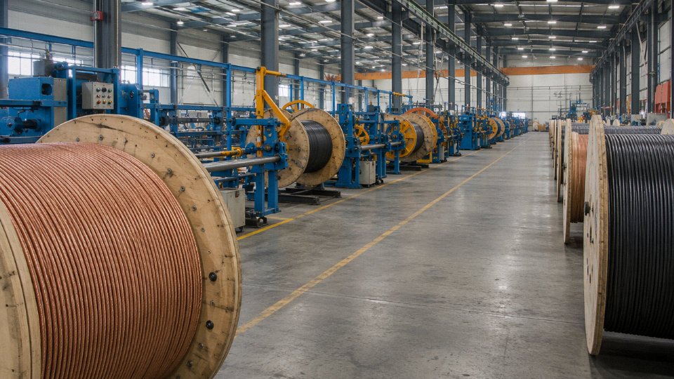
Five production bases across China, roughly 470,000 m² of total manufacturing space, and a workforce of over 1,000 people means Jinda can absorb large-volume orders without the lead-time compression that causes quality shortcuts. In-house testing laboratories carry IEC and GB standard test capability — conductor resistance, voltage withstand, insulation resistance, flame propagation, and mechanical tests — which matters when a customer’s inspection plan requires witnessed factory acceptance testing. Export certifications including CE marking and UL listings support delivery into regulated markets without the customs and approval delays that non-certified product can generate.
Raw material sourcing — oxygen-free copper rod, XLPE compound, PVC compound in the specific formulations that meet flame and smoke requirements — is managed through established supplier relationships, which keeps material quality consistent across production batches. That consistency is what procurement managers actually rely on when they’re placing repeat orders over a multi-year project.
Working With Jinda
If you’re an engineer finalizing a cable schedule, a procurement manager comparing specifications, or an EPC contractor locking down a supply chain for a major project, the practical next step is straightforward: share your cable schedule or project specification, ask for product datasheets on the specific construction you need, or request a technical review of an existing specification where you’re uncertain about the cable selection. Jinda’s commercial and engineering teams handle inquiries from customers in more than 50 countries and are experienced with the documentation requirements — test reports, material certificates, country-of-origin paperwork — that international procurement demands. The goal is a long-term supply relationship, not a single transaction.