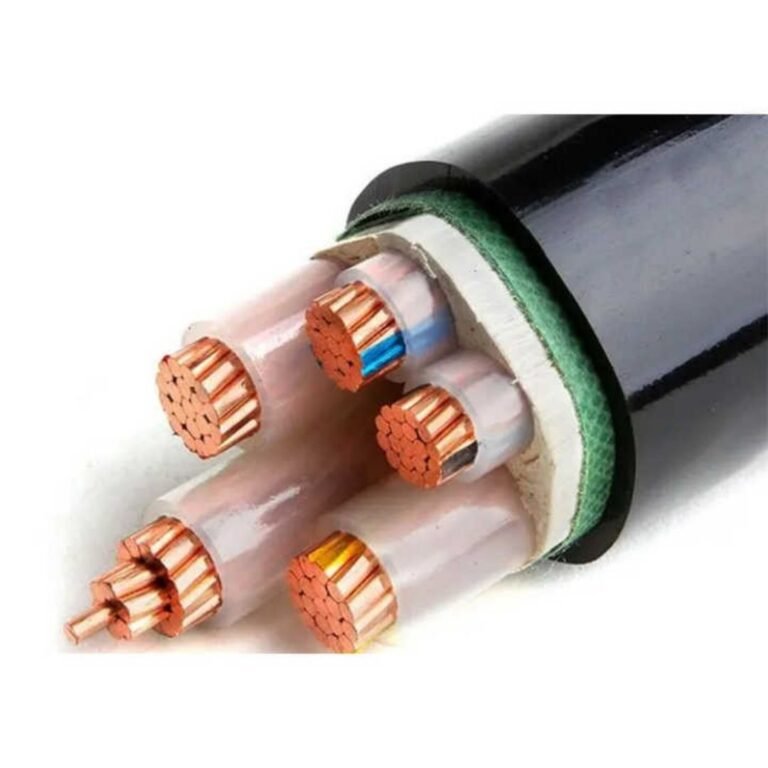
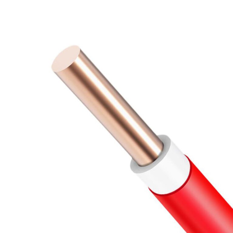
You plug in a cable, the device shows a slow-charge icon, the meeting starts in forty minutes, and nobody can tell you why the laptop is pulling 5W instead of 65W. That scenario plays out constantly — on factory floors, in procurement offices, in field service kits where cables from a dozen different projects have been pooling in the same drawer for three years. Misidentified cables cause more than frustration. They cause failed EV charging sessions, damaged battery management systems, and in industrial settings, unplanned downtime when a machine controller won’t handshake because someone swapped in a charge-only cable that has no data lines. The fix is straightforward once you know what to look for, but the connector landscape has fragmented enough that visual inspection alone doesn’t get you all the way there.
To identify your charging cable type, check the connector shape first: USB-A is the flat rectangular plug, USB-C is the small oval that inserts either way, Micro-USB is the trapezoid with angled lower corners, and Lightning is the thin rectangular Apple proprietary connector. For power cables — EV or industrial — look for a rating label on the moulded plug housing or a printed specification on the cable jacket. The connector shape tells you compatibility; the wire gauge and any embedded chip or e-marker determine how much power the cable can actually carry safely.
What most engineers and procurement teams don’t realize is that two cables with physically identical connectors can have completely different electrical capabilities — one USB-C cable might top out at 60W while another, visually indistinguishable, is rated for 240W under USB PD 3.1. The difference lives inside the connector housing, in a small IC called an e-marker, and in the conductor cross-section. Getting that wrong at scale, across a bulk procurement order, means you’re either under-specifying and throttling your equipment or — worse — over-stressing cables that weren’t built for the current you’re pushing through them.
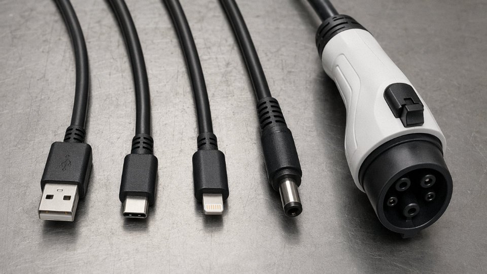
Reading the Physical Connector Shape: A Field Guide to Every Common Charging Plug
Before you reach for a multimeter or squint at faded label text, the connector shape itself tells you most of what you need to know. Each plug standard has a distinct geometry — and once you’ve handled a few hundred cables on a factory floor or in a procurement warehouse, you start recognizing them the way a machinist recognizes thread pitches by feel.
USB-A (Type-A)
The flat, rectangular plug. The opening measures roughly 12 mm × 4.5 mm, four pins inside, and it only inserts one way — which everyone has learned the hard way at least twice. Still dominant on charger bricks shipped before 2022, virtually every power bank made before 2023, automotive USB ports, and anything designed before the USB-C wave arrived. It tops out at around 18 W under Qualcomm Quick Charge 3.0, though most legacy USB-A ports deliver a much more modest 5 W at 2.4 A.
USB-B (Type-B)
Square body with two beveled top corners — almost looks like a little house shape. You’ll find it on desktop printers, older Arduino-compatible boards, and quite a few medical equipment chargers where the locking friction fit was considered more reliable than Micro-USB. Rarely seen on anything shipped after 2018, but it keeps showing up in industrial and clinical environments where equipment replacement cycles run ten to fifteen years.
Micro-USB (Micro-B)
Trapezoidal, asymmetric, five pins, and genuinely hard to insert in dim lighting because one side of the trapezoid has a slightly steeper angle than the other. Still the default connector on a large share of budget Android handsets, most Bluetooth peripherals under about $30, industrial wireless sensors, and warehouse scanners. The connection point is a known weak spot — the solder pads on the PCB side tend to fatigue after a few thousand insertion cycles, which is why cheap Micro-USB cables develop intermittent faults at the device end rather than the charger end.
USB-C
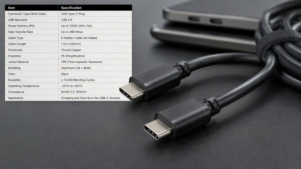
Oval, 8.25 mm × 2.4 mm, 24 pins, fully reversible. This is the one that changed the market. Under USB Power Delivery 3.1, a properly rated USB-C cable can carry up to 240 W — compared to 18 W for the best USB-A scenario. The EU mandate requiring USB-C on portable electronics sold in member states took effect in late 2024 for most device categories, which has pushed even holdout manufacturers to transition. That said, not all USB-C cables are equal: a cable that looks identical to a 240 W-rated one might be wired for 5 V/3 A only. The e-marker chip inside the plug determines actual capability, and you cannot see that from the outside.
USB-C cables support up to 240W charging under the USB PD 3.1 specificationTrue
USB Power Delivery 3.1, ratified by the USB Implementers Forum, extended the maximum power delivery to 240W (48V at 5A) for full-featured USB-C cables with an e-marker chip, up from the previous 100W ceiling under PD 3.0.
Lightning (Apple Proprietary)
Eight pins, slim profile, reversible. Physically smaller than USB-C and noticeably more delicate-looking. Found on iPhone 14 and all earlier iPhone models, older AirPods cases, and some Apple accessories like the Magic Keyboard and Magic Mouse. Apple has been transitioning away from Lightning since the iPhone 15 series, but given how long people hold onto Apple accessories, these cables will be in procurement lists for years yet.
DC Barrel Connectors
Cylindrical plug, no pins visible from outside, identified entirely by outer and inner diameter. Common sizes run from 3.5 mm outer / 1.35 mm inner up to 5.5 mm outer / 2.5 mm inner, with the 5.5/2.1 mm and 5.5/2.5 mm variants covering most laptop power bricks, routers, CCTV cameras, and embedded system power supplies. A 0.4 mm mismatch on the inner pin is enough to cause intermittent contact — something that causes mysterious reboots and takes an embarrassing amount of time to diagnose if you’re not thinking about it.
Operational warning: Never assume a barrel connector that physically fits is the correct one. Polarity (center-positive vs. center-negative) and voltage rating must match. A center-negative supply into a center-positive device will kill it quietly and immediately.
SAE J1772 / IEC 62196 Type 1 and Type 2
These are the Level 1 and Level 2 AC EV charging connectors. J1772 (Type 1) is a five-pin round connector used primarily in North America and Japan. IEC 62196 Type 2 is the seven-pin European standard with a flat top edge. Both use mechanical locking during charging. Conductor cross-sections in these cables range from roughly 1.5 mm² for low-current pilot signal wires up to 50 mm² for the main power conductors at high-current Level 2 installations — and that range depends entirely on the rated current and cable run length.
CCS and CHAdeMO
DC fast-charge connectors. CCS (Combined Charging System) adds a two-pin DC cluster below the standard AC connector base — so a CCS2 plug looks like a Type 2 with two extra large pins bolted underneath. CHAdeMO is a separate large-diameter round connector with five pins and its own locking collar, developed by a Japanese industry consortium. The two systems are physically incompatible and not interchangeable by any adapter that exists in normal commerce.
Quick Reference Table
| Connector | Pin Count | Max Rated Voltage | Max Rated Current | Primary Device Category |
|---|---|---|---|---|
| USB-A | 4 | 5 V (standard) | 2.4–3 A | Chargers, power banks, automotive ports |
| USB-B | 4 | 5 V | 0.5–0.9 A | Printers, Arduino, medical equipment |
| Micro-USB (Micro-B) | 5 | 5 V | up to 3 A (USB 3.0 variant) | Budget smartphones, sensors, accessories |
| USB-C | 24 | up to 48 V (PD 3.1) | up to 5 A | Laptops, phones, tablets, peripherals |
| Lightning | 8 | 5 V | up to 3 A | Apple devices pre-iPhone 15 |
| DC Barrel | N/A | 5–24 V (typical range) | 1–10 A (size and rating dependent) | Routers, CCTV, embedded systems, laptops |
| SAE J1772 / IEC 62196 T2 | 5 / 7 | up to 250 V AC | up to 32–80 A (Level 2) | EV AC charging |
| CCS1 / CCS2 | 7 / 9 | up to 1,000 V DC | up to 350–500 A | EV DC fast charging |
| CHAdeMO | 5 | up to 500 V DC | up to 400 A | EV DC fast charging (Japanese standard) |
Voltage and current figures are maximums per published specifications; actual delivered values depend on the specific cable rating, vehicle onboard charger, and EVSE capability.
Decoding Cable Markings, Stamps, and Certification Logos on the Jacket
The packaging is long gone. The cable came in a bundle, or a colleague handed it over, or it arrived as part of a bulk shipment with no documentation. That is the normal situation on most plant floors and in most households. Fortunately, the cable jacket itself carries a surprising amount of specification data — if you know where to look and what you are reading.
Certification Marks and What They Actually Guarantee
UL (Underwriters Laboratories) markings appear as “UL Listed” or the circular UL logo, usually printed in repeating text along the jacket every 150–300 mm. A UL listing means the cable construction passed defined flammability, voltage, and temperature tests — it does not automatically mean the cable will perform at its rated amperage indefinitely, especially in a hot enclosure. CSA marks serve a similar function for the Canadian market and are often printed alongside UL on cables sold into North America. CE marking is self-declared by the manufacturer for the EU market; it covers a basket of directives (LVD, EMC, RoHS) but involves no mandatory third-party test for most cable categories, so it tells you less than UL or TÜV does. RoHS compliance is frequently noted as “RoHS” or “RoHS Compliant” in the jacket print string, indicating restricted hazardous substances — relevant if you are procuring for the EU or for any electronics assembly environment. TÜV marks (from TÜV Rheinland or TÜV SÜD) carry more weight than CE for EV and high-power applications because they require witnessed testing; look for the TÜV diamond logo, usually molded or printed near the connector overmold rather than along the cable run.
Breaking Down the Jacket Print String
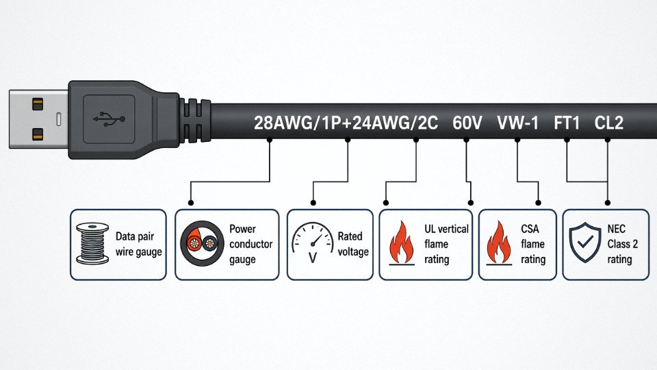
A typical USB cable jacket might read: 28AWG/1P+24AWG/2C 60V VW-1 FT1 CL2. Each segment means something specific. “28AWG/1P” identifies the data pair: 28 American Wire Gauge conductors in one twisted pair. “24AWG/2C” identifies the power conductors: two 24 AWG wires, which is what determines whether the cable can handle higher charging currents — a cable stamped 28AWG throughout is a data-only or very low current cable, full stop. “60V” is the rated voltage. “VW-1” is the UL vertical flame rating, meaning the cable passed a vertical flame test — relevant if the cable runs near heat sources. “FT1” is the Canadian Standards equivalent flame rating. “CL2” is the NEC Class 2 rating, allowing in-wall installation up to certain power levels.
A magnifying glass helps. On thin cables, particularly 28 AWG data-only USB-A types, the embossed text can be nearly illegible. A smartphone macro lens or a 10× loupe from any electronics supplier will make this readable in under a minute.
USB-IF Certification and the Trident Symbol
The USB Implementers Forum certifies cables through tested compliance, and certified cables carry the trident logo — a small stylized symbol resembling a three-pronged fork. On USB-C cables rated for higher wattage, you may also see “USB 2.0,” “USB 3.2,” or “240W” adjacent to the trident. Cables that lack the trident have not been tested to USB-IF specs.
Uncertified USB-C cables have caused device charging port failures and, in documented cases, component damage due to incorrect e-marker chip behavior.True
The e-marker IC embedded in compliant USB-C cables communicates power delivery parameters to chargers and devices. Uncertified cables frequently omit or misconfigure this chip, causing voltage or current negotiation errors that can damage charging controllers over time.
In practice, roughly half the generic cables sold through unbranded online listings carry no trident mark. That number is not a guess — anyone who has audited a cable procurement batch has seen it.
MFi Marks for Apple-Certified Accessories
Apple’s MFi (Made for iPhone/iPad) program licenses manufacturers to produce Lightning and USB-C cables that meet Apple’s electrical and firmware requirements. Genuine MFi cables display the “Made for iPhone” or “Made for iPad” badge on packaging, but on the cable jacket itself, look for a small Apple MFi logo near the Lightning connector overmold — it may be quite small, roughly 4–6 mm, depending on the mold. Cables without it may charge intermittently, trigger “This accessory may not be supported” warnings, or simply fail after a few weeks as the device firmware flags unauthenticated accessories.
EV Charging Cable Stamps: IEC 62196 and SAE J1772
EV charging cables operate at a completely different scale. IEC 62196 (common in Europe and international projects) and SAE J1772 (North America) govern the connector and cable standards. The cable jacket on a compliant EV cable will be stamped with the rated current — typically 16 A, 32 A, or 63 A for AC charging — along with a temperature class such as “T4” or “T5,” indicating the maximum sustained operating temperature. Conductor cross-sections range from roughly 1.5 mm² for pilot and ground conductors up to 50 mm² for high-current DC fast charge cables, and that cross-section is sometimes stamped directly on the jacket alongside the current rating. If it is not, that is a flag worth investigating before you install the cable.
Spotting Counterfeits by Their Markings
Counterfeit cables are a real procurement risk, particularly for high-volume USB-C and Lightning cable orders sourced through unverified channels. The markings are where they often slip up. Common misspellings to watch for: “LISYED” instead of “LSZH,” “UL Listed” rendered as “UL Listd” or “UL Llsted” (that second L is not a typo — it is a known counterfeit tell), and CE marks where the C and E are spaced incorrectly, making them resemble a different logo entirely. Some counterfeits stamp “RoSH” instead of “RoHS.” These are not subtle if you are looking for them. The general pattern is that legitimate jacket printing is crisp and consistent in spacing; counterfeit printing often has irregular character spacing or ink bleed, especially on curved overmold surfaces.
If a cable is missing certification marks entirely on a jacket that should carry them, treat that as a rejection-level finding, not a minor concern.
Using a Multimeter and Visual Cross-Section Inspection to Confirm Wire Gauge and Construction
External markings tell you what the manufacturer wants you to know. A multimeter and a sharp blade tell you what’s actually inside.
AWG vs. mm² — Why the Conversion Matters on the Bench
Most North American cable specs use AWG; most international datasheets use mm². The two systems run in opposite directions, which trips people up: a higher AWG number means a thinner wire. The conversions you’ll use most often for charging cables are 24 AWG ≈ 0.205 mm², 20 AWG ≈ 0.519 mm², and 18 AWG ≈ 0.823 mm². In practical terms, a USB cable built with 24 AWG power conductors is fine for data and low-current charging — say, 0.5 A to 1 A — but if you’re pushing 3 A through a 24 AWG VBUS line over a 2-meter cable, you’re going to see meaningful voltage drop and heat. Thin wire in a long cable is one of the most common reasons a USB-C charger shows 65 W on the adapter side and delivers noticeably less at the device.
Measuring Resistance per Meter to Estimate Conductor Size
Set your multimeter to its lowest resistance range — 200 Ω on most benchtop units is fine, though a true four-wire Kelvin measurement is more accurate if you have the gear. Short one end of the cable by bridging VBUS to GND with a small jumper, then measure across the same two pins at the other end. Divide by two (you’re measuring the loop resistance of both conductors) to get the single-conductor resistance, then divide again by cable length in meters. Copper at 24 AWG runs roughly 84 mΩ/m; 20 AWG drops to around 33 mΩ/m. If your calculated figure is significantly higher than expected for the claimed gauge, the conductor is undersized, contaminated with aluminum fill strands, or both. Cheap cables blended with aluminum-clad copper are a known problem in budget USB-C products — the resistance test catches them.
A USB cable rated 24 AWG for its power conductors will have a single-conductor DC resistance close to 84 mΩ/m for pure copper at 20°C.True
This follows directly from the resistivity of annealed copper (approximately 1.72 × 10⁻⁸ Ω·m) and the cross-sectional area of 24 AWG (0.205 mm²). Temperature and alloy purity shift this value slightly, but 84 mΩ/m is a reliable benchmark.
Continuity Testing to Distinguish USB 2.0 from USB 3.2
Here’s something that catches procurement teams off guard: a USB 3.2 Gen 1 cable and a USB 2.0 cable can be physically identical on the outside — same USB-A plug, same USB-B micro or USB-C connector. The difference is inside. USB 3.x cables carry additional SuperSpeed differential pairs (typically labeled SS+ and SS−). Run a continuity test pin-by-pin across both connectors. A USB 2.0 cable will show continuity only on VBUS, D+, D−, GND, and the shield drain. A USB 3.x cable will show those same pins plus at least two additional SuperSpeed pairs. If those extra pins read open, you have a USB 2.0 cable regardless of what’s printed on the sleeve.
Cross-Section Inspection — What You See When You Cut It Open
Sacrifice a short stub from a damaged or spare cable. A clean slice with a razor reveals the construction immediately. Braid shielding looks like interwoven bare copper strands wrapped around the inner bundle; foil shielding is a thin aluminized mylar wrap, often with a bare drain wire running alongside it. Better USB cables use both. Inside, the color coding for standard USB wiring is: red for VBUS (power positive), black for GND, white for D+, and green for D−. If those colors are scrambled or the insulation is a uniform gray on everything, treat the cable as non-compliant until you verify it electrically.
The E-Marker Chip in High-Power USB-C Cables
USB-C cables rated above 60 W are required by the USB Power Delivery specification to carry an E-Marker IC embedded in at least one plug housing. This chip responds to PD communication and declares the cable’s current rating, voltage rating, and whether it supports USB 3.x or Thunderbolt. A cable without an E-Marker will hard-cap at 60 W in a compliant charger-device pair, no matter what the label says.
You don’t need a protocol analyzer to read it. A USB-C power meter like the ChargerLAB POWER-Z KM003C or KM002C can query the E-Marker and display its contents on screen in under ten seconds. For deeper diagnosis — reading the full PD message log, checking VCONN behavior, verifying Alternate Mode negotiation — a USB-C protocol analyzer is the right tool, though those run considerably more expensive and are better justified for incoming quality inspection than individual cable checks.
In practice, the combination of a basic multimeter resistance check and a POWER-Z style tester covers roughly 90% of what most procurement and maintenance engineers actually need to know about a cable’s real-world capability.
Matching Cable Protocols to Charging Standards: USB PD, Quick Charge, and Proprietary Systems
The connector shape tells you what fits. The protocol layer tells you how fast it actually charges — and these are two completely separate questions. A USB-C cable that physically plugs into your 100W charger may negotiate 5W if the cable’s internal construction doesn’t support the handshake. That distinction causes more field confusion than almost any other charging topic.
USB Power Delivery Tiers and What Each One Demands From the Cable
USB PD runs across a negotiated voltage and current contract between charger and device. At the lower tiers — 15W (5V/3A) and 27W (9V/3A) — a standard USB-C cable with no special internals will usually work. Once you climb to 45W (15V/3A) or the full 100W under PD 3.0 (20V/5A), the cable must contain an E-Marker chip embedded in one of the plugs. That chip identifies the cable’s rated current capacity to the charger during the initial handshake. Without it, most chargers cap the session at 60W or drop back to 5V entirely.
PD 3.1 with Extended Power Range (EPR) pushes to 240W at 48V/5A. Cables certified for this carry a specific EPR E-Marker variant — and their conductor cross-section matters too. At those current levels you’re looking at 5A-rated conductors, which in a USB-C form factor represents a real engineering constraint on wire gauge and jacket thickness. Don’t assume any cable labeled “USB-C 240W” has been properly verified; check for USB-IF certification markings before trusting it in a production environment or a lab bench.
Quick Charge Generations: Not All USB-C Is Equal Here Either
Qualcomm Quick Charge 2.0 and 3.0 run over USB-A at up to 18W, using elevated voltage on the standard data lines to signal charge mode. A decent USB-A cable with adequate conductor cross-section handles these without drama. QC 4.0 and 4.0+ shift to USB-C and also layer USB PD compliance on top — and for anything above 60W, an E-Marker cable is again mandatory. QC 5.0 raises the ceiling further and adds a low-voltage/high-current mode (around 20V/6A in practice) that demands premium cable construction. In my experience, generic USB-C cables pulled from desk drawers will sometimes work on QC 3.0 fine and fail silently on QC 4.0+ — the device just charges slowly and nobody notices until they time it.
Apple Lightning and the 12W / 20W / 30W Gap
Apple’s Lightning negotiation is proprietary and handled partly through the cable’s authentication chip (the MFi controller). A 12W result typically means an older adapter or a third-party cable with a marginal chip. Genuine 20W requires a USB-C to Lightning cable paired with a 20W+ PD adapter — the cable itself carries analog and digital lines that facilitate the handshake. You cannot get 20W from a USB-A Lightning cable regardless of adapter wattage. The 30W ceiling some sources cite applies only to specific MacBook/iPad Pro pairings on certain firmware; for most iPhones, 20W is the practical top.
Samsung AFC and Huawei SCP: Resistance Is Literally the Issue
Samsung Adaptive Fast Charging and Huawei SuperCharge both use resistance-based signaling in the cable to trigger high-speed modes. Huawei SCP in particular requires cable resistance below roughly 150–200 mΩ end-to-end — exact threshold depends on the device generation. A worn cable, a counterfeit cable with undersized conductors, or a cable with corroded contacts will read high resistance and the charger silently drops to standard 5V/2A. You won’t get an error. The phone just charges in three hours instead of one.
Any USB-C cable supports 100W chargingFalse
USB-C is a connector standard, not a power specification. Cables above 60W require an E-Marker chip to authenticate their current rating during the PD handshake. A cable without E-Marker will typically cap at 60W or lower regardless of connector shape.
Using an Inline USB-C Power Meter to Confirm the Protocol Handshake
A USB-C inline power meter — the small pass-through devices that display voltage, current, and wattage in real time — is genuinely one of the most useful tools for this kind of diagnosis. Plug it between the charger and the device, let the negotiation complete (usually within 3–5 seconds of connection), and read the negotiated voltage. 5V means no fast-charge protocol engaged. 9V or 12V means QC or PD at mid-tier. 20V confirms full PD 3.0 operation. Some meters also display the protocol name directly. This takes about thirty seconds and removes all guesswork about whether a cable is actually doing what its label claims.
Protocol-to-Cable Decision Matrix
| Device / Standard | Target Wattage | Required Connector | E-Marker Needed? | Key Cable Requirement |
|---|---|---|---|---|
| USB PD 3.0 general | Up to 60W | USB-C both ends | No | 3A-rated conductors |
| USB PD 3.0 | 100W | USB-C both ends | Yes | 5A E-Marker cable |
| USB PD 3.1 EPR | Up to 240W | USB-C both ends | Yes (EPR variant) | EPR E-Marker, heavy gauge |
| Qualcomm QC 2.0 / 3.0 | Up to 18W | USB-A to USB-C | No | Standard conductors |
| Qualcomm QC 4.0+ | Above 60W | USB-C both ends | Yes | PD-compliant E-Marker |
| Apple Lightning 20W | 20W | USB-C to Lightning | No | MFi-certified chip |
| Huawei SCP | 40–66W | USB-C | No | Low-resistance (<150–200 mΩ) |
| Samsung AFC | 15–25W | USB-A or USB-C | No | Low-resistance, adequate gauge |
The protocol layer is invisible until something goes wrong — which is exactly when you need to already understand it.
Identifying EV and High-Power Industrial Charging Cables by Rating Plates, Color Codes, and Connector Locks
Consumer cable guides almost never touch this territory, which is a problem — because misidentifying an EV charging cable doesn’t just mean a slow charge. It can mean a tripped breaker, a damaged vehicle inlet, or a cable that fails an insurance inspection after a depot fire.
Mode 2 vs. Mode 3: The Control Box Is the Tell
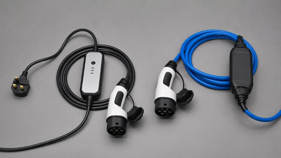
The quickest way to distinguish a Mode 2 portable EVSE cable from a Mode 3 fixed-installation cable is to look for the in-cable control box (ICCB) — that brick-shaped unit, usually 150–250 mm long, sitting somewhere along the cable between the plug and the vehicle connector. Mode 2 cables are designed for occasional use from a standard domestic or light-commercial socket, typically limited to 8–16A continuous, which puts you in the 1.8–3.7 kW range depending on voltage. They’re convenient, but the ICCB adds thermal mass and is a known failure point if the cable is coiled tightly during charging or left on a hot surface.
Mode 3 cables connect a vehicle directly to a fixed wall-box or charging station. No ICCB, no adapter brick. The communication and control circuitry lives in the station. These cables are rated up to 32A single-phase or 63A three-phase, covering roughly 7 kW up to 43 kW AC. The cable itself is correspondingly heavier — conductor cross-sections in this range typically run 4–10 mm² for the phase conductors, though high-current three-phase Mode 3 assemblies can use up to 16 mm² depending on the continuous current rating and derating for installation method.
Connector Formats and How to Tell Them Apart
The SAE J1772 Type 1 connector — dominant in North America and Japan — has five pins in a roughly oval housing, handles up to 240V AC single-phase, and uses a mechanical latch that clicks audibly when fully seated. It does not support three-phase AC natively. If you’re procuring cables for a North American fleet depot, every AC charge cable terminates here on the vehicle side.
IEC 62196 Type 2 is the European standard: seven pins, a rounder housing, and a flat locking face. It supports both single-phase and three-phase AC up to 400V, which is why a single cable design can serve everything from a 3.7 kW home charge to a 43 kW commercial fast-charger. Type 2 inlets also use an electromagnetic latch on the station side rather than a simple mechanical clip — relevant for procurement because it means the cable release depends on station power, not just the user’s grip.
CCS (Combined Charging System) connectors add a DC fast-charge pin block below the AC connector body. CCS Combo 1 pairs that DC block with a Type 1 AC top section; CCS Combo 2 pairs it with a Type 2 top. The physical size difference is immediately obvious — a CCS connector is noticeably taller than the AC-only equivalent, and the two large DC pins at the bottom are the definitive identifier. DC fast-charge cables for CCS are thick, often 35–50 mm² conductor cross-section, and liquid-cooled on higher-power stations above roughly 150 kW.
CHAdeMO uses a distinct round multi-pin format, larger in diameter than CCS, with a prominent trigger-style latch handle. It’s still relevant for older Nissan Leaf models, Mitsubishi Outlander PHEVs, and a portion of the Japanese domestic market fleet. If you’re managing a mixed-vehicle depot and see a round connector that doesn’t look like a hose fitting, it’s almost certainly CHAdeMO.
CCS Combo 2 supports both AC and DC charging through a single connectorTrue
The CCS Combo 2 design integrates the IEC 62196 Type 2 AC pins in the upper section with two additional DC pins in the lower section, allowing the same vehicle inlet to accept both AC Mode 3 and DC fast charging.
Reading the Rating Plate and Jacket Markings
Every compliant EV cable assembly carries a rating plate or embossed jacket markings. Minimum outdoor-rated cables carry IP44; anything exposed to pressure washing, heavy rain, or standing water at a fleet depot should be IP55 or better. The temperature rating matters more than people expect — a standard PVC-jacketed cable stiffens noticeably below 0°C and becomes genuinely difficult to handle and seat correctly below −10°C. For outdoor installations in northern climates, look specifically for TPE or rubber-compound jackets rated to −30°C or −40°C. That flexibility rating is usually printed directly on the jacket in a format like: −40°C / +90°C.
Maximum continuous current should be printed on the cable assembly, not just the station label. These sometimes disagree. The cable rating is the binding constraint.
Industrial IEC 60309 (CEE) Plugs in Fleet and Factory Environments
In factory charging bays, maintenance workshops, and fleet depots, you’ll commonly see IEC 60309 plugs — the industrial round connectors sometimes called CEE plugs. Color is the fast identification method: blue housings indicate 230V single-phase, red indicates 400V three-phase, and yellow (less common in EV contexts) indicates 110V center-tapped. The number of pins — 3, 4, or 5 — tells you grounding and neutral configuration. A red 5-pin CEE connector on a depot cable means three-phase, neutral, and ground, which is the standard configuration for high-power AC fleet charging infrastructure.
Procurement teams sourcing cables for mixed-use industrial facilities should verify that the CEE connector IP rating matches the installation environment. IP44 is the typical minimum for industrial outdoor use; IP67 is available for wash-down environments and worth the modest cost premium in food-processing or wet-floor facilities.
Seven Practical Tests You Can Perform Right Now Without Specialist Equipment
You don’t need a lab. Most of what follows requires a smartphone, a coin, and maybe a USB power meter you can order for a few dollars. Run through these in sequence — the early tests take seconds and often settle the question before you reach the later ones.
Test 1 — Shape Match Against a Scale Reference
Pull up the connector dimensional table from Section 2 and photograph your connector next to a standard coin (a US quarter is 24.3 mm across; a 1 euro coin is 23.25 mm). Compare proportions directly on your phone screen. USB-C is roughly 8.4 mm wide; USB-A is about 12 mm wide and noticeably rectangular. Micro-USB and Mini-USB are easy to confuse at a glance but differ clearly in pin count and housing profile once you have a reference beside them. This takes under a minute and rules out the most common misidentification.
Test 2 — Jacket Text Scan
Cheap cables often skip jacket printing entirely. That’s already a red flag. For cables that do have printing, switch your phone camera to macro mode (most mid-range phones from 2021 onward have a dedicated macro lens, or just tap to focus close) and photograph a 10–15 cm section of the jacket under decent light. Then cross-reference what you see against the certification guide in Section 3. You’re looking for AWG rating, voltage and current ratings, certification marks, and a manufacturer or batch identifier. Absent or blurry printing on a supposedly high-spec cable should make you suspicious.
Test 3 — Weight Check
A genuine 1 m USB-C cable rated at 100 W or higher typically weighs somewhere in the range of 28–45 g, depending on shielding, strain relief bulk, and connector housing material. A thin charge-only or counterfeit cable of the same length often comes in at 15–22 g. Use a kitchen scale or a postal scale if you have one. Heavier doesn’t automatically mean better, but significantly underweight for a claimed high-wattage cable is a consistent marker of undersized conductors.
Genuine high-wattage USB-C cables (100W+) weigh noticeably more than counterfeit equivalents of the same length.True
Higher power ratings require larger conductor cross-sections and more robust shielding, which directly increases cable mass. This is a well-documented physical relationship, not marketing.
Test 4 — Bend Stiffness
Hold the cable about 10 cm from one end and let it drape. A 20 AWG cable resists the bend and holds a loose arc; a 28 AWG cable flops freely. The difference is tactile and obvious once you’ve handled both. If a cable claiming to support 60 W or above bends like a headphone cable, the conductor cross-section probably doesn’t match the spec label.
Test 5 — Charging Speed Baseline
A USB-C inline power meter — the small passthrough dongles that display voltage, current, and wattage — costs roughly $8–20 and is the single most useful tool in this whole checklist. Plug your cable between a known USB PD charger and a device that supports USB PD, then watch the wattage reading as charging kicks in. A cable marketed as 100 W that negotiates only 18 W is either incompatible with PD or has an E-Marker chip issue. The meter won’t lie.
Test 6 — Heat Monitoring
After 10 minutes of charging at whatever load the previous test established, run your fingers along the cable, paying attention to the connector junction on both ends. Slight warmth is normal — resistive heating from even a good conductor is real. But if either junction feels hot to the touch, that’s a sign of inadequate conductor cross-section for the current being drawn. This is the test that catches “100 W” cables built with 28 AWG wire. Hot junctions under sustained load are where insulation degradation and, eventually, failures start.
Test 7 — Data Transfer Speed
Copy a file of roughly 1 GB (a large video works fine) from a USB storage device to your computer through the cable in question, and time it. USB 2.0 tops out around 480 Mbps theoretical, which translates to roughly 40–60 MB/s in real throughput. USB 3.2 Gen 2 should sustain somewhere above 900 MB/s on a capable host and drive. If a cable is sold as SuperSpeed and transfers at USB 2.0 rates, the internal wiring doesn’t match the connector. Some USB-C cables are wired for charging only and carry no high-speed data lines at all — that’s legitimate, but it needs to be disclosed on the jacket, and it means the cable can’t be repurposed for video output or fast file transfer regardless of the connector type.
Run all seven and you’ll have a confident picture of what you’re actually holding, usually within ten minutes.
How Cable Construction Quality Differs Between Budget, Mid-Range, and Industrial-Grade Products
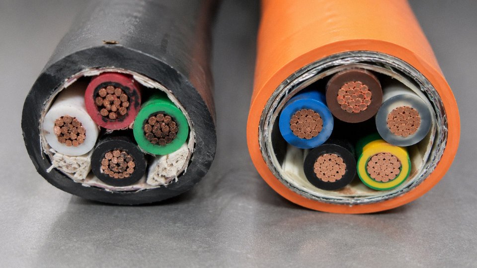
Pull apart a budget USB cable and a properly specified industrial one side by side, and the difference is immediately visible — sometimes embarrassingly so. The budget unit might have a conductor that looks like shiny copper but snaps under a light bend test. The industrial cable will have a cross-section that looks almost overcomplicated: multiple layers, a foil wrap, a braided shield, a drain wire, and conductors that are genuinely springy under flex. Understanding what each of those layers does is how you avoid buying the wrong thing twice.
Conductor Material: OFC vs. CCA
Copper-clad aluminum (CCA) conductors are common in low-cost cables because aluminum is roughly a third the weight and significantly cheaper than copper. The problem is resistivity. At the same nominal cross-section, CCA runs approximately 55–65% higher resistance than oxygen-free copper (OFC) — the exact figure depends on the cladding thickness ratio and the aluminum alloy used. In a short phone charger cable that rarely exceeds a few amps, that extra resistance might only cost you a degree or two of heating. Scale that up to a 5 A USB PD cable or a multi-conductor industrial assembly running continuous duty, and you get measurable voltage drop, thermal stress at the terminations, and a cable that meets its rated spec on paper but not in practice.
OFC isn’t just about conductivity, either. It work-hardens more slowly under repeated flex cycles, which matters enormously in applications where the cable moves constantly — a charging cable on a factory workstation, a USB tether on a robot arm, or a handheld scanner cable that gets coiled and uncoiled fifty times a day.
Stranding Architecture and Flex Life
Solid conductor cables — essentially a single wire per core — are cheap to produce and adequate for fixed installations. But flex life drops sharply. A solid 0.4 mm conductor might survive fewer than 1,000 full bend cycles before micro-cracking begins at stress points, usually right behind the connector or strain relief. A 7-strand construction using 0.12 mm individual wires at the same nominal cross-section can extend that to 10,000 cycles or beyond, with fine-stranded designs (19-strand, 49-strand) going further still for demanding applications. The penalty is manufacturing complexity — consistent lay length and uniform strand tension require real process control, not just more machines.
Insulation Materials
PVC is the baseline for most consumer cables: cheap, flame-retardant, adequate up to around 70°C. Polyethylene (PE) has lower dielectric loss and is preferred in high-frequency data cables where signal integrity matters more than cost. Cross-linked polyethylene (XLPE) pushes the continuous temperature rating to 90°C or 105°C depending on the crosslink density and the UL/IEC rating pursued — this is standard territory for EV charging cables and industrial power leads. TPE insulation is worth specifying when RoHS compliance is mandatory and flexibility in cold environments matters; it stays pliable down to temperatures where PVC turns stiff and brittle, which is a real issue for outdoor charging infrastructure in northern climates.
Shielding and the Drain Wire
Basic power-only cables skip shielding entirely — no real reason to add cost when EMI rejection isn’t required. Step up to USB, industrial data buses, or anything near variable-frequency drives, and shielding becomes non-negotiable. Aluminum foil (STP) provides good coverage against high-frequency radiated interference and is lightweight, but it’s fragile under flex and needs mechanical support. Braided copper shielding adds flex durability and better low-frequency attenuation, at higher cost and weight. Dual-shield construction — foil plus braid — is the right answer for sensitive medical instrumentation, servo drives, or any environment with aggressive electrical noise.
The drain wire is often overlooked in procurement specs, which is a mistake. Its job is to provide a continuous, low-impedance ground connection along the length of the shield. If the drain wire cross-section is undersized, ground impedance climbs, and noise rejection degrades precisely in the high-frequency bands where the shield is supposedly protecting you. In medical-grade cables, this isn’t academic — it directly affects device measurement accuracy and regulatory compliance.
Connector Contact Plating
Bare copper contacts oxidize quickly. Tin plating improves corrosion resistance and is entirely acceptable for lower-cycle applications. Nickel plating is harder and more durable, but nickel oxide is resistive, so contact resistance creeps upward over time in high-cycle connectors. Gold plating — typically in the 30 µin (0.76 µm) range for USB and similar connectors — prevents oxide formation and maintains stable contact resistance across tens of thousands of mating cycles. It’s the correct specification for connectors in industrial automation, medical devices, or anywhere that an intermittent connection causes a system fault rather than just an inconvenience.
Gold-plated contacts at 30 µin maintain stable contact resistance across high-cycle applications better than tin or nickel platingTrue
Gold's resistance to oxidation prevents the resistive oxide layers that develop on tin and nickel contacts over repeated mating cycles, which is well-documented in IEC 60512 connector testing standards.
Maintaining these construction tolerances consistently — conductor cross-section within tight limits, shielding coverage above 85%, insulation wall thickness uniform across millions of meters of output — requires manufacturing infrastructure that goes well beyond what a small cable operation can sustain. Jinda’s five production bases spanning 470,000 m² aren’t just capacity; they represent the process engineering and quality system depth needed to hold these specs across high-volume production runs without drift. That’s what separates a supplier you can audit from one that simply sends a compliant sample.
Frequently Asked Questions About Charging Cable Identification
Can I use a USB-C cable rated for 60W on a 100W charger safely?
Short answer: no, and the failure mode matters. A cable rated below 100W lacks an E-Marker chip — that small programmable IC embedded in a compliant 100W or 240W cable that tells the charger exactly what the cable can handle during the USB PD handshake. Without it, the charger either throttles down to a safe default (usually 60W or less, so you’re not getting what you paid for) or, on cheaper chargers with poor negotiation logic, it pushes current through conductors that genuinely aren’t sized for it. The cable jacket gets warm, then hot, then you have a problem. This isn’t theoretical. Charge-only cables shipped in budget accessory kits are frequently unlabeled 60W constructions, and people drop them onto 100W GaN chargers assuming “USB-C is USB-C.” It isn’t.
USB-C cables without an E-Marker chip cannot safely support charging above 60W under the USB PD specification.True
The USB Power Delivery specification requires an E-Marker chip for cables operating above 60W (3A at 20V). Without this chip, compliant chargers will cap output at 60W as a safety measure. Cables lacking the chip also tend to have lighter conductor cross-sections not rated for 5A continuous current.
How do I tell a USB 2.0 cable from a USB 3.0 cable when both connectors look identical?
On USB-A, the giveaway is right inside the port housing — USB 3.0 SuperSpeed ports and plug inserts use a blue-colored tongue, and the cable plug itself often carries the “SS” (SuperSpeed) logo molded near the base. That’s the quick visual. USB-C is trickier because the connector shell looks the same at 2.0, 3.2, and even Thunderbolt speeds. You can’t call it by eye. A proper protocol analyzer or a USB-C cable tester (the FNIRSI or similar bench tools run $30–80 depending on features) will read the cable’s internal wiring configuration and tell you exactly what’s there. A continuity check with a multimeter across all 24 pins will at least confirm whether the high-speed pairs are wired — time-consuming but doable in a pinch.
My cable charges my phone but won’t transfer data — what type is it?
Charge-only. These cables are wired with the VBUS (power) and GND conductors only; the D+ and D− data lines are simply absent. This is extremely common in cables bundled with wall adapters, particularly budget units from white-label suppliers. Manufacturers cut a few cents per unit by omitting two conductors, and most end-users never notice until they try to sync. You can confirm it with a multimeter set to continuity — probe the D+ pins on both ends and you’ll get nothing. Worth knowing before you spend an hour troubleshooting your PC’s device manager.
Is a frayed or kinked cable still safe to use?
No. Fraying at the strain relief zone exposes the inner conductors to intermittent contact, flexing, and eventually short-circuit conditions. At 5A — which is normal for a 100W USB PD cable — that’s a genuine fire risk, not a mild inconvenience. A kink that has set into a permanent bend has likely compromised the insulation integrity at that point even if you can’t see bare copper yet. Throw it out. The replacement costs less than the repair bill, let alone what a wire fire costs.
What does the E-Marker label mean on a USB-C cable?
The E-Marker is a small chip, typically compliant with the USB PD specification, embedded inside one of the cable’s plugs. During the power delivery handshake, the charger reads this chip to learn the cable’s rated current and voltage ceiling. A cable with an E-Marker rated at 5A/20V enables 100W charging; the newer USB PD 3.1 spec pushes that to 240W with appropriately rated chips and heavier conductors. If the cable has no E-Marker, the handshake defaults to the conservative 60W cap. When procuring in bulk, ask suppliers specifically for the E-Marker rating in the product datasheet — not just “supports 100W” written on the packaging, which is often aspirational.
Can I identify my EV charging cable by its color alone?
Orange jackets are a common convention for EV high-voltage wiring, but it’s a convention, not a binding standard in most markets. In practice, some manufacturers use black or grey jackets on perfectly legitimate SAE J1772 or IEC 62196 cables. Conductor cross-sections in EV charging cables run from roughly 1.5 mm² on a slow Level 1 circuit up to 35–50 mm² on high-power DC fast chargers, and that range alone tells you more about the cable’s rating than color does. Always verify by connector shape, the rating plate near the handle or inline control box, and pin count. Color is a quick first filter, nothing more.
How long should a quality charging cable last under daily use?
A well-built cable — proper strain relief at both terminations, high strand-count conductors (finely stranded copper flexes without work-hardening), decent TPE or braided outer jacket — should handle somewhere in the range of 10,000 to 15,000 flex cycles before conductor fatigue becomes a real concern. In practice, daily plug-unplug on a bedside cable works out to several years of reliable service. Budget cables with stiff PVC jackets and coarsely stranded conductors often crack at the strain relief within 6–12 months, sometimes sooner in cold environments where PVC stiffens further. The failure usually starts at the plug end, where the bend radius is tightest and the strain relief is shortest. If you’ve replaced the same cable three times in two years, the cable construction — not bad luck — is the variable worth changing.
Procurement Checklist for Bulk Cable Orders: What to Specify to Avoid Costly Substitutions
Sourcing cables at volume is where the technical knowledge you’ve built throughout this article either protects you or fails you. A buyer who can identify a USB-C Gen 2 cable by sight still gets burned if the purchase order leaves room for “equivalent substitution.” That clause is where margin-squeezed suppliers swap oxygen-free copper conductors for copper-clad aluminum, downgrade insulation temperature ratings, or ship unshielded cables against a spec that called for foil-plus-braid. The field failures that follow — overheating connectors, intermittent data loss, cables that fail incoming inspection — are entirely predictable in hindsight.
The Seven Fields Every Cable PO Must Lock Down
Leave any of these undefined and you’ve handed the supplier discretion you probably didn’t intend to give.
| Specification Field | What to State Explicitly | Why Vagueness Costs You |
|---|---|---|
| Connector type and revision | e.g., USB Type-C, USB 2.0 rev, with 24-pin full-wiring | A “USB-C cable” legally includes 2-wire charge-only variants |
| Conductor cross-section | mm² per conductor, not AWG alone | AWG tolerances allow meaningful variation; mm² is unambiguous |
| Conductor material | OFC (oxygen-free copper), specify purity if critical | CCA is commonly offered as “equivalent”; it is not |
| Insulation material and temp rating | e.g., PVC 75 °C, LSZH 90 °C, silicone 150 °C | Thermal class determines safe ampacity in bundled or conduit runs |
| Shielding type | None / foil / braid / foil+braid; coverage % for braid | Omitting this opens the door to unshielded substitution |
| Jacket material | PVC, TPE, TPU, LSZH — and Shore hardness if flex life matters | TPE and PVC feel similar; long-term flex fatigue is very different |
| Required certification marks | UL listing number, CE, RoHS, IEC 62368-1, etc. | “Certified-looking” logos on jacket print are not the same as a verifiable listing |
For EV or industrial cables rated above roughly 32 A, add conductor cross-section for the pilot and ground wires separately — those are frequently undersized in budget product.
The Equivalent-Substitution Problem
Copper-clad aluminum (CCA) conductors are sometimes supplied as an equivalent substitute for oxygen-free copper (OFC) in cable orders where conductor material is not explicitly specified.True
CCA has significantly lower conductivity than OFC (roughly 61% IACS vs. OFC's ~101% IACS), higher resistive losses at elevated current, and different mechanical properties that affect crimp termination reliability. The substitution is common in price-competitive markets and is a documented source of overheating and connector failures in charging applications.
Write “conductor material: OFC, CCA not acceptable as equivalent” in plain text on the PO. Contract language that says “or equivalent” almost always means “or cheaper.”
Audit Documents Worth Requesting Before Payment
Ask for the UL certification number and verify it yourself on UL Product iQ — takes about two minutes and immediately separates legitimate listings from printed logos. For cables used in battery-connected or portable charging applications, IEC 62368-1 and IEC 62133 test reports from an accredited third-party lab (SGS, TÜV, Intertek) are the baseline. Factory audit reports from the past 12 months are reasonable to request on orders above roughly 10,000 units; many established manufacturers maintain these routinely.
Packaging and Logistics Specifications
For international shipments, specify reel length (typically 100 m, 200 m, or 500 m per reel depending on cable diameter), inner carton count, outer carton dimensions, and gross weight per carton. This isn’t bureaucratic — it directly affects palletization efficiency and customs declaration accuracy. Mislabeled reel lengths cause receiving errors that delay production line restocking.
MOQ Realities
Standard catalog cables generally start around 500–1,000 meters per SKU, depending on the manufacturer and connector type. Custom jacket colors, custom overmold branding, or non-standard labeling typically push the minimum to somewhere in the 5,000-meter range, sometimes higher for specialty compounds. Factor that threshold into your SKU consolidation strategy early, not after sampling.
Working With a Vertically Integrated Supplier
The practical advantage of sourcing from a manufacturer with in-house R&D, production, and technical support — rather than a trading company reselling third-party product — is traceability. When a shipment fails incoming inspection, you need someone who can pull conductor test records and extrusion batch data, not someone who has to relay your question to an unknown factory. Jinda’s structure, covering the full chain from compound development through after-sales support across 50+ countries, means specification changes and non-conformance investigations have a single accountable point of contact. For long-term procurement relationships, that matters more than a slightly lower unit price from a less integrated supplier.