Specifying the wrong cable for an application is one of those mistakes that rarely announces itself at the purchasing stage — it shows up later, as a tripped breaker during peak production, insulation that cracks after one winter outdoors, or a motor feed that runs warm enough to accelerate aging by years. The financial hit is rarely just the cable itself; it’s the unplanned downtime, the electrician hours, and sometimes a damaged load at the end of the run.
A power cable is compatible when its voltage rating meets or exceeds the system’s nominal voltage (per IEC 60502 or equivalent), its conductor cross-section carries the design load current without exceeding the insulation’s temperature class, its jacket and insulation materials suit the installation environment, and it complies with any local or project-specific approval requirements. All four conditions must be satisfied simultaneously — meeting three out of four still produces an incompatible cable.
What makes this genuinely tricky is that the four criteria interact. A cable that’s correctly sized for current can still fail early if its 70°C PVC insulation is installed in a duct where ambient plus self-heating pushes conductor temperature past that limit — something that’s easy to miss when the nameplate rating looks fine on paper. The sections below work through each compatibility dimension the way you’d actually check it on a real project, from reading a cable’s drum label to cross-referencing installation conditions most datasheets don’t warn you about.
Decoding Voltage Ratings: Matching Your Cable’s U0/U Designation to Your System
The single most common specification error I see on international cable orders — and it shows up more than people admit — is a mismatch between the system voltage and what the cable’s voltage designation actually means. A procurement manager sees “1 kV cable” on a datasheet and assumes it covers a 1 kV system. It might. It might not. The notation matters enormously.
What U0, U, and Um Actually Mean
IEC standards use a three-part designation written as U0/U (kV), sometimes with Um stated separately. These are not interchangeable numbers:
U0 is the rated voltage from conductor to earth (or to the metallic screen). This is the number that governs insulation thickness. U is the rated voltage between any two phase conductors. Um is the maximum system voltage the cable can withstand continuously — not a test voltage, but the upper bound of normal operating voltage including steady-state supply variations.
A cable marked 0.6/1 kV means 600 V conductor-to-earth, 1,000 V phase-to-phase. For a standard 400 V three-phase system, U0 works out to roughly 231 V — well within the 600 V rating. That’s why 0.6/1 kV is the workhorse designation for most low-voltage industrial and commercial installations globally.
System Voltage to Cable Class: A Practical Cross-Reference
Use this as a starting sanity check when reviewing a specification sheet or purchase order. The “correct cable class” column reflects standard engineering practice, not just the theoretical minimum.
| Nominal System Voltage | Typical Application | Correct Cable Voltage Class | Relevant IEC Standard |
|---|---|---|---|
| 230/400 V | Commercial, industrial LV | 0.6/1 kV | IEC 60502-1 |
| 690 V (motor drives) | Industrial MCC, VFD output | 0.6/1 kV | IEC 60502-1 |
| 6/10 kV | MV distribution, substations | 6/10 kV | IEC 60502-2 |
| 20/35 kV | Regional distribution networks | 18/30 kV | IEC 60502-2 |
| 66/110 kV | Transmission, large industrial tie-ins | 64/110 kV | IEC 60840 |
Why “Rated at System Voltage” Is Not Enough
Specifying a cable rated exactly at your nominal system voltage leaves essentially no headroom. In practice, harmonic distortion from variable-frequency drives, capacitor bank switching transients, and routine supply fluctuations can push instantaneous voltage 10–15% above nominal for brief but repeated intervals. Over months and years, that stress degrades insulation — particularly at terminations and joints where field enhancement already occurs.
Standard engineering practice is to specify one voltage class higher than your nominal system voltage where the classes are closely spaced, or at minimum to verify that the cable’s Um value exceeds your system’s highest expected voltage. This is not conservative over-engineering; it’s just how competent cable specifiers have always worked.
A cable rated exactly at nominal system voltage provides no margin for transient overvoltages and will degrade faster in systems with harmonic distortion or frequent switching events.True
IEC 60502 and IEC 60840 both define Um as the maximum continuous system voltage, and cable insulation design accounts for this ceiling. Systems with VFDs, power factor correction banks, or long feeder runs routinely experience transients that exceed nominal voltage by 10–15%, which accelerates partial discharge activity and insulation aging in cables with no Um headroom.
AC vs. DC: A Rating You Cannot Directly Transfer
This one catches people out, especially on renewable energy and battery storage projects. A cable rated 1 kV AC cannot simply be reused on a 1 kV DC circuit. DC voltage stresses insulation differently — there’s no zero-crossing, so space charge accumulates within the dielectric over time, distorting the electric field distribution in ways that AC cycling partially mitigates. The practical rule of thumb is that a DC application requires a cable rated at roughly 1.5× the equivalent AC voltage. So a 1 kV DC system typically calls for a cable with an AC rating in the range of 1.5–1.8 kV, or a cable specifically designed and tested for DC service. Check the test certificate; “DC-rated” should appear explicitly.
Worked Example: 690 V Motor Drive, Cable Marked 0.6/1 kV
A project engineer receives a shipment for a new compressor house. The motor drives run at 690 V, and the cables are marked 0.6/1 kV. Is this acceptable?
Yes — with checks. The phase-to-phase voltage (690 V) is below the U rating of 1,000 V. The conductor-to-earth voltage in a solidly earthed 690 V system is roughly 398 V, well below the U0 of 600 V. The Um for standard 0.6/1 kV cables is typically 1.2 kV, which covers normal transients on a 690 V bus.
What to verify on the test certificate: conductor resistance per IEC 60228, insulation resistance, and high-voltage withstand test results. For XLPE-insulated cables, partial discharge measurement is the more sensitive indicator of insulation quality — Jinda’s medium-voltage XLPE cables are manufactured and tested to IEC 60502-2, with routine partial discharge tests conducted at 2U0, which means a 6/10 kV cable is tested at 12 kV phase-to-earth. That test result is something a buyer can actually point to.
One thing to confirm on any 690 V VFD-fed installation specifically: check whether the cable insulation is rated for the steeper voltage rise times (dV/dt) that pulse-width-modulated drives produce. Standard 0.6/1 kV PVC cables usually handle it, but if the drive has long cable runs — say, over 50–80 m depending on the drive brand and switching frequency — a cable with XLPE or EPR insulation is a safer choice.
Current-Carrying Capacity and Conductor Sizing: Reading Ampacity Tables Without Making Dangerous Assumptions
Ampacity — the maximum continuous current a cable can carry without exceeding its insulation’s rated temperature — is determined by a heat balance, not a single material property. Three things govern it: the I²R heat generated in the conductor itself (which rises with resistivity and the square of current, so doubling current quadruples heat generation), the thermal resistance of the insulation and surrounding materials slowing that heat’s escape, and the ambient heat dissipation pathway — whether the cable is hanging in moving air, buried in dry sand, or packed into a conduit with five other cables. Change any one of those three conditions and your table value becomes unreliable.
Baseline Ampacity Reference — IEC 60364-5-52 Standard Conditions
The table below applies to copper and aluminum conductors with XLPE insulation, single circuit, in free air, at 30°C ambient. These are starting-point numbers. Real installations almost never match all three conditions simultaneously.
| Cross-Section | Copper (A) | Aluminum (A) |
|---|---|---|
| 16 mm² | 100–110 | 78–86 |
| 35 mm² | 150–165 | 117–128 |
| 70 mm² | 205–225 | 160–175 |
| 95 mm² | 245–265 | 190–206 |
| 150 mm² | 305–335 | 238–260 |
| 240 mm² | 390–430 | 304–335 |
| 300 mm² | 440–490 | 343–382 |
Ranges reflect variation across conductor stranding, jacket construction, and installation method sub-categories within the standard. Manufacturers’ certified datasheets take precedence over generic tables — always cross-check.
The Four Derating Factors Engineers Routinely Underestimate
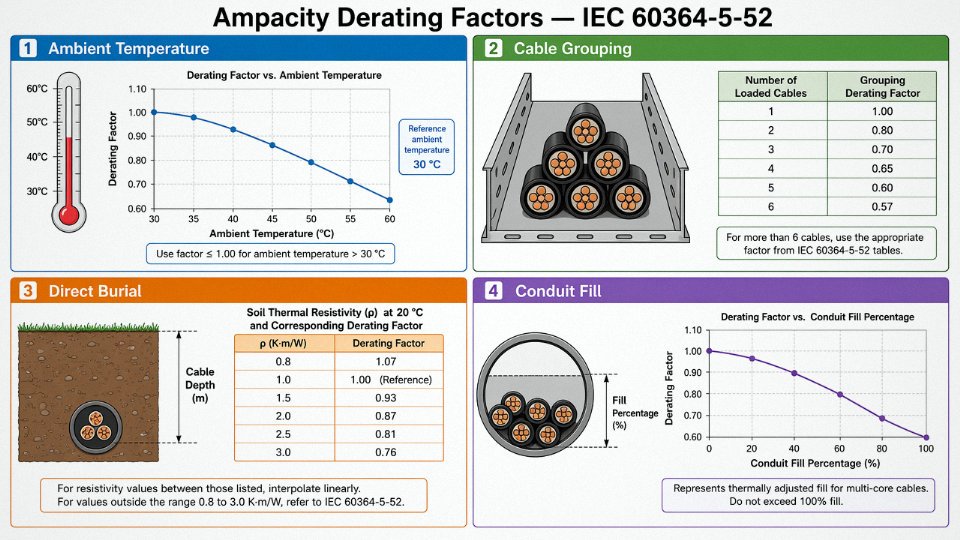
Elevated ambient temperature is the most straightforward. Every 10°C rise above 30°C reduces XLPE cable ampacity roughly 5–8%, depending on how close the operating point sits to the thermal limit. In a Middle Eastern substation yard running 50°C summers, you can easily be looking at a 15–20% capacity reduction before you’ve accounted for anything else.
Grouping cables in a bundle is where I see the worst assumptions made. A single cable in free air has the full table rating. Six loaded cables touching each other in a tray drop to roughly 57% of that single-cable figure per IEC grouping factors. Engineers sometimes check the ampacity table, see it’s “fine,” and then route twelve cables through the same conduit without recalculating. That’s how you get insulation that looks intact externally but has been thermally degraded for two years.
Direct burial introduces soil thermal resistivity — a value that varies wildly between dry sandy soil (around 2.5–3.0 K·m/W) and moist clay (0.8–1.2 K·m/W). Dry conditions, which is also when load tends to peak seasonally, give the worst derating. This is worth checking against local soil data, not assuming.
Conduit fill ratio matters most in tightly packed electrical rooms and commercial buildings. As fill increases above about 40%, heat removal degrades noticeably.
A Real Derating Calculation, Step by Step
Take a 95 mm² XLPE copper cable. Free-air rating from the table: roughly 250 A. Now bury it in soil with thermal resistivity of 2.5 K·m/W (dry, summer conditions), with two other fully loaded cables in the same trench, at an ambient soil temperature of 40°C.
Derating for soil resistivity and burial method: apply approximately 0.89. Derating for 40°C ambient on XLPE (rated 90°C): approximately 0.94. Derating for three cables in the trench: approximately 0.85.
250 A × 0.89 × 0.94 × 0.85 ≈ 178 A
That’s a 29% reduction from the table value. If you designed the circuit assuming 250 A capacity, you’ve built a thermal failure in.
A 95 mm² XLPE copper cable rated ~250 A in free air can derate to approximately 178 A when buried in dry soil at 40°C alongside two other loaded cables.True
Applying IEC 60364-5-52 correction factors for soil thermal resistivity 2.5 K·m/W, elevated ambient temperature, and cable grouping yields compound derating to roughly 71% of the free-air rating, consistent with the standard's tabulated factors.
Aluminum vs. Copper: When the Economics Actually Work
Aluminum at the same cross-section carries roughly 60% of copper’s current — that’s not a rounding difference, it’s a full conductor-size step up. A 95 mm² aluminum cable is closer in capacity to a 70 mm² copper cable than to its copper equivalent. However, aluminum weighs about 50% less and typically costs 30–40% less per meter at comparable conductor sizes, which matters enormously on long overhead runs or large industrial projects where you’re buying kilometers. For fixed underground infrastructure with stable termination points and skilled jointing crews, aluminum is often the economically correct choice. For frequent-termination environments, tight conduit runs, or marine applications where galvanic corrosion risk at connections is harder to control, copper remains the practical default.
Voltage Drop Can Force a Larger Conductor Than Ampacity Alone
On long cable runs — say, a 200-meter feed to a remote motor — voltage drop often drives conductor selection before thermal ampacity does. IEC 60364-5-52 guidance targets below 3% drop for branch circuits and below 5% total for feeders. At 150 meters or more, even a lightly loaded circuit on small conductor cross-sections can breach those limits, pushing you to upsize purely for voltage quality rather than heat.
Jinda’s technical datasheets cover conductor sizes from 0.5 mm² control cable conductors through to 1000 mm² power cable conductors, with ampacity tables broken down by installation method — free air, buried, in conduit, in trunking. That level of specificity in the documentation is what makes a real compatibility check possible, rather than relying on generic reference tables that may not match your installation geometry at all.
Insulation and Jacket Material Compatibility: Matching Chemistry to the Operating Environment
Material selection is where a lot of procurement decisions go quietly wrong. An engineer specifies the right voltage rating, sizes the conductor correctly, then picks “standard PVC” because it’s familiar and cheap — and six months later the cable is cracking in a cold-room application, swelling in an oil mist environment, or failing a smoke toxicity inspection on a tunnel project. The insulation and jacket materials are not cosmetic. They define the cable’s chemical identity inside a specific environment.
The Four Main Insulation Materials and Where They Actually Belong
PVC insulation handles the range of roughly –15°C to 70°C and dominates general-purpose building wiring, control panels, and dry industrial environments because it’s inexpensive and easy to terminate. Below about –10°C it starts to stiffen noticeably, and in cold-storage facilities or outdoor Nordic installations that rigidity causes cracking at bends — something you won’t see coming until the insulation is already compromised.
XLPE (cross-linked polyethylene) runs –40°C to 90°C continuously and has significantly lower dielectric losses than PVC at medium voltage. Above roughly 6 kV, that loss differential stops being a theoretical footnote and becomes a real efficiency and heat-dissipation issue. This is why XLPE is essentially the only serious option for medium-voltage feeders — it’s not just about temperature rating, it’s about not wasting energy as heat inside the insulation wall itself.
Standard PVC insulation is suitable for medium-voltage cables above 6 kVFalse
PVC's dielectric losses become thermally and energetically unacceptable at medium voltage. IEC 60502 applications above 6 kV standardly specify XLPE or EPR insulation, not PVC.
EPR (ethylene propylene rubber) covers –50°C to 90°C and stays flexible even at extreme cold — that’s why it’s the go-to insulation in mining trailing cables, offshore platform power leads, and shipboard wiring where the cable gets coiled, dragged, and exposed to seawater spray. It handles physical abuse better than XLPE in dynamic applications. It costs more, and in a static installation you rarely need it, but try pulling a stiff XLPE cable across a North Sea drill floor in January and you’ll understand quickly why EPR exists.
Silicone rubber runs from –60°C up to roughly 180°C and is the material for fire-survival circuits — emergency lighting feeds, smoke exhaust fan supplies, fire pump cables — where the cable must continue functioning during and after a fire event. It’s not a general-purpose upgrade. The cost is substantially higher, the mechanical toughness is lower than PVC in abrasion-prone routes, and it’s specified only where fire performance standards explicitly demand it.
Outer Jacket Selection: The Environment Dictates the Sheath
The jacket takes the physical punishment: UV, moisture, mechanical contact, chemical splashes. General-purpose PVC jacket works in most sheltered industrial locations. LSZH (low-smoke zero-halogen) sheathing is mandatory in tunnels, metro stations, data centers, and any confined space where burning cable would otherwise fill the escape route with dense toxic smoke. Under EN 50575, European public building projects increasingly require a minimum B2ca fire classification, which in practice means LSZH construction. That’s a regulatory driver with real procurement consequences — specifying a standard PVC-jacketed cable on a European infrastructure tender can get the whole cable supply rejected at inspection.
Polyurethane jacket is the right answer for trailing cables on cranes, drag chains, and mobile machinery because its abrasion resistance is far above anything PVC can offer at comparable wall thickness. HDPE jacket handles direct-burial in aggressive or wet soils — the moisture impermeability and chemical inertness matter over a 20–30 year service life in a way that PVC simply can’t match.
Chemical Compatibility Is Non-Negotiable in Process Environments
Standard PVC sheathing will swell, soften, and lose tensile strength when immersed in mineral oil — sometimes within a matter of weeks under continuous exposure. In machine tool cable trays, hydraulic press areas, and petrochemical plants, oil-resistant sheathing (nitrile rubber compounds or specifically formulated oil-resistant PVC) is not optional. The failure mode is gradual: the jacket softens, loses its mechanical protection role, and the insulation beneath becomes exposed to contamination and physical damage before anyone notices.
UV degradation is a separate chemical mechanism that catches people off-guard. Natural or light-colored PVC degrades in outdoor solar exposure, often showing surface cracking within two to five years depending on UV index and temperature cycling. Standard black HDPE or properly UV-stabilized black PVC maintains its properties for 20 years or more. If the cable runs on an outdoor tray or rack with no conduit protection, verify the UV stabilization specification, not just the material type.
Quick-Reference: Environment to Material Combinations
| Operating Environment | Recommended Insulation | Recommended Jacket | Key Reason |
|---|---|---|---|
| Marine / offshore | EPR | CSP or LSZH | Flexibility, seawater resistance, fire safety |
| Direct buried, aggressive soil | XLPE | HDPE + armour | Moisture impermeability, mechanical protection |
| Food processing (wash-down) | XLPE | Polyurethane or food-grade PVC | Chemical resistance, abrasion, cleanability |
| Data center raised floor | XLPE or PVC | LSZH | Smoke toxicity, fire classification |
| Outdoor cable tray | XLPE | UV-stabilized PVC or HDPE | UV and thermal cycling resistance |
| Explosive atmosphere (ATEX/IECEx) | XLPE | LSZH or nitrile rubber | Anti-static, fire performance, certification |
| Machine tool / oil-immersion risk | XLPE | Oil-resistant PVC or nitrile | Resistance to mineral oil swelling |
| Cold climate (below –25°C) | EPR | PUR or EPR sheath | Flexibility at low temperature |
The table is a starting point, not a specification. Actual material suitability depends on concentration levels for chemical exposure, exact temperature cycling profiles, and whatever local fire code or industry certification applies to the installation. When in doubt on a demanding application, ask the cable manufacturer for immersion test data or a material compatibility certificate against the specific chemicals present — reputable manufacturers can provide it.
Screening, Armoring, and Mechanical Protection: When the Cable’s Structure Must Match the Installation Method
Most procurement errors I’ve seen in this area aren’t voltage mistakes or even sizing mistakes — they’re structural ones. Someone specifies a cable for an underground run and forgets to ask whether it’s going into a duct or direct-buried. Someone orders screened cable for a VFD installation and then leaves the screen floating at one end. The cable looks right on paper and fails in the field.
The metallic layers in a power or instrumentation cable serve three distinct functions, and conflating them is where things go wrong.
Electrostatic Screens: EMI Control in Control and Instrumentation Cables
A copper tape or braid screen around signal and control pairs exists to block electrostatic interference. It does nothing useful if it isn’t grounded. In instrumentation circuits — 4–20 mA loops, thermocouple extensions, HART — the standard practice is to ground the screen at one end only, typically the control-room end, to avoid creating a ground loop that introduces the noise you were trying to eliminate. In high-EMI environments like VFD-heavy motor control centers, you may need an overall braid plus individual pair screens, grounded at both ends with a continuous low-impedance path. A shield grounded through a long, thin wire defeats much of its own purpose; the grounding conductor should be short and direct.
A floating (ungrounded) cable screen provides no EMI protection and can accumulate charge to hazardous voltage levels in high-interference environments.True
An ungrounded screen cannot form the return path needed to divert induced currents to earth. In high-voltage proximity, capacitive coupling can raise the screen to shock-risk potentials relative to ground.
Concentric Neutrals: A Different Animal Entirely
Single-core medium-voltage cables — 6 kV to 36 kV range, usually — often carry a layer of helically applied copper wires that look superficially like armor but aren’t. This is the concentric neutral, and its job is to carry fault return current and maintain the radial electric field symmetry that the insulation screen depends on. Treat this as a current-carrying conductor in your installation design, size the neutral for the expected fault level, and ensure it’s properly bonded at terminations. Confusing the concentric neutral with mechanical armor and skipping a separate earth conductor is a real mistake in MV distribution work.
Armor Selection: Steel, Aluminum, Tape, or None
Steel wire armor (SWA) is the workhorse for direct burial and cable tray. It resists rodent attack, incidental mechanical damage during installation, and tensile stress on long trench pulls. For three-core and multicore AC cables, the steel losses are manageable. For single-core AC cables carrying substantial current, SWA creates a closed magnetic circuit around a single-phase conductor, and eddy-current heating in the steel can be significant enough to require derating by 10–20% depending on cable size and load current. Aluminum wire armor (AWA) breaks that problem: aluminum’s lower permeability avoids the eddy-current trap while still providing reasonable mechanical protection.
Steel tape armor (STA) and double steel tape armor (DSTA) address a different requirement — radial crush resistance rather than tensile strength. A smaller cable run under a roadway in conduit where pulling tension is low but ground movement or compaction loading is the concern suits DSTA better than SWA.
Flexible applications — cable chains on CNC machines, festoon systems, robotic arms — need an entirely different construction philosophy. Standard SWA is rigid enough that repeated flex cycles crack the wires within a few thousand cycles, causing intermittent faults that are genuinely maddening to trace. These installations require fine-wire braided screen or spiral-wound armor, stranded (not solid-segmental) conductors, and a flexible compound jacket — typically PUR rather than PVC. Specifying flex-cycle life and bend radius to your supplier at the RFQ stage saves real grief later.
Matching Construction to Installation Method
| Installation Scenario | Recommended Construction |
|---|---|
| Direct burial, no duct | SWA + HDPE or PVC oversheath; DSTA for smaller cables in unstable soil |
| Underground duct or conduit | Unarmored XLPE acceptable; light SWA if pulling tension is high |
| Cable tray, indoor | Unarmored XLPE/LSZH or SWA where mechanical damage risk exists |
| Single-core MV cable, any route | AWA (not SWA) to control eddy-current losses |
| Continuous flex (cable chain, festoon) | Fine-wire braid or spiral armor; stranded conductors; PUR outer jacket |
| Submersible pump drop cable | Flat parallel construction with polypropylene fillers; water-resistant insulation |
| Overhead self-supporting | Aerial bundled conductor with integral messenger wire; no conventional armor needed |
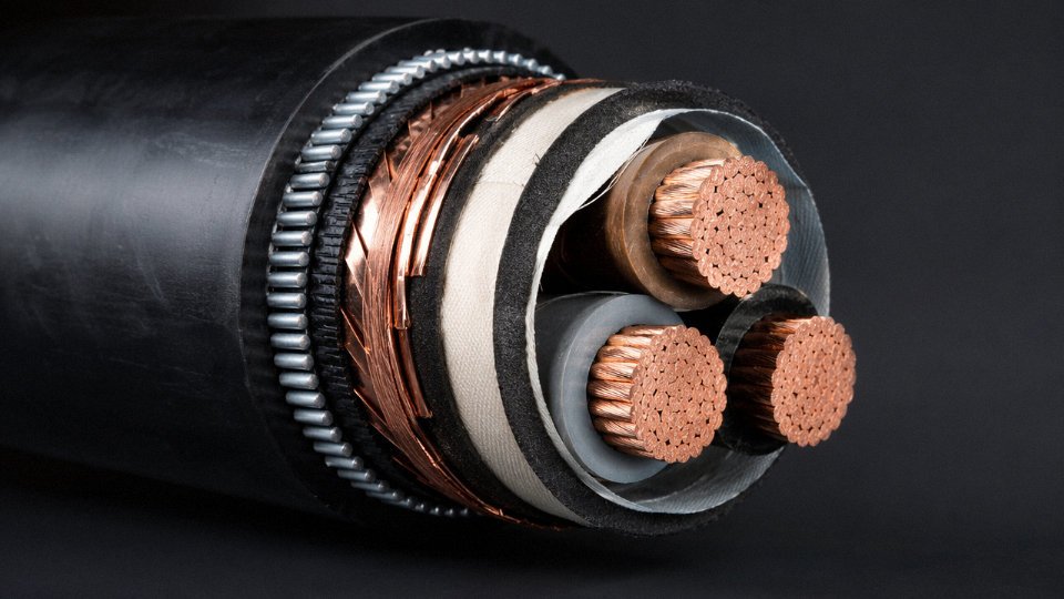
One practical note: oversheath color coding for armored cables varies by standard and by country. Black HDPE oversheath is common for direct-burial cables in IEC markets; yellow is sometimes used to signal gas-service proximity. Don’t assume oversheath color carries a universal meaning across procurement regions — verify the marking convention with your supplier against the applicable installation code.
Regulatory Certifications and International Standards: What the Marks on the Cable Drum Actually Mean
Walk into any port-of-entry inspection shed and you’ll find cable drums sitting in customs hold because someone conflated “manufactured to IEC 60502” with “certified to IEC 60502.” Those are not the same thing, and the difference can stall a project for weeks.
Standards vs. Certification Marks — A Distinction That Actually Matters
A design standard like IEC 60502, IEC 60227, IEC 60245, BS 5467, or AS/NZS 5000 defines the construction requirements, test methods, and performance thresholds a cable must meet. A certification mark — CE, KEMA, UL Listed, CSA, SAA — means an accredited third party has independently verified that a production sample actually meets those requirements and that the manufacturer’s quality system is under ongoing surveillance. A cable can be built to IEC 60502 dimensions and materials without ever having been tested by anyone outside the factory. Whether that matters depends entirely on what your project authority or end-client specifies in their procurement documents. Many do not specify it clearly, which is where procurement managers get burned.
Market Access Requirements by Region
The requirements vary enough that a cable perfectly legal in one market can be rejected outright in another.
| Destination Market | Required Standard / Regulation | Certification / Mark Needed |
|---|---|---|
| European Union | EN 50575 (CPR) + applicable IEC/HD | CE marking, fire class declaration of performance |
| United States | UL 44 (thermoset), UL 83 (thermoplastic) | UL Listed mark; NEC article compliance |
| Canada | CSA C22.2 No. 0.3 / No. 38 etc. | CSA mark |
| Australia / New Zealand | AS/NZS 5000 series | SAA mark (now RCM) |
| Saudi Arabia | SASO technical regulations | SASO conformity certificate |
| Nigeria | SON regulatory framework | SONCAP certificate of conformity |
The EU’s Construction Products Regulation is worth pausing on. Since EN 50575 came into force, cables installed as permanent parts of a building structure must carry a declared fire performance class — Eca being the minimum, through Dca, Cca, Bca, up to Aca. Shipping a cable without a valid Declaration of Performance for the correct class will get it rejected on a building project in Germany or France regardless of how well the cable is actually built.
What a Legitimate Test Certificate Must Contain
A test report from an ISO/IEC 17025-accredited laboratory should show the laboratory’s name and its accreditation body registration number — verify that number directly on the accreditation body’s public registry, because it takes about 90 seconds and most buyers never do it. The report should reference the specific standard clause by clause, list measured values for conductor DC resistance, insulation resistance, and high-voltage withstand, and carry a unique certificate number that the issuing lab can confirm if you call or email them. If a supplier hands you a certificate that shows only pass/fail without measured values, that is not a test report. That is a declaration dressed up to look like one.
A cable marked 'to IEC 60502' has been independently certified by a third-party laboratory.False
Manufactured 'to' a standard means the cable was designed against those requirements. Independent third-party certification requires a separate accreditation process and ongoing factory audits. Always ask for the certification body's confirmation, not just the printed mark.
The Fraud Vectors That Actually Show Up in Global Procurement
Certification fraud in cable supply is not hypothetical — it is routine enough that experienced procurement teams treat every certificate as suspect until verified. The most common patterns: photocopied certificates with dates or product codes digitally altered, certificates legitimately issued for a 16 mm² XLPE product applied to an order of 50 mm² PVC product, and third-party marks screen-printed on drum labels without authorization from the certification body. The fix is straightforward but requires discipline. Cross-check the drum print character by character against the certificate — conductor cross-section, voltage designation, insulation material, number of cores, standard reference. Then contact the issuing body directly, not through the supplier.
Due-Diligence Checklist for International Cable Procurement
Before approving a supplier or releasing a purchase order for any internationally shipped cable:
- Request the full technical data sheet for the exact product code, not a generic family brochure
- Ask for a sample test certificate for that specific product code, with accreditation number visible
- Verify the certificate on the accreditation body’s public registry — ILAC, UKAS, DAkkS, NATA, depending on the lab’s home country
- Check drum print against certificate specifications line by line, including lot or batch reference where applicable
- Confirm the certification mark authorization with the issuing body if the order is high-value or the mark is required for project authority approval
Jinda’s export documentation package is built around exactly this process — test reports referencing specific IEC, BS, and AS/NZS clauses, material certificates, and third-party inspection records structured to support customs clearance and project authority submission. When a project requires AS/NZS 5000 compliance for an Australian site or CPR fire class documentation for a European contractor, the paperwork needs to arrive complete the first time. One missing document at the point of customs inspection can hold an entire cable consignment, and in practice, that delay rarely costs less than the original cable value when you account for project penalties and re-procurement logistics.
Step-by-Step Field Compatibility Verification Before You Energize
Design drawings and purchase orders tell you what should be on site. A field verification protocol tells you what is. These are not always the same thing, and the gap between them is where commissioning failures live.
Work through the following steps in sequence. Skipping one to save an afternoon has a habit of costing a week.
Step 1 — Visual Drum and Reel Inspection
Before anything touches a meter or a megohmmeter, read the drum label. It should show the voltage designation (U₀/U in kV), conductor cross-section in mm², insulation type, standard number (IEC 60502-1, for instance), length, drum serial number, and the manufacturer’s name. Check every one of those fields against your purchase order, not just the cross-section. A 4×95 mm² XLPE/SWA cable for a 6.6 kV system is not interchangeable with the same size rated 0.6/1 kV, even if it looks identical in a cable tray.
Photograph the drum label and tie that photograph to the drum serial number in your commissioning record. If a fault surfaces eighteen months later, that image is worth considerably more than a handwritten note.
Step 2 — Physical Dimensional Verification
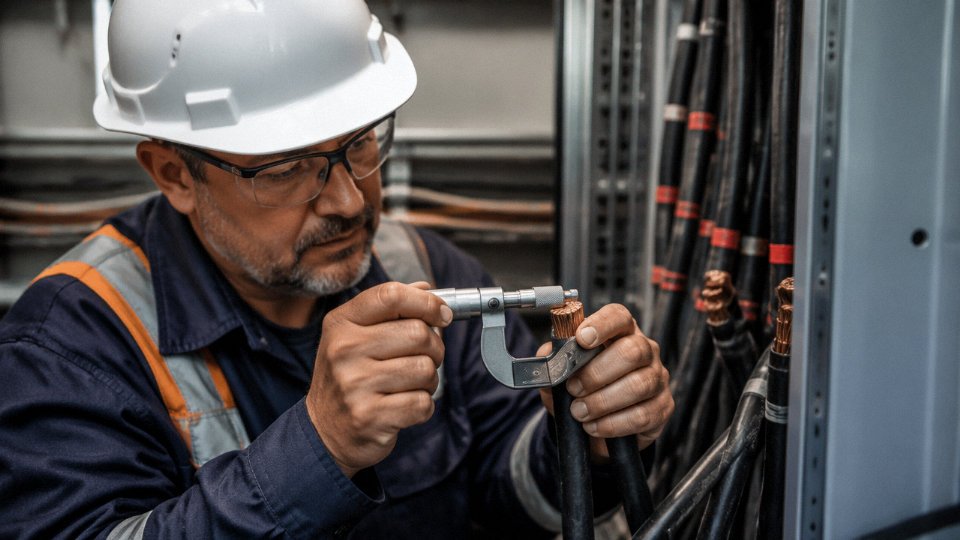
Pull out a calibrated micrometer and measure the overall cable diameter and, where the cable end is already stripped for termination, the individual conductor cross-section. Undersized conductors are the most common quality shortcut in substandard product — a conductor nominally marked 95 mm² measuring consistently around 88–90 mm² should raise an immediate flag.
Compare your readings against the manufacturer’s data sheet tolerances. IEC 60228 permits a minus tolerance on conductor resistance rather than on diameter directly, so pair dimensional checks with resistance measurements in Step 4. One check alone is not enough.
Step 3 — Insulation Resistance Test
Use a calibrated megohmmeter. For cables rated up to 1 kV, apply 500 V DC; for cables in the 3.3–6.6 kV class, use 1000 V DC. New low-voltage cable in good condition should return insulation resistance values well above 100 MΩ·km — many specifications set a minimum at 200 MΩ·km or higher depending on the insulation system. A reading that crawls in below 50 MΩ·km on brand-new cable, tested at ambient temperature, indicates a problem: moisture ingress at a cut end, insulation damage during unreeling, or a manufacturing defect.
Test conductor-to-conductor and conductor-to-screen (or armor) on every core. Record the stabilized reading at 60 seconds, not the initial deflection.
An insulation resistance test at the correct DC voltage is sufficient to verify medium-voltage cable condition before energization.False
IR testing is a necessary screening step but not sufficient on its own for medium-voltage cable. A power-frequency withstand test per IEC 60502-2 is required to stress the insulation at operating voltage and reveal defects that a low-voltage DC test will not excite.
Step 4 — Continuity and Conductor Resistance
Measure DC resistance per kilometer and compare against IEC 60228 maximum values for the declared conductor class and cross-section. A reading more than roughly 5% above the standard maximum suggests either an undersized conductor or a lower-purity conductor material — both are red flags in bulk procurement, particularly for cable sourced outside established supply chains.
Resistance climbs with temperature, so record ambient temperature at the time of measurement and apply the correction factor if the cable is warm from sitting in direct sun. It is an easy step to forget on a busy commissioning day.
Step 5 — High-Voltage Withstand Test
For medium-voltage cables, IEC 60502-2 specifies a 5-minute power-frequency withstand test before connection to switchgear. The test voltage depends on the U₀ rating — follow the table in the standard, not a rule of thumb. For installed low-voltage cables where a power-frequency test is impractical, a DC proof test per the project specification is the usual alternative, though DC proof testing on XLPE cables is a topic with genuine debate among commissioning engineers; some specifications now prefer very-low-frequency (VLF) testing instead.
Do not skip this step for medium-voltage installations on the grounds that the cable is new. New cable can carry a latent defect that only presents under voltage stress.
Step 6 — Screen and Armor Continuity
For screened or armored cables, measure end-to-end continuity of the metallic layers with a low-resistance ohmmeter. An open screen that reads infinite resistance almost always indicates either a manufacturing defect — a broken drain wire or interrupted foil — or installation damage at a pulling point. Either condition must be resolved before energization. A screen that floats electrically at one end provides no useful fault current return path and can leave personnel and equipment exposed during a phase-to-screen fault event.
Resistance values for the screen or armor braid should be consistent with the stated material and cross-section. Large deviations suggest inconsistent construction.
Documenting Results and Knowing When to Reject
Every measurement in steps 1 through 6 belongs in a test record that links the result to the cable drum serial number, the route identifier, and the test date. A spreadsheet with those four columns is the minimum; your project QA system may require more.
The rejection threshold is clear: any single measurement outside specification — whether that is a low IR reading, a conductor resistance above the IEC 60228 maximum, a failed withstand test, or an open screen — is cause to hold the cable out of service until it is replaced or the anomaly is formally disposition-reviewed by a qualified engineer. Commissioning pressure is real, but energizing a cable that has already failed a pre-commissioning test is a decision that tends to produce consequences far larger than the delay it was trying to avoid.
Frequently Asked Questions About Power Cable Compatibility
Can I use a higher-voltage-rated cable on a lower-voltage system?
Yes, without any technical downside. A cable rated 0.6/1 kV installed on a 400 V system has more insulation than the application demands — that is a safety margin, not a problem. In practice, procurement teams sometimes specify a higher-rated cable deliberately to get a particular physical construction, wall thickness, or jacket material that isn’t available in a lower-rated product line. The only consequence is modestly higher material cost, which on a large project is worth confirming against alternatives. You will never damage a system or a cable by over-rating on voltage.
My cable is rated 90°C but the ambient is only 35°C — can I run it at full rated ampacity?
Not automatically. The 90°C figure is the maximum conductor temperature, not the surrounding air temperature. Your actual ampacity depends on how the cable is installed — direct buried, in a duct, clipped to a tray, bunched with other cables — plus the number of cables grouped together and, for buried runs, the soil thermal resistivity. A single cable in free air derates very differently from six cables laid flat in a conduit. The rated temperature is the ceiling; installation conditions determine how close you can approach it. Always apply the derating factors from IEC 60364-5-52 or your applicable national table before finalizing conductor size.
Is aluminum conductor cable safe for industrial use?
Yes, when specified and terminated correctly. Aluminum has been used in industrial and utility installations for decades, and the material itself is not the problem. The issue is almost always at the termination. Aluminum work-hardens under screw pressure over time, the connection loosens, resistance rises, and you get heating. Use aluminum-rated compression lugs — not the copper-barrel lugs that are often sitting in the storeroom — and apply anti-oxidant compound to every connection before assembly. If someone on your site is using copper-rated fittings on aluminum conductors because “they’re the same size,” that is a fire risk waiting to develop.
Aluminum conductor cables are unsafe for industrial power systems.False
Aluminum conductors are widely used in industrial and utility power systems globally. Failures occur not from the conductor material itself but from incorrect termination practice — specifically, using copper-rated fittings without anti-oxidant compound on aluminum conductors.
What does LSZH mean and do I always need it?
LSZH stands for low-smoke zero-halogen. In a fire, conventional PVC releases hydrogen chloride gas, which is corrosive, toxic, and optically dense. LSZH compounds suppress that. It is mandatory in tunnels, underground transit systems, data centers, offshore platforms, and any enclosed public space where evacuation or equipment survival in a fire matters. In a well-ventilated outdoor substation or an open industrial yard, standard PVC is perfectly acceptable and meaningfully cheaper — sometimes 15–30% less on jacket cost alone, depending on cable size and compound pricing at the time. Specifying LSZH everywhere by default adds cost without adding protection in those contexts.
How do I verify that a cable from an overseas supplier actually meets IEC standards?
Ask for the full third-party type test report, not a summary page. That report should carry the testing laboratory’s ISO/IEC 17025 accreditation number. Cross-check that number on the laboratory’s public certification portal — it takes about two minutes and immediately separates legitimate reports from documents that merely look official. Then pull the measured values and compare them against the IEC limits yourself; don’t just read the pass/fail stamps. For orders above roughly a few container loads, a pre-shipment inspection by an independent body — SGS and Bureau Veritas are the standard choices for this — is worth the cost. Factory audits during production are even better for ongoing supply relationships.
Can I join two different cable types mid-run if they have the same voltage rating?
Voltage rating alone is not enough. The joint must be rated for both cable constructions and must use a type-tested joint kit designed for that combination. Joining XLPE-insulated cable to PVC-insulated cable in the same run is technically possible with the right kit, but most reputable installers avoid it in permanent installations because long-term performance at the interface depends heavily on installer qualification and how cleanly the joint is made. Where it is unavoidable — an extension to an existing run, for instance — document the joint location, use a properly certified kit, and ensure whoever does the work has done it before on that specific combination.
What is the minimum bend radius for power cables and why does it matter?
Armored power cables generally require a minimum bend radius of 8–12 times the overall cable diameter; flexible cables are typically 4–6 times. These numbers exist because cable geometry is engineered concentrically — bend tighter than the limit and conductor strands shift, insulation loses uniform wall thickness, and you create a mechanical stress concentration. That point will not fail immediately. It will fail after a few dozen thermal load cycles have worked the deformation, usually at the worst possible time. Pulling cable through conduit bends is where this most often goes wrong; the installer may not feel the resistance that signals an over-bend until damage is already done.
Does Jinda supply cables with dual certification for export to multiple countries?
Many product lines in the Jinda range are manufactured to IEC base standards with supplementary testing to satisfy specific market requirements — HAR marking for Europe, particular national approvals for the Middle East, and similar. The right answer for your project depends on the destination country, the applicable local regulation, and the end-use application, so a one-size answer here would be misleading. Contact Jinda’s technical sales team with your destination market and project specification; they can confirm which product constructions carry the necessary certifications and whether additional testing is required for your specific case.
Specifying and Sourcing Compatible Cables for Large-Scale International Projects
By the time a project reaches procurement, the hard compatibility decisions should already be locked in the design. In practice, they rarely are. Cable schedules arrive with gaps, specifications mix prescriptive requirements from three different national standards, and somebody has copied the voltage rating from a previous project on a different grid. Sorting that out during sourcing adds weeks you usually don’t have.
Performance Specs vs. Prescriptive Specs — and Why It Matters to Your Budget
A prescriptive specification names a exact construction: conductor stranding class, insulation thickness to the decimal, a specific national standard. That approach makes sense when you’re replicating an existing installation exactly. For most international projects, it quietly eliminates most of the competitive supplier base without actually improving technical quality — it just creates artificial scarcity.
A performance specification defines what the cable must do: voltage class per IEC 60502-2, minimum ampacity under defined installation conditions, maximum DC resistance per IEC 60228, fire performance to IEC 60332-3-24, and so on. Any manufacturer who can demonstrate compliance through type test reports becomes a qualified bidder. You get genuine price competition and, if you’ve written the spec well, no sacrifice in technical outcome. The IEC framework is mature enough that this approach works across most cable categories from low-voltage control cables right up to 36 kV distribution feeders.
What a Complete Cable Schedule Actually Contains
Incomplete cable schedules are probably the single largest source of avoidable procurement delays. A schedule that will actually support a clean, comparable quote needs: system voltage and circuit voltage (U₀/U), design current with the installation method used for ampacity calculation, route length and maximum allowable voltage drop as a percentage, ambient temperature and soil thermal resistivity for buried routes, any chemical or UV exposure, fire zone classification if applicable, required certification marks (CE, KEMA, CCC, or others depending on destination), and — critically — termination system compatibility. That last item gets dropped constantly. A perfectly specified cable that won’t accept the gland or lug already on site creates a commissioning problem at exactly the wrong moment.
Lead Times Are Not Negotiable After the Fact
Standard low-voltage cables from stock: a few days to a couple of weeks, depending on quantity. Medium-voltage XLPE cables in custom configurations, fire-resistant cables with mica taping, offshore-rated cables with specialized sheaths — plan on roughly 8 to 16 weeks from confirmed order to shipment. That range depends on conductor cross-section, insulation system, armoring type, and current production loading at the factory. Projects that don’t build this into the schedule end up expediting at a premium or, worse, sequencing installation around a missing cable and eating the delay cost in labor and crane time.
Batch Consistency: The Risk Nobody Budgets For
Type test certificates prove a cable design performs to spec. They say nothing about the reel that ships six months later. Conductor resistance, capacitance, insulation eccentricity, and overall diameter can all drift between production runs if the manufacturer doesn’t maintain tight process controls. On a large project, dimensional variation between early and late deliveries can affect pulling tension calculations and gland selections you’ve already committed to.
The practical mitigation is straightforward: require drum-by-drum routine test certificates as a contractual deliverable, not an optional attachment. Review the manufacturer’s ISO 9001 scope to confirm it covers the specific production lines making your cable, not just a head-office quality management system. A factory audit — even a desk audit reviewing recent calibration records, raw material traceability logs, and internal rejection rates — will tell you more than a certificate can.
Routine test reports issued per IEC 60502 cover conductor resistance, insulation resistance, voltage test, and continuity — one report per drum is standard practice at compliant manufacturers.True
IEC 60502-1 and IEC 60502-2 define routine tests as factory acceptance tests applied to every finished length; drum-by-drum reporting is the normal delivery requirement on specified projects and is not an unusual demand.
The Real Delivered Cost Calculation
A cable quoted 15% below the nearest competitor looks attractive in a line-item comparison. Run the full calculation before awarding. If that cable delivers 5–8% fewer usable meters per drum due to tighter winding or higher rejections at termination, has conductor resistance 4–6% above the nominal IEC 60228 value (reducing effective ampacity), and arrives without traceable test documentation that your client’s engineer will accept — the rework, additional drums, and potential re-inspection costs typically exceed the original saving by a meaningful margin. The comparison isn’t cable price per meter; it’s installed, commissioned, and accepted circuit per dollar.
Jinda’s Supply Capability for Project-Scale Procurement
Shandong Jinda operates five production bases across China with a combined 470,000 m² of manufacturing space, which in practice means the capacity to handle orders ranging from single-reel samples for qualification testing through to multi-thousand-ton project lots without subcontracting core production. In-house R&D supports custom constructions when a standard catalogue item doesn’t quite fit — a specific voltage/temperature combination for a desert substation, a modified armor configuration for a shallow offshore trench, a fire-resistant variant that needs to meet two overlapping national standards simultaneously. The export logistics team handles LC documentation, certificate of origin, third-party inspection coordination, and delivery scheduling to customers across more than 50 countries, which matters more than it sounds when a delayed shipment at customs is holding up an energization date.
If you have a cable schedule or a project specification — even a draft one — Jinda’s technical team will review it for compatibility issues and return a detailed quotation. That review is free, and it frequently catches specification conflicts or lead-time exposures before they become procurement emergencies. Reach out directly with your schedule and they’ll treat it as a technical conversation, not a sales call.