Mislabeling a power cable as a control cable — or vice versa — is not just a paperwork error. Wire the wrong conductor cross-section into a motor control circuit and you risk insulation breakdown under load, nuisance trips, or a smoldering junction box nobody finds until a shift changeover. Do it at scale, across a plant retrofit or a bulk procurement order, and you’re looking at rework costs, schedule slippage, and the kind of audit finding that follows a project manager for years.
Power cables and control cables differ in conductor size, core count, voltage rating, and construction. Power cables carry load current to motors, panels, and equipment — conductors typically run 1.5 mm² to 1000 mm² or larger, rated from 0.6/1 kV up to 500 kV, usually with 1 to 5 cores. Control cables transmit signals and switching commands — conductors are smaller, commonly 0.5 mm² to 10 mm², rated at 450/750 V or 0.6/1 kV, and may contain anywhere from 2 to 61 cores.
What makes this genuinely tricky in practice is that the two cable types can look nearly identical on a reel end, especially at the 1.5 mm² to 2.5 mm² overlap where both types are manufactured to similar outer diameters and jacket colors. Knowing exactly where to look — and what each marking actually means — is where the real skill sits.
Core Function and Circuit Role: The Fastest First-Pass Test
Before you unroll a single meter of cable or read a single label, you can usually classify a cable correctly just by answering one question about the circuit it serves. That conceptual filter saves time at the design stage and prevents the kind of substitution errors that cause failures months after commissioning.
What a Power Cable Is Actually Doing
A power cable’s job is to move bulk electrical energy — kilowatts or megawatts — from a source to a load that converts that energy into mechanical motion, heat, or light. Think of the feed from a main switchboard to a 200 kW crusher motor, the cable running from a transformer secondary to a distribution panel, or the supply conductors feeding a bank of furnace heating elements. The current involved is substantial: tens to hundreds of amperes depending on load and voltage level. The voltages span from 0.6/1 kV for most industrial low-voltage systems all the way up to 500 kV for transmission-class cables governed by IEC 60502 and related standards. At these levels, insulation failure doesn’t just cause equipment damage — it kills people. That’s not hyperbole; it’s the design constraint that drives the heavier insulation walls, larger conductor cross-sections (commonly 1.5 mm² up to 400 mm² or beyond in industrial work, though I’ve specified 630 mm² and 1000 mm² conductors on large substation projects), and the strict voltage-rating markings you’ll see printed on the outer sheath.
What a Control Cable Is Actually Doing
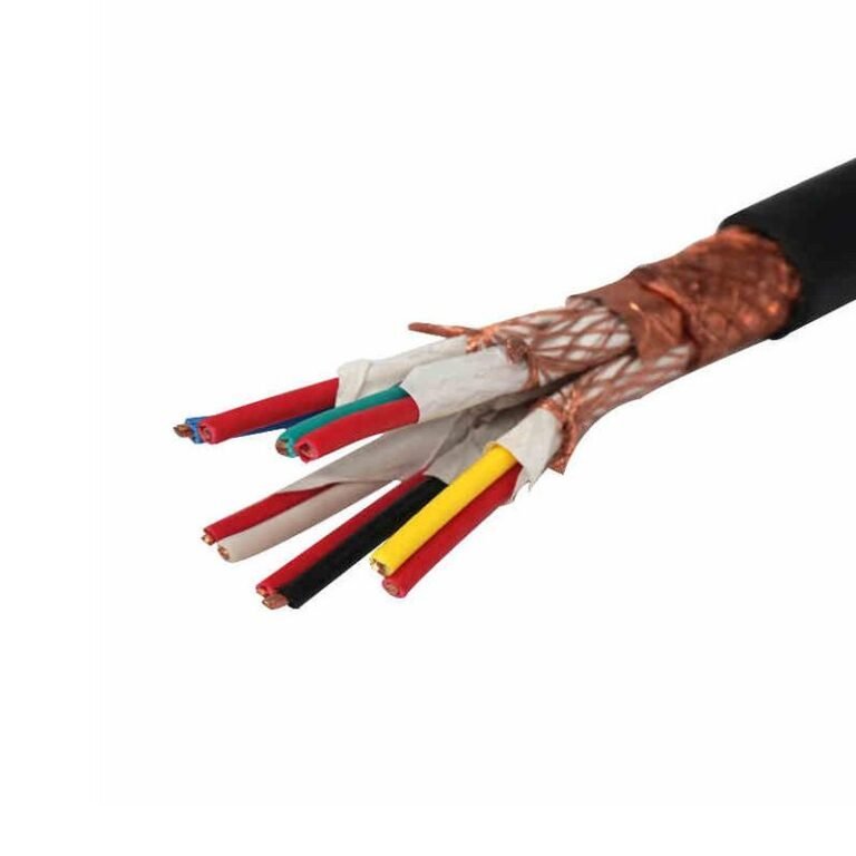
Control cables move information, not energy. They carry relay contact signals, 4–20 mA instrument loops, PLC digital I/O states, solenoid valve commands, and interlock signals. The currents involved are typically in the milliamp range. Operating voltages are usually 24 V DC for modern PLC I/O, or up to 230 V AC for older relay logic — in practice almost never above 250 V AC in signal service. IEC 60227 and IEC 60228 cover the conductor and insulation requirements for this cable family. Because the energy level is low, the insulation doesn’t need to handle the same dielectric stress as a power cable, but control cables have their own demands: more cores (commonly 4 to 37 in industrial plants, sometimes 61 in instrument-dense processes), tighter capacitance requirements on long runs, and often an overall screen to reject interference from nearby power cables.
The Practical Circuit-Level Test
Ask yourself: Is this cable moving energy to perform mechanical or thermal work, or is it moving a signal to command a device?
A variable frequency drive installation makes the distinction vivid. The VFD has two completely separate cable connections. The power feed — three-phase supply from the panel to the drive input, and the motor cable from the drive output to the motor terminals — is power cable: heavy conductors, rated at 0.6/1 kV or higher, sized by current-carrying capacity and voltage drop. The control wiring running from the PLC analog output card to the VFD speed-reference terminal, or from a run/stop relay contact to the drive’s digital input, is control cable: possibly a 2-core or 4-core screened cable, 1.0 mm² or 1.5 mm² conductors, carrying nothing more than a 0–10 V or 4–20 mA signal. Substituting one for the other in either direction causes problems — undersized power cable overheats, and unscreened power cable used as control wiring picks up noise that causes erratic drive behavior or nuisance trips.
When Both Types Share the Same Installation
In most real plants, power cables and control cables run together in the same cable trays, conduit banks, or trenches — often physically adjacent. That’s where conceptual clarity alone stops being enough. You need to be able to identify each type by sight, by markings, and by construction. Knowing the functional distinction first, though, means you approach that physical identification with the right mental model already in place rather than guessing from appearance alone.
IEC 60502 covers power cables rated 1 kV and above, while IEC 60227 and IEC 60228 address lower-voltage wiring and flexible control cables respectively.True
IEC 60502-1 applies to extruded solid dielectric insulated power cables for rated voltages from 1 kV up to 30 kV; IEC 60502-2 extends coverage to 150 kV. IEC 60227 covers PVC-insulated cables of rated voltages up to and including 450/750 V, and IEC 60228 specifies conductor requirements for insulated cables including flexible and control types.
Conductor Size, Core Count, and Cross-Section: Reading the Physical Evidence
Cut the end of an unknown cable and you already have most of the information you need. The physical dimensions — conductor cross-section, core count, and the way the conductors are stranded — tell a consistent story once you know what to look for.
Cross-Section Ranges and Why They Exist
The gap between power cable and control cable conductor sizes is not arbitrary. It follows directly from the current each type must carry continuously without overheating.
| Cable Type | Typical Conductor Cross-Section | What Drives That Range |
|---|---|---|
| Power cable | 1.5 mm² up to 1,000 mm² or larger | Must carry load current — motors, transformers, distribution feeders — where thermal duty is the governing constraint |
| Control cable | 0.5 mm² to 10 mm², most commonly 1.5–4 mm² | Carries signal and switching current only; voltage drop and loop resistance matter more than ampacity |
In practice, the overwhelming majority of control cable installations sit between 1.5 mm² and 2.5 mm² per conductor. You rarely see 10 mm² control cable outside of very long signal runs or older installations where the engineer over-specified to reduce resistance. Power cable below 6 mm² exists — lighting and small branch circuits — but once you’re looking at anything 16 mm² and above, you’re almost certainly looking at a power circuit. That’s just how load calculations work out.
Core Count: The Clearest Visual Clue
Power cables are structurally simple. A standard three-phase system needs L1, L2, L3, a neutral, and a protective earth — that’s five conductors at most, and single-phase circuits need even fewer. Four-core YJV (three phases plus combined N/PE) and five-core configurations cover the vast majority of LV power distribution. Going beyond five cores in a true power cable is unusual enough that it should prompt a second look at the application.
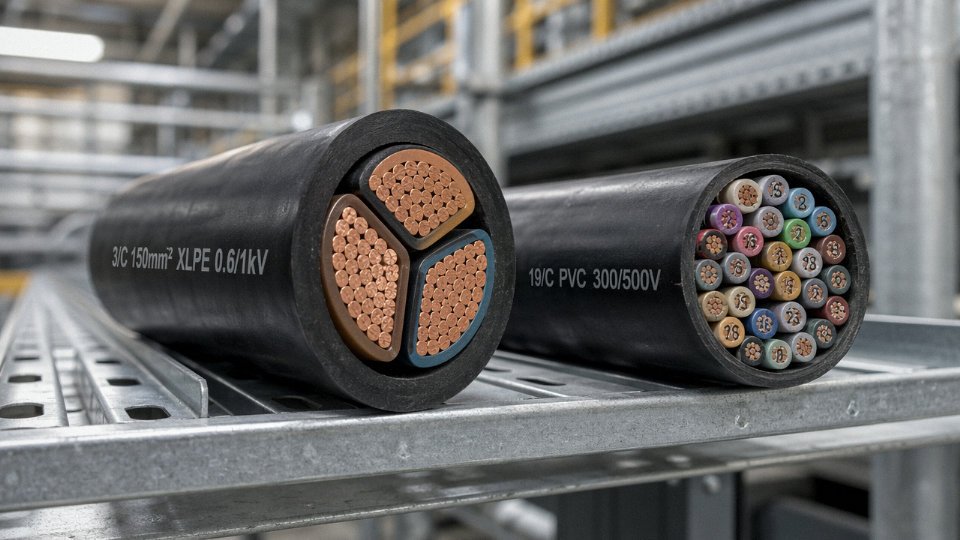
Control cables are the opposite. Multi-point interlock circuits, PLC I/O loops, instrument signal wiring, motor control center wiring — all of these demand individual conductors for each discrete signal. A medium-complexity control panel might easily consume a 19-core or 27-core run in a single cable tray. Jinda’s KVV and KVVP series, for instance, are produced in standard core configurations of 4, 7, 10, 12, 14, 19, 24, 27, 37, and 61 cores. That range exists because real automation systems need it. A 61-core control cable is not exotic; it’s a practical packaging solution for a dense signal bundle routed between a remote junction box and a central marshalling cabinet.
Control cables routinely reach 61 cores in industrial automation applicationsTrue
Multi-core control cables with 37, 61, or more conductors are standard catalog items used in process plants, substations, and large motor control centers to consolidate signal wiring into a single routed bundle. IEC and national standards cover these configurations explicitly.
Stranding Architecture: How the Conductors Are Built
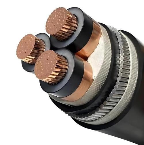
This is where a magnifying glass or a clean cross-section cut becomes useful. Large power cable conductors — anything above roughly 150–185 mm² — frequently use sector-shaped conductors rather than round ones. Three sector-shaped conductors pack together into a smaller overall cable diameter, which saves material and conduit space. At very large cross-sections (300 mm² and above), Milliken construction — where the conductor is divided into six or more stranded segments twisted together — further reduces AC resistance from skin and proximity effects. You will not see this in a control cable. Ever.
Control cable conductors are fine-stranded throughout. The individual wire strands are small — often 0.2–0.4 mm diameter — because these cables get repeatedly bent during installation, terminated into small terminal blocks, and occasionally re-terminated during maintenance. Flexibility is the design requirement, not current density.
A Field Test That Takes Ten Seconds
If you can close your hand comfortably around the cable and it has more than six conductors visible at the cut end, it’s almost certainly a control cable. If the conductor itself — just the copper or aluminum, not the insulation — is thicker than your thumb, you’re holding a power cable, full stop. That’s not a rigorous test, but it has sorted out more than a few “unknown cable” situations during cable tray audits where the original labels had worn off.
Jinda’s ZR-YJV flame-retardant power cables and standard YJV XLPE-insulated power cables sit at the large conductor end of this spectrum, while the KVV (PVC-insulated, PVC-sheathed) and KVVP (with overall copper braid screen) control cable series represent the multi-core, fine-stranded end. Looking at both side by side makes the dimensional difference immediately obvious — which is exactly the kind of reference comparison worth keeping in a procurement or site engineer’s file.
Voltage Rating, Insulation Material, and Jacket Color Coding
Walk into any large cable yard and you’ll find drums stacked without labels, jackets faded by UV, and cut ends that look deceptively similar. Voltage markings, insulation material, and color coding are the next layer of identification — and together they’re more reliable than a quick visual once you know what to read.
Reading the U0/U Voltage Marking
Every compliant cable drum and datasheet carries a voltage designation in the format U0/U, sometimes extended to U0/U (Um). U0 is the rated voltage between conductor and earth (or screen); U is the rated voltage between conductors. A cable marked 0.6/1 kV is rated for systems up to 1 kV phase-to-phase — that’s your standard low-voltage power cable and the ceiling for most control cables as well. Control cables typically sit at 0.45/0.75 kV or 0.6/1 kV. Medium-voltage power cables step up to 6/10 kV, 8.7/15 kV, 26/35 kV, and higher — up to 127/220 kV for transmission-class cables.
The consequence of getting this wrong isn’t subtle. Install a 0.6/1 kV control cable in a 6 kV feeder circuit and the insulation will fail — possibly within hours under full operating voltage, sometimes catastrophically, depending on how close the system runs to rated voltage and how long the fault takes to clear. In practice, the failure is rarely a clean trip; it tends to arc, carbonize the jacket, and take neighboring cables with it.
Operating a cable above its rated U0/U voltage will cause progressive insulation degradation or immediate breakdown, depending on the overvoltage magnitude and duration.True
Insulation systems are designed with specific dielectric strength margins for their rated voltage class. Exceeding U0 accelerates electrothermal aging and can initiate partial discharge, leading to premature failure or flashover.
Insulation Polymer: What the Material Tells You
The insulation compound isn’t just a mechanical choice — it’s a voltage and temperature class indicator.
| Insulation Material | Typical Application | Max Conductor Temp | Voltage Range |
|---|---|---|---|
| PVC | Low-voltage power and control cables | 70 °C (continuous) | 0.45/0.75 kV – 0.6/1 kV |
| XLPE | Medium- and high-voltage power cables | 90 °C (continuous), 250 °C (short-circuit) | 0.6/1 kV – 500 kV |
| EPR | Flexible power cables, mining, marine | 90 °C (continuous) | 0.6/1 kV – 36 kV typically |
| PE | Direct-burial power cables | 70–75 °C | 0.6/1 kV and above |
XLPE dominates anything above 1 kV. If you strip back a cable jacket and find a firm, slightly waxy insulation that doesn’t soften readily when heated — that’s almost certainly XLPE, and you’re almost certainly looking at a power cable. PVC is softer, smells faintly acrid when scratched, and is common in both low-voltage power and control cables, which is exactly why polymer alone doesn’t finish the identification.
Core Insulation Colors: IEC 60446 and What It Shows You
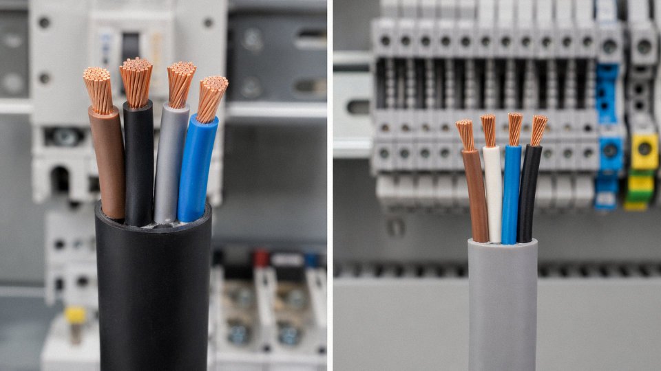
Under IEC 60446, three-phase power cable cores use brown, black, and grey for L1, L2, and L3, with green-yellow striped insulation reserved exclusively for the protective earth conductor. Neutral, where present, is blue. This applies to single-phase and three-phase configurations up through the 0.6/1 kV range.
Control cables look completely different on the cut end. Instead of three or four distinctly colored large conductors, you’re looking at anywhere from 2 to 20-plus small-gauge cores — usually numerically printed (core 1, core 2, and so on) with a repeating base color scheme or sequential color pairs. The printing is the giveaway. Power cable cores don’t get numbered; control cable cores almost always do, because you need to trace individual signal or pilot circuits back to terminal blocks.
Outer Jacket Color: Useful Guide, Not a Hard Rule
Industrial power cables commonly arrive with a black or dark grey outer jacket — practical for UV resistance in exposed installations. Control cables in many manufacturers’ standard ranges use grey, light grey, or occasionally orange jackets, and some instrumentation cable lines use blue or green to distinguish them at a glance on cable trays.
Here’s the operational warning, though: jacket color is not standardized across manufacturers the way core colors are under IEC 60446. A grey jacket from one supplier might be their standard power cable; grey from another is their control cable range. Orange means high-visibility EV charging cable to one manufacturer and flexible mining cable to another.
In a single-supplier, well-documented installation, jacket color is a useful quick-check. In a mixed-supplier plant — which describes most real industrial facilities after a decade of expansions and emergency procurement — always cross-reference the printed cable marking on the jacket itself, the drum label, and the as-built documentation before making any identification decision. The printed legend (manufacturer, voltage rating, construction, standard) runs the full length of the cable and doesn’t lie, even when colors do.
Shield, Armor, and Mechanical Protection Layers: Structural Clues That Tell a Story
Once you get past conductor size and voltage rating, the shielding and armoring layers are probably the most reliable physical identifiers you have — and they reveal something more useful than just “what type is this cable.” They tell you what the cable designer was actually worried about.
Why Control Cables Are Shielded and Power Cables Are Armored (and Why That Difference Matters)
Control cables carry low-level signals — 4–20 mA loops, 24 V DC logic, RTD or thermocouple circuits — that are genuinely vulnerable to electromagnetic interference from nearby power conductors, variable-frequency drives, and motor starters. An overall copper braid shield, or an aluminum-foil-plus-braid combination, wraps the entire conductor bundle to provide a continuous Faraday cage. Drain that shield to a single, clean earth point and you suppress the noise that would otherwise corrupt your signal. This is the engineering reason for the shield; it has nothing to do with tensile strength or ground-fault protection.
Power cables, by contrast, carry currents that don’t care much about EMI pickup — but they do get pulled hard through conduit, buried in trenches, and occasionally hit with a shovel. Steel wire armor (SWA) or steel tape armor (STA) is there to resist those mechanical insults: abrasion, impact, rodent damage, the sidewall pressure that develops when you pull a heavy cable around a bend. The protection priority is entirely physical, not electromagnetic.
An overall copper braid shield on a control cable provides effective EMI/RFI rejection primarily when terminated at a single earth point; grounding both ends in a non-isolated system creates a ground loop that can worsen noise.True
Single-end earthing of a cable shield is standard practice in instrumentation to prevent circulating currents. Dual earthing is only used intentionally in specific high-frequency or safety-earthing arrangements.
Individually Shielded Pairs and Triads — a Control Cable Feature You Won’t Find in Power Cable
Some instrumentation-grade control cables go further than an overall shield. Inside a cable like a KVVP2-22, each signal pair or triad has its own individual foil or braid shield, in addition to the overall screen. This is common where you need to run multiple independent instrument loops in a single cable run without crosstalk between channels. There is no equivalent structure in standard power cable construction — the concept simply doesn’t apply. If you unroll the outer sheath and find individually wrapped sub-bundles inside their own foil layers, you are definitely looking at instrumentation or control cable, full stop.
Armor Wire Gauge Tells You More Than You’d Expect
Power cable SWA wires are heavy: typically 2.0 mm to 4.0 mm in diameter, depending on the overall cable diameter and the installation tensile-load requirement. You can feel the difference with your fingers. Control cable armor wires run finer — roughly 0.8 mm to 1.6 mm — because the tensile loads during a tray or conduit pull are modest and the armor is mostly there for incidental mechanical protection rather than serious installation stress. Misidentifying a control cable as a power cable because both have steel wire armor is a surprisingly common error on mixed-service procurement lists. The wire gauge and the feel of the cable’s stiffness will resolve the ambiguity quickly.
The Outer Sheath and Bedding Layer
Power cable outer sheaths are extruded thick — often 2.0 mm to 3.5 mm of PVC or HDPE — because buried or direct-contact installations demand it. Control cable sheaths are thinner, usually optimized for indoor cable tray, conduit, or panel wiring where ground-contact durability is less of a concern.
The bedding layer under the armor follows the same logic. On a power cable it is a substantial extruded layer, sometimes with a defined minimum thickness in the standard. On a control cable it tends to be lighter, because the overall cable is smaller and the mechanical role of the bedding is proportionally reduced.
The Field Cut Test
If you are on site with an unidentified cable and no datasheet, score through the outer sheath carefully with a cable knife. What you see next is diagnostic. A metallic braid — or a crinkled foil wrap with a bare drain wire — surrounding a bundle of many small, numbered, color-coded conductors means you have a shielded control cable. If instead you expose two to five large-diameter conductors, either sector-shaped or round, sitting under a layer of steel armor, that is a power cable. The difference is not subtle once you know what to look for. In my experience this single physical check resolves about 90% of ambiguous field identifications faster than hunting down documentation.
Cable Marking, Print Legends, and Nameplate Decoding: The Definitive Method
If you have physical access to the cable — whether on a drum at goods-in, already pulled through a tray, or coiled in a substation — the printed or embossed legend on the outer sheath is the single most reliable identification tool you have. Everything else (conductor size, core count, jacket color) is circumstantial. The legend is definitive, provided you know how to read it.
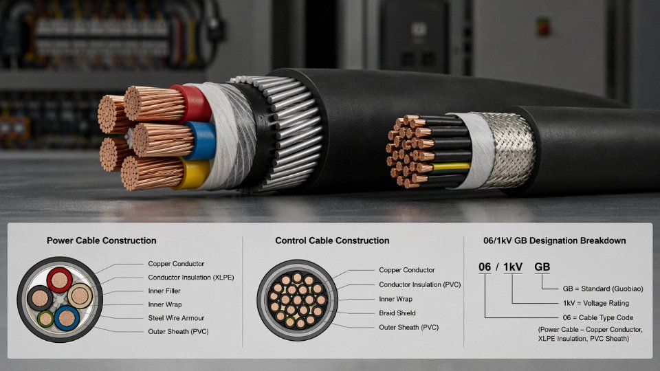
Decoding the GB Cable Designation System
China’s GB standard cable markings follow a structured alphanumeric sequence. Each character or group has a fixed meaning, and once you learn the grammar, a long cable code stops looking like a random string.
Take a typical medium-capacity power cable: ZR-YJV22-0.6/1kV 3×185+1×95
Breaking that down left to right: ZR is a prefix meaning flame-retardant (from “阻燃”, but in export documentation always written ZR). YJ means XLPE insulation — cross-linked polyethylene, which is essentially the signature insulation of modern medium and high-voltage power cables. V here is the PVC outer sheath. 22 designates double steel tape armor with a PVC bedding layer — common in direct-burial and industrial tray installations. 0.6/1kV is the rated voltage, phase-to-ground and phase-to-phase. Then 3×185+1×95 tells you three main conductors at 185 mm² plus one reduced neutral at 95 mm². That last part alone — three large power conductors plus a neutral — makes it unambiguously a power cable.
Now contrast that with a typical control cable designation: KVVP2-22-450/750V 14×1.5
The K prefix is the most immediate signal. In the GB system, K at the start of a code means control cable, full stop. VV tells you PVC insulation and PVC sheath. P2 is copper braid shielding — important for noise rejection in instrumentation loops. 22 again is steel tape armor. 450/750V is the voltage class, noticeably lower than any power cable. And 14×1.5 means fourteen cores, each 1.5 mm². Fourteen cores carrying 1.5 mm² conductors for logic signals and relay outputs — there is no other interpretation.
The practical shortcut: see a K at the front, it’s control. See YJ anywhere in the insulation field, it’s power class. A lone V as the first non-prefix letter could go either way, so keep reading.
IEC and European Designation Cross-Reference
European specifications use different notation but the same underlying logic. N2XSY — a single-core medium-voltage power cable — breaks down as: N (German standard base), 2X (XLPE insulation), S (copper wire screen), Y (PVC outer sheath). You will see this on MV distribution projects across Europe and in many African and Middle Eastern tenders that follow IEC 60502.
For flexible control and signal cables, YSLCY-JZ is a common European type: Y (PVC insulation), SL (foil + braid shielding), CY (copper braid), JZ indicating multicore flexible control use. The multicore flexible construction and the shielding notation together signal the control/signal family immediately, just as K does in GB.
Mapping between the two systems takes a minute but it’s worth doing during procurement review — a European end-client spec calling for N2XSY and a Chinese factory offering ZR-YJV-equivalent product are not automatically interchangeable without checking the copper purity grade, screen cross-section, and jacket compound against the project’s fire performance requirements.
Jinda prints full GB and IEC-compatible markings on all cable sheaths and supplies complete test reports and certificates for customs clearance and project compliance.True
This is standard practice for export-grade cable manufacturers supplying international EPC and procurement projects; third-party test documentation is routinely required for customs and project commissioning in most markets.
Practical Documentation Habits That Prevent Expensive Mistakes
Photograph the drum label and a clear shot of the printed sheath legend at goods receipt. Do it before the drum moves to the laydown area. Store those images in the project folder alongside the test certificates. This sounds obvious, but in practice — especially on projects with fifty or more cable types — drums get separated from their paperwork, installation crews peel drums down to the last few meters, and the only record of what cable was installed in a given tray is what someone wrote in a commissioning log two years ago.
During maintenance, when a fault forces a section splice, that sheath photograph is the difference between a correct repair and installing a 450/750 V control cable into a circuit that runs at 0.6/1 kV. The downtime cost of getting that wrong is steep. The cost of taking the photo is nothing.
Electrical Testing Methods to Confirm Cable Type When Markings Are Missing or Damaged
Faded print legends, fire-damaged sheaths, decades of UV exposure, or simply someone painting over a cable run — any of these can leave you staring at an unmarked cable with no reliable way to identify it visually. In older industrial plants, this happens more than anyone likes to admit. Before you guess, before you assume based on color, run a short sequence of electrical tests. The whole protocol takes under an hour on a typical run and gives you defensible, documented evidence of cable type.
Lock out, tag out, and verify the cable is fully de-energized before touching it. That step is non-negotiable regardless of what the test sequence is. Never assume a cable is dead because a breaker looks open.
Step 1 — Insulation Resistance Test
Start with a calibrated megohmmeter. Use 500 V DC test voltage for cables rated up to 1 kV, and 1000 V DC for anything you suspect might be a medium-voltage power cable. A healthy power cable in reasonable condition will typically show insulation resistance above 100 MΩ per conductor-to-ground, often several hundred MΩ or higher depending on cable age, temperature, and moisture exposure. Control cables will also show high IR values when the insulation is intact, so the IR number alone rarely separates the two types definitively.
What the IR test does tell you is insulation wall thickness — indirectly. After the test, physically measure the insulation wall on an exposed end with a digital caliper. Power cable insulation walls run roughly 1.5 mm to 4 mm or more depending on voltage class; control cable insulation walls are typically 0.6 mm to 1 mm. That difference is immediately obvious once you look for it.
Step 2 — Conductor DC Resistance Measurement
This is probably the most conclusive single test. A low-resistance ohmmeter (sometimes called a micro-ohmmeter or DLRO) measures the conductor resistance in Ω/km when you know the cable length, or you can extrapolate from a known sample length. Cross-reference the result against IEC 60228 resistance tables. A reading around 0.0754 Ω/km points directly at a 240 mm² Class 2 stranded conductor — that is a large power cable, full stop. A reading around 12.1 Ω/km matches 1.5 mm² conductor, which sits squarely in control cable territory.
In practice, you rarely have exactly 1 km of cable to test. Measure the actual length with a cable drum counter or a TDR (time-domain reflectometer if available), calculate the normalized value, and compare. Even a rough estimate gets you close enough to distinguish a 16 mm² power conductor from a 2.5 mm² control conductor — their resistance values differ by a factor of roughly six.
Step 3 — Inter-Core Capacitance Measurement
An LCR meter set to measure capacitance at 1 kHz between any two conductor pairs gives you another useful data point. Control cables tend to show higher capacitance per unit length than power cables of similar voltage class, largely because the cores are packed more tightly and the individual insulation walls are thinner. Values vary considerably by manufacturer and construction, so compare your readings against a published datasheet for the suspected cable type rather than a generic threshold. If you can find the manufacturer’s original spec sheet — even for a similar product — a capacitance match narrows the identification substantially.
Control cables generally exhibit higher inter-core capacitance per meter than power cables of the same voltage class due to tighter core spacing and thinner individual insulation.True
Capacitance between conductors increases with closer spacing and decreases with thicker dielectric; control cable construction (many small closely-packed cores, thin insulation) produces higher capacitance per unit length than the widely-spaced large conductors typical of power cables.
Step 4 — Shield Continuity and Configuration
If there is metallic shielding present, measure its end-to-end resistance with a low-resistance ohmmeter. A single continuous foil or braid wrapping all cores together, showing a few ohms across a reasonable cable length, is the typical signature of a shielded control or instrumentation cable. Individual shields around each core pair usually indicate an instrumentation cable rather than a standard control or power cable. Power cables, particularly those with SWA (steel wire armour) or aluminium wire armour, will show a measurable resistance across the armour, but the armour sits outside the insulation system as a mechanical layer — distinct from the signal-integrity shielding in control cables.
Document every test result with cable length, ambient temperature at time of test, and instrument serial number. If you are working in a regulated environment — petrochemical, pharmaceutical, utilities — that documentation may be required before the cable is re-energized anyway. A one-page test record per cable run is not bureaucracy; it is protection.
Comparison Table: Power Cable vs. Control Cable — 12 Identification Parameters at a Glance
The sections above walk through each identifier in depth. This table collapses all of it into one reference you can print and keep in a site binder or forward to a procurement team reviewing a bill of materials. Every range here carries a dependency — cross-sections depend on load calculations, core counts depend on system architecture, sheath thickness depends on voltage class and armor configuration. Treat the ranges as decision boundaries, not hard rules.
| # | Parameter | Power Cable | Control Cable | Common Mistake |
|---|---|---|---|---|
| 1 | Primary function | Carry load current to motors, transformers, distribution boards | Transmit switching signals, interlocks, instrumentation, protection commands | Treating any multi-core cable as “control” — a 3-core 35 mm² is a power cable serving a motor, not a signal run |
| 2 | Voltage rating | 0.6/1 kV up to 500 kV; MV cables commonly 6/10 kV to 26/35 kV | Usually 450/750 V or 0.6/1 kV; rarely higher | Assuming a 0.6/1 kV rating means the cable is a control cable — most low-voltage power cables share that same rating class |
| 3 | Conductor cross-section | 1.5 mm² to 1,000 mm² or larger; distribution feeders typically 35–300 mm²; final circuits often 1.5–16 mm² | 0.5 mm² to 10 mm²; most designs cluster around 0.75–4 mm² | A 5-core 2.5 mm² cable is frequently misread as a control cable — always confirm voltage rating and check whether cores are color-coded for phase/neutral/earth |
| 4 | Typical core count | 1 to 5 cores (single-phase, three-phase ± neutral ± earth); rarely more | 2 to 61 cores; 7, 10, 14, 19, 27, 37-core configurations are standard catalog items | High core count alone does not confirm control cable — some specialized power cables carry parallel conductors in multi-core arrangements |
| 5 | Insulation material | XLPE dominant above 1 kV; PVC at low voltage; EPR where flexibility or wet conditions apply | PVC very common at 450/750 V; XLPE used where heat resistance or longer runs demand it | PVC insulation is not a control-cable indicator; most LV power cables also use PVC |
| 6 | Armor and shield type | SWA (steel wire armor) or DSTA for mechanical protection; no overall screen needed for power distribution | Overall copper braid or tape screen common for EMI suppression; SWA less frequent, usually only for direct burial | Presence of a copper screen is a strong control-cable signal — screened power cables exist but are uncommon in standard distribution |
| 7 | Outer sheath thickness | Heavier — roughly 1.8–4 mm depending on voltage class and armor; MV cables noticeably thicker | Lighter — typically 1.0–2.5 mm; overall diameter compact relative to conductor area | Judging cable type by sheath thickness alone is unreliable; always combine with conductor inspection |
| 8 | Conductor shape | Sector-shaped conductors common above roughly 25 mm² to reduce overall diameter; fine-stranded for flexible versions | Round conductors almost exclusively; fine-stranded (Class 5) where repeated flexing occurs | Sector conductors definitively indicate a power cable — no control cable uses them |
| 9 | Typical applications | Main switchboard feeders, motor power circuits, transformer secondaries, busduct risers | PLC I/O wiring, relay panels, actuator feedback loops, instrumentation loops, fire alarm circuits | Motor control panel wiring runs both types in the same tray — segregate by function, not by proximity |
| 10 | Applicable standards | IEC 60502 (1 kV–30 kV), IEC 60228 conductors, GB/T 12706 (China LV/MV power) | IEC 60227, IEC 60092-376 (marine), GB/T 9330 (China control cable) | Quoting “IEC 60502” on a control cable spec sheet is a red flag — check the standard before approving a procurement submission |
| 11 | Designation prefix clues | YJV, VV, N2XY, XLPE/SWA/PVC; voltage class appears as “0.6/1kV”, “8.7/15kV” etc. in print legend | KVV, KVVP, KYJV (GB); CKVV for marine; “450/750V” typically printed on sheath | “K” prefix in Chinese GB designations reliably signals a control cable; absence of “K” does not confirm power cable — verify the full code |
| 12 | Field confirmation test | Insulation resistance (Megger at 1,000 V DC for LV), conductor resistance per IEC 60228, continuity check | Insulation resistance (500 V DC sufficient for 450/750 V rated cable), loop resistance, shield continuity if screened | Using a 1,000 V Megger on a 450/750 V rated control cable risks degrading aged insulation — match test voltage to cable rating |
Sector-shaped conductors are exclusive to power cables and never appear in standard control cables.True
Sector conductors are used in multi-core power cables above roughly 25 mm² to pack conductors more efficiently and reduce overall cable diameter. Control cables carry small cross-sections where this geometry offers no benefit, and no published standard specifies sector conductors for control cable construction.
One honest caveat: the “common mistakes” column reflects what actually shows up during site audits and goods-receipt inspections. The 5-core 2.5 mm² confusion is probably the most frequent, especially on projects where the same contractor handles both power and instrumentation work and cable labeling gets rushed.
For project-specific cable selection — particularly where cross-referencing GB, IEC, and customer specs simultaneously, or where a mixed power-and-control bundle needs to be optimized for tray fill and derating — Jinda’s technical team works through those calculations directly. The product catalogue covers standard configurations from LV power to screened control, and the engineering support desk can confirm designation codes, test certificates, and delivery schedules for bulk procurement. Reach out through the contact page for a specification review before finalizing your bill of materials.
Real-World Application Scenarios: Choosing and Identifying the Right Cable on Industrial Projects
Theory is clean. A congested cable tray at 2 a.m. during commissioning is not.
The three scenarios below come from project types Jinda regularly supplies. Each one puts the identification methods from earlier sections under real operational pressure — space constraints, missing labels, mixed voltage classes, and the kind of time pressure that turns a simple cable check into a consequential decision.
Offshore Oil Platform Electrical Fit-Out
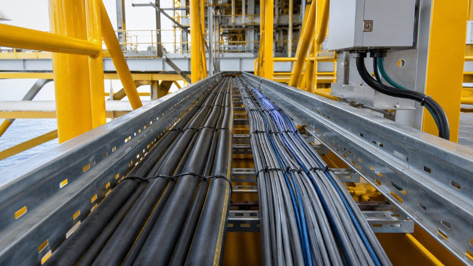
On a platform topsides, the main switchboard feeds motor control centers via 6.6 kV three-core armored cables — typically something like YJV42, 3×95 mm², with a double steel wire armor layer and an overall polyethylene outer sheath. Running through the same cable trays, often zip-tied to the same support brackets, are KVVP multicore control cables (19×1.5 mm²) carrying PLC signals to valve actuators and field instruments.
At first glance, both can look like “big grey cables” once they’ve accumulated a layer of grime and salt spray. But pull them apart on any accessible section and the differences are immediate. The 6.6 kV power cable’s armor wires are noticeably heavier — individual steel wires in the 2–3 mm diameter range rather than the lighter-gauge braiding or thin flat-wire armor typical of a KVVP. Cut or expose the end of the MV cable and you’ll find three conductors only, each with a thick XLPE insulation wall (roughly 4–5 mm at that voltage class, depending on manufacturer), a semiconducting layer underneath, and a copper tape screen around each core. Count the cores on the control cable: nineteen. No MV power cable runs nineteen cores.
Where markings survived, the sheath print told the full story — voltage designation, conductor cross-section, and cable type code. Where they didn’t, the three methods that proved most reliable were: (1) core count, (2) armor wire gauge, and (3) the presence or absence of per-core metallic screening.
Solar Farm DC Power and Monitoring Cable Routing
This one trips people up more than the offshore case, because the visual cues from AC systems don’t all transfer to DC.
DC string cables on a utility-scale solar site are typically single-core, large cross-section (often 4–16 mm² for string wiring, up to 95 mm² or larger on the DC combiner-to-inverter runs), rated 1.8/3 kV DC, and sheathed in red or black — red for positive, black for negative, though field discipline on color varies more than it should. Alongside them run shielded instrumentation cables — usually 4-core, 0.75 mm², grey jacket — collecting string-level voltage and current monitoring data back to the SCADA system.
The unique identification challenge here: a single-core red cable with a 16 mm² conductor could be a DC power cable, or it could be an earthing conductor, or in a poorly labeled installation it could be almost anything. You can’t rely on “three-phase = power cable” logic at all. Voltage rating on the sheath print is critical — look for the DC rating (1.8/3 kV DC or similar) rather than the AC Uo/U designation. The instrumentation cable will always be screened (look for the foil or braid under the outer jacket) and will carry multiple small cores. Count cores, check for screening, and read the jacket print before assuming.
DC-rated solar cables carry a distinct voltage designation on the sheath that differs from standard AC power cable markings, and this designation is the single most reliable way to distinguish them from general-purpose wiring on a solar site.True
IEC 62930 and comparable standards require DC photovoltaic cables to carry specific voltage and DC-use designations on the outer sheath, which are visually and technically distinct from standard AC cable markings such as 0.6/1 kV.
Best identification methods in this context: (1) sheath print voltage designation and DC rating, (2) core count and shield presence, (3) conductor cross-section against the expected string or combiner sizing from the project drawings.
Urban Substation Refurbishment
Medium-voltage refurbishment work — say, replacing aging paper-insulated cables in an 8.7/15 kV network — almost always runs new MV power cables alongside 0.6/1 kV multicore control cables for protection relay wiring, and both end up in the same cable basement or trench for part of their run.
The MV XLPE cable is unmistakable even when the outer sheath print is worn or obscured. Peel back the outer sheath on a cut end and you’ll find a metallic screen (usually copper tape or copper wire, sometimes both), and beneath that, each conductor core wrapped in a visible black semiconducting layer — a feature that simply does not appear on any 0.6/1 kV control cable. The insulation wall thickness is also a giveaway: at 8.7/15 kV, XLPE wall thickness typically runs 5.5–6.5 mm per core, versus 0.6–1.0 mm for a 1.5 mm² control cable conductor. The contrast is not subtle.
Control cables in this environment are generally compact, multicore, and relatively flexible despite any light armoring. Their conductors are fine, the insulation walls thin, and there’s no semiconducting screen layer anywhere.
Three methods that worked best here: (1) visual inspection of the cut end for semiconducting layers and per-core metallic screen, (2) insulation wall thickness, and (3) sheath print decoding using the cable designation standard (GB, IEC, or CENELEC depending on the cable’s origin).
Across all three scenarios, the pattern holds: markings are the fastest method when readable, physical construction is the most reliable when markings fail, and electrical testing is the backup when neither is conclusive.
Frequently Asked Questions About Power Cable and Control Cable Identification
These are the questions that come up repeatedly — on procurement calls, during site inspections, and in the middle of installation when someone realizes they may have pulled the wrong reel.
Can I use a control cable instead of a power cable to save cost on a low-current circuit?
No. This is a substitution that looks tempting on paper and causes real problems in practice.
Control cables are rated at 450/750 V or 0.6/1 kV, which may seem adequate for a 240 V single-phase circuit. The issue is insulation wall thickness and current-carrying capacity. A control cable conductor at 1.5 mm² is insulated for its intended signal or switching duty — the insulation geometry, conductor stranding, and thermal class are not sized for sustained load current. Run 16 A through a 1.5 mm² control cable in conduit alongside other cables and you’ll exceed its thermal rating faster than the circuit breaker trips, particularly in warm ambient conditions (above 35 °C, which is routine inside a switchroom in summer).
Using a control cable as a substitute for a power cable in a load circuit violates IEC 60364 wiring regulations and can constitute a fire hazard.True
IEC 60364-5-52 requires that cable selection account for current-carrying capacity, voltage rating, and installation method. Control cables are not rated or tested for the sustained load currents expected in power distribution circuits, and their use in that role is non-compliant.
Insurance investigators and electrical inspectors know what a control cable looks like. If there’s a fire, that substitution will be found.
What does the “K” mean in Chinese cable codes like KVV or KVVP?
The “K” prefix in GB-standard cable codes designates a control cable — derived from kongzhi, the Chinese electrical engineering term for control. Any cable where K is the first character in the type designation is a control cable by definition. KVV is a basic unshielded PVC-insulated, PVC-sheathed control cable. KVVP adds a braided copper shield. KVVP2 steps that up to a wrapped (lapped) copper tape shield. Once you recognize the K prefix, the rest of the code tells you insulation material, sheath material, and armor type in sequence — the same logic applies as with power cable codes.
Is a 5-core cable always a power cable?
Not at all. Core count alone is not a reliable identifier. A 5-core 1.5 mm² cable at 0.6/1 kV is a control cable. A 5-core 35 mm² cable at the same voltage rating is a power cable for a three-phase supply with neutral and earth. Check the conductor cross-section and voltage marking together. Core count is a supporting clue, not a standalone test.
How do I identify a cable when the outer sheath markings are worn off?
Work methodically. Measure conductor cross-section with calipers at a clean-cut end, count cores, measure insulation wall thickness with a micrometer, check for shielding layers and their construction type, and run a conductor resistance test against published values for known conductor sizes. If you can narrow down the installation date and pull project records or material delivery receipts, the original supplier may be able to match the cable to a specific batch. Guessing based on color alone is not an identification method — jacket colors vary by manufacturer and market.
What is the difference between an instrumentation cable and a control cable?
Instrumentation cables are a specialized subset — optimized for low-level analog signals (4–20 mA loops, thermocouple circuits, RTD wiring) where noise rejection is critical. They use individually shielded pairs or triads, often with an overall shield on top, and are manufactured to tighter impedance and capacitance tolerances. Standard control cables carry switching signals and relay outputs at higher current levels and don’t require individual pair shielding. In practice, mixing them up usually means either overspending on instrumentation cable where a standard control cable would do, or running a sensitive analog signal on unshielded cores and then spending days chasing interference problems.
Does Jinda supply both power cables and control cables for the same project?
Yes, and in practice that matters more than it might seem. Single-source supply means one set of material certifications, one cable schedule to reconcile, one point of contact when a delivery is short or a spec question comes up mid-project. Jinda’s range covers low-voltage and medium-voltage power cables, multicore control cables, shielded instrumentation cables, fire-resistant and halogen-free variants, and special-application cables for mining, marine, and rail environments. For large industrial builds or infrastructure projects with both power distribution and instrumentation requirements, ordering across all cable types from one qualified manufacturer simplifies procurement, documentation, and quality traceability considerably.
Sourcing the Right Cable: How Jinda Supports Global Project Procurement
Getting cable identification right on paper is one thing. Actually procuring the correct cables — in the right voltage class, conductor cross-section, core configuration, and quantity — for a large international project is where things get complicated fast. Lead times stretch, shipping documentation gets questioned at customs, and a single line item error on a cable schedule can delay a substation energization by weeks. This is the procurement reality that shapes how Jinda operates.
Scale That Translates to Consistency
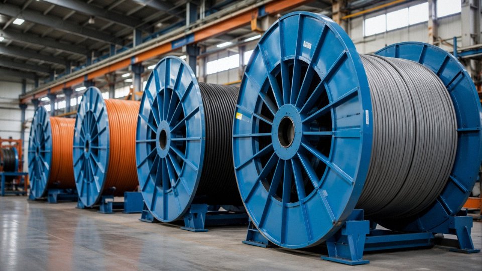
Jinda was established in 1987, which in the Chinese cable industry means it predates the explosive expansion phase that created hundreds of smaller, less stable manufacturers. Over roughly three and a half decades, the company has grown to five manufacturing bases across China, covering around 470,000 m² of production area with over 1,000 employees. For a procurement manager placing a large order, that scale matters in a specific, practical way: it means Jinda can run power cable and control cable production simultaneously without one line cannibalizing capacity from another, and it means raw material purchasing — copper rod, XLPE compound, PVC, armor strip — happens at a volume that reduces exposure to spot-market spikes.
Consistency across a large order is the real test. A plant that’s commissioning a 20-building industrial complex needs all its 0.6/1 kV control cables to come from the same compound batch, with the same insulation wall thickness and the same jacket hardness. Variation between drums causes problems during termination and causes headaches during inspection. At Jinda’s production scale, batch traceability and process control are not optional extras — they’re operational necessities.
Jinda holds ISO 9001 quality management certification and produces cables tested to IEC standards with CCC certification for China Compulsory Certification where applicable.True
These are standard, verifiable certifications for a manufacturer of Jinda's size and export scope; ISO 9001 and IEC compliance documentation are routinely issued with export orders and reviewed by third-party inspectors.
Certifications That Actually Simplify Customs
Export documentation is an underappreciated headache. Cables heading to the Middle East, Southeast Asia, Sub-Saharan Africa, or Europe each carry different import requirements — SASO in Saudi Arabia, SONCAP in Nigeria, CE marking expectations in Europe, and so on. Jinda’s certification portfolio — ISO 9001, IEC test reports, CCC certification, and export compliance documentation — covers a wide enough range that most standard international shipments clear customs without the back-and-forth that plagues smaller suppliers. In practice, having a proper IEC test report for a cable’s voltage class and construction is often the difference between a smooth clearance and a three-week hold at port. Ask for this documentation upfront. Any credible manufacturer should produce it without hesitation.
How the Technical Review Process Works
When a customer sends Jinda a cable schedule — even a rough one, maybe just a spreadsheet listing circuit descriptions, estimated current loads, voltage levels, and environment conditions — Jinda’s engineering team goes through it line by line. They identify where a power cable is needed versus a control cable, flag any specifications that seem inconsistent (an undersized conductor for a stated current, a voltage rating mismatch, a missing shield requirement for a noise-sensitive control circuit), and recommend the correct cable codes under GB or IEC designation systems. This comes back as a formal quotation with full technical datasheets attached.
That process costs the customer nothing and frequently catches errors that would have resulted in a change order on site.
Order Flexibility for Non-Standard Requirements
Standard drum lengths don’t always fit project logistics. Jinda can produce custom drum lengths, accommodate non-standard core counts — say, a 19-core control cable where the catalog stops at 12 — and manufacture special voltage ratings for specific grid environments. Minimum order quantities for international projects are negotiable and depend on the cable type and production complexity; it’s worth a direct conversation rather than assuming the catalog minimums apply.
If you have a cable schedule or project specification ready, contact Jinda’s international sales team for a free technical review and competitive quotation. Send the document as-is — even a draft is enough to start a useful conversation.