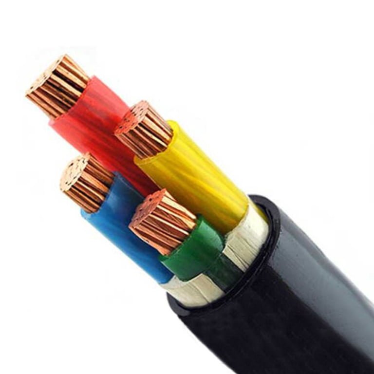
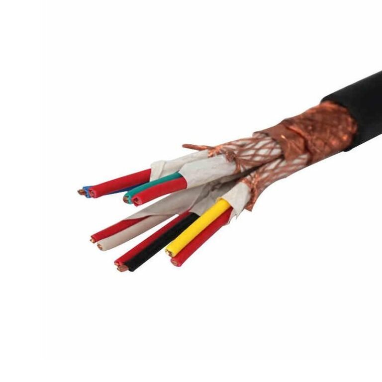
Someone pulls a spool of Cat5e out of the electrical room and starts running it to a sensor panel because it’s what’s on the shelf, it’s cheap, and the conductors look perfectly fine. That decision — made in about thirty seconds — can quietly create an insulation failure, a ground fault, or a fire risk that doesn’t show up until months later under load or heat cycling. By then, the cable is buried in conduit, possibly behind a machine guard, and the rework cost is easily ten to twenty times what proper cable would have run in the first place.
No, Cat5 and Cat5e are not rated for 600V. UL-listed Cat5e is rated for 125V AC, or 150V AC under some standards — full stop. The NEC classifies these as communications cables under Article 800, not power conductors. Running Cat5e on any industrial power circuit that operates above those voltage thresholds violates the listing, voids compliance, and creates a genuine safety hazard regardless of whether the cable “works” in the short term.
What makes this worth digging into is that the question sounds simple but the real-world answer has more layers than most people expect. The conductor gauge, the insulation chemistry, the NEC article that actually governs the cable, and the difference between what a cable can carry briefly versus what it’s listed to handle continuously — all of that matters when you’re making a procurement decision or signing off on an installation. The gap between 125V and 600V isn’t just a number; it reflects a fundamentally different engineering standard.
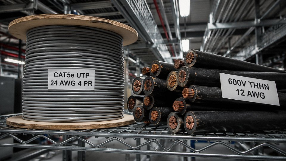
Cat5 Electrical Architecture: AWG 24, Twisted Pairs, and Insulation Designed for Data Signals
Before you can answer the voltage rating question, you have to understand what Cat5 cable actually is at a construction level — because the physical design makes the answer self-evident.
The Conductor: 24 AWG and What It Was Built to Do
Cat5 and Cat5e use 24 AWG bare copper conductors, either solid or stranded depending on whether the cable is for horizontal runs or patch applications. The cross-sectional area is roughly 0.205 mm². To put that in perspective, a standard 12 AWG branch circuit conductor — the minimum you’d pull for a 20A, 120V outlet in a U.S. commercial building — is about 3.31 mm². You’re comparing a thread to a wire.
The 24 AWG conductor was sized for one purpose: maintaining a characteristic impedance of 100 ohms (±15 ohms per TIA-568) across the frequency range that Ethernet signals occupy. Current delivery wasn’t part of the design equation. At 60°C ambient, the continuous current-carrying capacity of a 24 AWG solid copper conductor runs somewhere in the 0.5–0.6 A range — and that figure assumes favorable bundling conditions. Industrial control circuits routinely demand 5, 10, 20 amps or more. The conductor isn’t even in the same conversation.
The Insulation: Optimized for Capacitance, Not Voltage Standoff
Each conductor in a Cat5 cable is insulated with either high-density polyethylene (HDPE) or, in plenum-rated versions, fluorinated ethylene propylene (FEP). The choice of dielectric material is driven almost entirely by signal integrity — specifically, by minimizing capacitance between adjacent conductors so that high-frequency signals don’t attenuate before they reach the far end of a 100-meter run.
HDPE has a dielectric strength of roughly 18–24 MV/m depending on the grade and manufacturing process. On paper that sounds impressive. The problem is insulation wall thickness on a 24 AWG data conductor typically runs only 0.15–0.25 mm. Do the arithmetic: at 0.20 mm wall thickness and 18 MV/m dielectric strength, the theoretical voltage withstand works out to around 3,600V in a perfect, uniform field — but real-world dielectric performance degrades with temperature, mechanical damage, manufacturing variation, and long-term aging. The insulation wall was sized to hit a capacitance target of ≤52 pF/m, not to provide a reliable margin against 600V continuous service. There’s a meaningful difference between a material’s raw dielectric strength and what a finished, installed conductor can actually sustain under production conditions over years of service.
Cat5e insulation is rated for 600V because HDPE has high dielectric strengthFalse
HDPE does have good dielectric strength as a material property, but the insulation wall on a 24 AWG Cat5e conductor is only 0.15–0.25 mm thick — sized for capacitance control, not voltage standoff. The UL listing for Cat5e covers 125V AC (some standards allow 150V AC). It is not rated for 600V continuous service under any governing standard.
The Jacket: Fire Containment, Not Primary Insulation
The outer jacket — PVC on CMR (riser) cable, a low-smoke compound on CMP (plenum) — provides mechanical protection and flame spread resistance. It is not part of the electrical insulation system for power purposes. A point that confuses a lot of people: some Cat5e jackets carry a UL marking that includes “600V” or a dielectric withstand reference. That marking indicates the cable passed a UL production-line dielectric test used to verify manufacturing consistency. It is a quality-verification checkpoint, not a continuous operational voltage rating. The NEC draws a hard line here — Article 800 governs communications cables, Article 310 governs power conductors, and the two systems are not interchangeable on the basis of a jacket marking.
The Twisted-Pair Configuration: EMI Cancellation, Not Phase Isolation
Four twisted pairs sounds like it might provide some isolation between conductors — and in a signals context, it does. Twisting cancels common-mode electromagnetic interference by ensuring that each conductor in a pair sees nearly identical noise pickup, which cancels at the receiver. That’s the entire point of the geometry. It has nothing to do with isolating 600V phase conductors from each other. Spacing, dielectric thickness, and the physical separation required between high-voltage conductors operating at 600V are governed by completely different engineering criteria than the twist rate optimized for a 250 MHz signal channel. Running 600V through a twisted pair would essentially concentrate two live conductors in intimate contact across the full cable length — the opposite of safe conductor separation practice.
Decoding the ‘600V’ Print on Cat5 Jacket: What UL and TIA Standards Actually Say
Walk into enough electrical rooms and you’ll eventually find someone who pulled a spool of Cat5e off the shelf, noticed “600V” printed on the jacket, and concluded the cable was rated for 600-volt service. It’s an understandable reading. The number is right there. But that marking means something entirely different from what it looks like on the surface — and the gap between what it means and what people assume it means has caused real code violations, failed inspections, and in a small number of documented industrial incidents, genuine arc hazards.
What UL 444 Actually Tests
Cat5 and Cat5e cables are listed under UL 444, Standard for Safety for Communications Cables. The standard includes a dielectric voltage-withstand test that applies roughly 2,500V AC for one minute between conductors or between conductors and any shield or braid. That test sounds impressive. It is not an operating voltage rating. It’s a manufacturing quality gate — a way to verify that the insulation wasn’t damaged during extrusion, stranding, or jacketing. Think of it like a hydrostatic pressure test on a pipe fitting rated for 150 psi: you test at three times working pressure to confirm integrity, but nobody interprets that as permission to run the line at 450 psi.
The dielectric withstand test voltage in UL 444 represents the safe operating voltage of Cat5e cable.False
The 2,500V AC dielectric withstand test in UL 444 is a manufacturing quality verification procedure, not an operating voltage rating. The actual UL-listed operating voltage for Category communications cables is 125V AC (some legacy listings show 150V AC).
The actual UL operating voltage for Category communications cables listed under UL 444 is 125V AC — some older or legacy listings carry 150V AC, depending on the specific listing date and product family. That’s it. The “600V” you see on certain older Cat5 spools or some riser-rated CMR cable jackets is either a legacy print convention carried over from older jacket material certification practices or a reference to the jacket’s dielectric test performance. Neither interpretation authorizes the cable for use in a 600V electrical power circuit. Full stop.
TIA/EIA-568 and What It Actually Defines
TIA/EIA-568, the telecommunications industry standard governing horizontal and backbone cabling infrastructure, defines Cat5e as a 100-ohm unshielded twisted-pair medium intended for data network applications. Signal levels in those environments run well below 50V — typically in the range of a few hundred millivolts to low single-digit volts during normal Ethernet operation. TIA-568 does not address power distribution. It never has. The standard explicitly scopes itself to communications applications, and nothing in any revision of TIA-568 certifies or implies suitability for use as a power conductor.
PoE (Power over Ethernet), which does run low-voltage DC through Cat-rated pairs, is governed by IEEE 802.3, not by any expansion of Cat5e’s power-handling designation. Even IEEE 802.3bt Type 4 PoE — the highest standardized PoE class — tops out at 90W delivered at roughly 50V DC. That is a completely different world from 600V power distribution.
NEC Article 800 and the Code Boundary
Under the National Electrical Code, Cat5 and Cat5e are classified as communications cables and fall under Chapter 8, specifically Article 800. This is not a minor categorization detail. NEC Chapter 8 is intentionally written as a standalone chapter, largely exempt from the general wiring methods in Chapters 1 through 7. That exemption exists because communications cables operate at signal levels that don’t pose the same shock or fire hazards as power conductors — not because they’re interchangeable with power wiring.
Power conductors in 600V circuits are governed by NEC Article 310, which mandates specific conductor ampacity tables, insulation temperature ratings, conduit fill calculations, and termination requirements that Cat5 cannot satisfy by any stretch. AWG 24 solid copper — the conductor used in Cat5/Cat5e — carries roughly 0.577A continuous at 60°C under typical conditions. Industrial 600V branch circuits routinely operate at 15A to 30A or higher.
Using Cat5e as a power conductor in a 600V circuit doesn’t just violate Article 310. It almost certainly triggers OSHA 1910.303 enforcement exposure, since that regulation requires electrical equipment and conductors to be used in a manner consistent with their listing and labeling. An AHJ (Authority Having Jurisdiction) finding Cat5 terminated in a 600V panel during inspection will not accept a “the jacket said 600V” explanation.
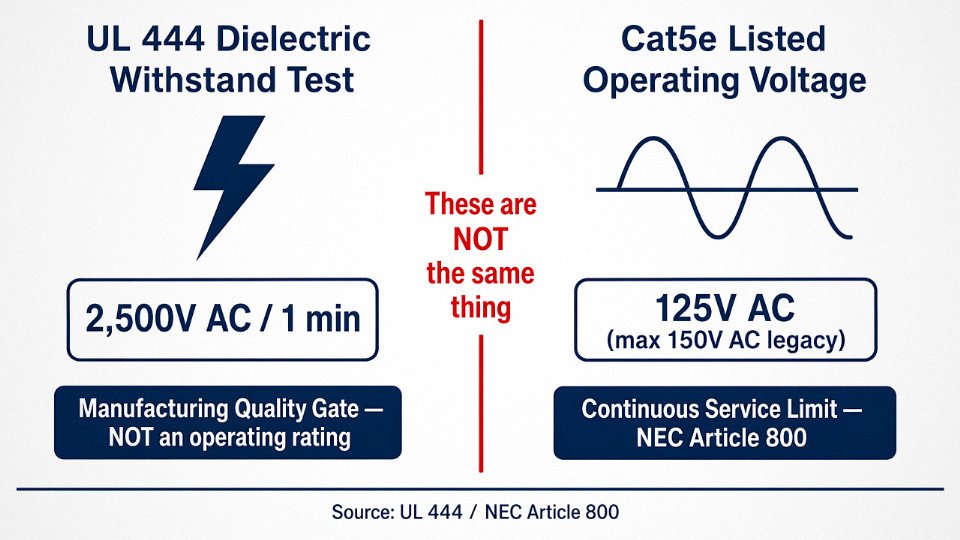
The core takeaway is blunt: the “600V” appearing on a Cat5 jacket is a dielectric test artifact or a legacy print convention. It conveys nothing about the cable’s suitability for power service. It grants zero permission — legally, under UL listing, under NEC, or under any credible engineering standard — to use that cable in a circuit operating at 600V. Anyone making a procurement or installation decision based on that jacket print is working from a fundamental misreading of what the marking actually represents.
Operating Voltage vs. Dielectric Test Voltage vs. Insulation Class: A Field Engineer’s Distinction
These three terms get conflated constantly — even by people who should know better. Understanding the difference matters every time you read a cable jacket marking, not just when someone asks whether Cat5 can run 600V.
Operating Voltage (Rated Voltage)
This is the number that actually governs whether a cable is safe for continuous use in a circuit. Specifically, it’s the maximum continuous RMS voltage — conductor-to-conductor or conductor-to-ground — that the cable is designed, constructed, and listed to carry indefinitely under normal service conditions.
For power cables, IEC 60502 expresses this as Uo/U, where Uo is the conductor-to-ground voltage and U is the conductor-to-conductor voltage. A “0.6/1 kV” cable is rated for 600V to ground and 1,000V between phases. That designation drives real physical design decisions: insulation wall thickness, insulation material selection (XLPE vs. PVC vs. EPR), and the safety margins baked into both. A 0.6/1 kV cable per IEC 60502-1 typically has a minimum insulation wall of 0.7–1.0 mm, depending on conductor cross-section. Cat5 insulation walls are a fraction of that — they’re engineered for signal integrity and crosstalk control, not for sustained electrical stress.
For Cat5e, the operating voltage is 125V AC under UL 444, or 150V AC under some other listings. That’s the number that matters in the field.
Dielectric Withstand (Hipot) Test Voltage
Here’s where the confusion usually starts.
A hipot test is a factory quality-assurance procedure. You apply a much higher voltage — often 2× to 4× the rated operating voltage — across the insulation for a short, controlled duration, typically 60 seconds to 5 minutes. If the insulation doesn’t break down, flash over, or draw excessive leakage current, it passes. The test confirms that there are no manufacturing defects: voids, thin spots, contaminants in the insulation.
Passing a 2,500V hipot test does not mean the cable can operate at 2,500V. It means the insulation survived a brief overstress without failing catastrophically. Continuous operation at elevated voltage is an entirely different physical regime — thermal aging, partial discharge, dielectric fatigue over thousands of hours. A hipot test tells you nothing about that.
A cable that passes a 2,500V hipot test is safe to operate continuously at 2,500V.False
Hipot (dielectric withstand) tests apply elevated voltage briefly to check for manufacturing defects. They do not qualify a cable for continuous operation at the test voltage. Operating voltage is a separate, lower rating governed by insulation design, material, and applicable standards such as UL 444 or IEC 60502.
Insulation Voltage Class and What It Demands Physically
IEC 60502-1 defines low-voltage cables as those up to 1 kV Uo/U. Getting there requires deliberate engineering. XLPE insulation, minimum wall thicknesses, specific conductor stranding, and often bedding or armoring layers. The gap between a data cable and even the bottom rung of the power cable hierarchy is substantial — not a gray area.
| Cable Type | Operating Voltage | Hipot Test Voltage | Min. Insulation Wall (approx.) |
|---|---|---|---|
| Cat5e (UL 444) | 125V AC | ~2,500V | 0.15–0.20 mm |
| THHN 14–10 AWG (UL 83) | 600V | ~2,200V | 0.38–0.51 mm |
| 0.6/1 kV power cable (IEC 60502-1) | 1,000V | ~3,500V | 0.7–1.0 mm |
The table makes the point clearly: higher hipot test voltages don’t cascade into higher operating ratings. Each cable type is designed from the ground up for its operating class.
The Current Problem Compounds Everything
Even if you somehow convinced yourself the insulation would hold — it won’t, but hypothetically — the conductor still fails you. AWG 24 solid copper carries roughly 0.577A continuously at 60°C ambient. A standard 600V, 20A branch circuit requires AWG 12 minimum (about 2.05 mm² cross-section), per NEC Table 310.16. That’s a current capacity gap of roughly 35:1. You get both voltage insulation failure risk and thermal overload simultaneously. One problem would be bad enough.
In practice, the thermal failure usually comes first — the conductor heats, the already-thin insulation softens, and breakdown follows. The sequence is fast and the result is a fire hazard, not just a tripped breaker.
NEC, IEC, and OSHA Compliance Consequences of Using Cat5 in 600V Applications
The technical case against using Cat5 in a 600V circuit is straightforward enough. The regulatory case is where things get genuinely expensive — and where facility managers, not just electricians, need to pay attention.
NEC Article 310.3: Listed for the Application, or It Doesn’t Count
NEC Article 310.3 requires that conductors used in electrical power systems be listed and rated for their specific application and operating voltage. This is not a performance suggestion. A conductor that is not listed for 600V power service cannot legally serve that function, full stop. Cat5 carries a UL listing under UL 444 as a communications cable — that listing covers data signal transmission, not power distribution. The moment you pull Cat5 into a 600V circuit, you have an unlisted installation. It will fail inspection, and the installing contractor is on the hook for the remediation.
In practice, AHJs vary in how aggressively they inspect low-voltage-looking cable in conduit runs, but any inspector who traces a conduit back to a 600V panel and finds Cat5 will issue a rejection. Rework on a completed conduit run in a production facility — reopening walls, pulling new wire, re-terminating — can run anywhere from a few hundred dollars on a short exposed run to tens of thousands on a buried or concrete-encased installation, depending on access and labor rates in your region.
NEC Article 800: Separation from Power Conductors Is Mandatory
There is a second compliance failure that often gets overlooked. NEC Article 800.48 and 800.179 require that communications cables be physically separated from electric light, power, and Class 1 circuit conductors. Running Cat5 in the same conduit as 600V power wiring violates these separation requirements independent of any voltage rating question. So even if someone argues (incorrectly) that the dielectric test voltage on the jacket label covers the application, the co-routing violation is still there. You can fail on two grounds simultaneously.
OSHA 29 CFR 1910.303(b)(1): Where It Becomes a Willful Citation
OSHA’s general industry electrical standard at 29 CFR 1910.303(b)(1) requires that all electrical equipment be installed and used in accordance with its listing and labeling. Using Cat5 cable in a power circuit is a direct violation. OSHA classifies violations as other-than-serious, serious, or willful/repeated — and if an employer was aware of the correct requirements and proceeded anyway (which procurement records, submittal packages, and installer certifications can all prove), the classification moves to willful. Current OSHA penalty schedules allow citations up to roughly $15,625 per violation per day. In a facility with multiple non-compliant runs, those citations stack. A single incident investigation that uncovers systematic misuse of Cat5 in power circuits could generate liability that dwarfs the original cable procurement savings by an order of magnitude.
Using Cat5 cable in a 600V power circuit constitutes a willful OSHA violation under 29 CFR 1910.303(b)(1) when the installer had prior knowledge of listing requirements.True
OSHA 29 CFR 1910.303(b)(1) mandates that electrical equipment be used per its listing and labeling. Cat5 is listed as a communications cable under UL 444, not as a 600V power conductor. Knowingly installing it in a power circuit violates this standard and, where documented awareness exists, OSHA can escalate to willful classification with penalties up to $15,625 per violation per day under current schedules.
IEC 60364-5-52: The International Framework Reaches the Same Conclusion
For facilities operating under IEC standards — common across Europe, the Middle East, and much of Asia — IEC 60364-5-52 governs cable selection based on rated voltage, current-carrying capacity, and installation method. The standard’s cable selection tables require that a cable’s rated voltage meet or exceed the circuit’s operating voltage. Cat5, rated at 125V to 150V AC depending on the applicable standard, cannot satisfy the voltage column requirement for any 600V circuit under any installation method column in that table. There is no workaround, no derating factor, no engineering justification that gets Cat5 over that threshold.
Insurance, AHJ Sign-Off, and What Happens After a Fault
Property and casualty insurers increasingly require NEC or IEC compliance as a condition of coverage for industrial facilities. If a fault occurs and the investigation finds Cat5 in a 600V application, the insurer has a straightforward basis to deny the claim — the installation was non-compliant at the time of the loss. For a manufacturing plant, that denial could mean absorbing the full cost of equipment damage, business interruption, and any third-party property or injury claims out of pocket.
AHJs can and do fail occupancy inspections for exactly this type of deficiency. Depending on jurisdiction and building use, a failed occupancy inspection means the facility cannot legally operate until the deficiency is corrected and re-inspected. In a production environment, that is real downtime measured in production output, not just inspection fees.
The remediation cost, the OSHA exposure, the insurance denial risk, and the potential plant shutdown — none of this is theoretical. It follows directly and predictably from one decision: using a cable in an application it was never listed to serve.
Legitimate Uses of Cat5 in Industrial and Commercial Facilities: Where It Belongs
Cat5 and Cat5e cable have a real and well-defined place in industrial and commercial buildings. The goal here isn’t to rehabilitate a misunderstood product — it’s to give procurement teams and facility engineers a clear-eyed map of where this cable belongs so neither error gets made: using it where it’s dangerous, or pulling it out of applications where it’s perfectly appropriate and cost-effective.
Structured Data Cabling and Horizontal LAN Runs
The bread-and-butter application. TIA-568 defines a permanent link maximum of 90m for horizontal cabling, with up to 10m of patch cord on each end for a 100m channel total. Inside those limits, Cat5e handles 10BASE-T, 100BASE-TX, and 1000BASE-T (Gigabit Ethernet) without issue. In practice, most manufacturing plant offices, control rooms, and warehouse floor data drops fall well within this envelope.
Cat5e remains cost-effective for Gigabit where the cable runs are short and the traffic profile doesn’t justify Cat6 or Cat6A. A lot of engineers reflexively spec Cat6A for everything now, which is fine if budget allows, but for a 30m run to a workstation in a packaging line office, Cat5e does the job. The caveat: if the building is going through a major infrastructure refresh, it’s usually worth the marginal cost difference to go Cat6 from the start. Retrofits are expensive.
Industrial Ethernet Inside Low-Voltage Control Panels
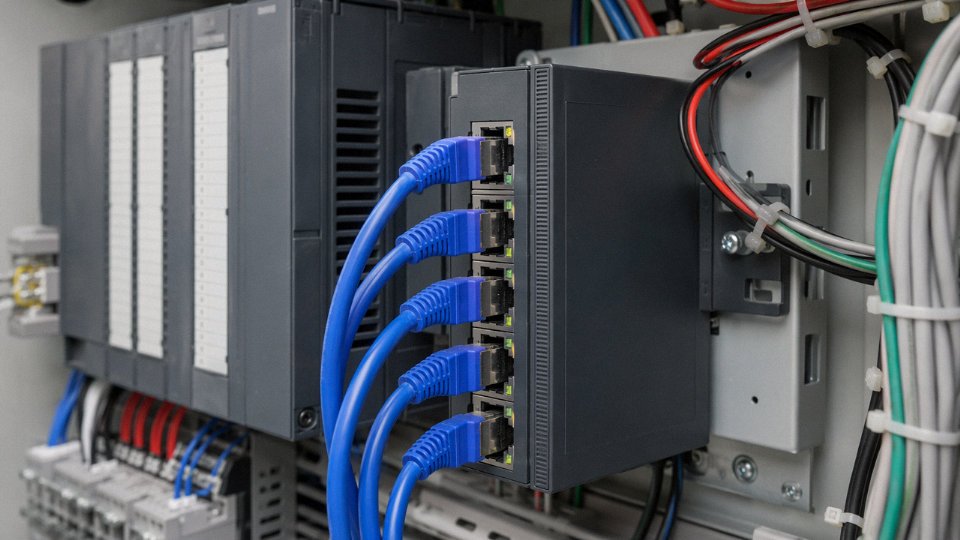
Cat5e patch cables are commonly used inside control cabinets to connect PLCs, HMIs, managed Ethernet switches, and SCADA servers. Voltages in these environments typically stay below 50V DC, well within Cat5e’s rated operating voltage. This is a legitimate, routine application.
That said, NEC Article 800 still requires physical separation from power wiring even inside enclosures. Running a Cat5e patch cable in the same wire bundle as 120V or 24V AC control wiring is a compliance problem — and a signal integrity problem. Keep data cables separated and routed along their own dedicated trunking inside the panel.
Power over Ethernet (PoE) — The Highest Legitimate Power Application
IEEE 802.3af (PoE) delivers up to 15.4W at roughly 44–57V DC open-circuit. IEEE 802.3at (PoE+) pushes that to 30W. Cat5e handles both classifications — the pairs carry both data and low-voltage DC simultaneously, and the cable’s insulation and conductor geometry are designed for exactly this kind of application.
PoE on Cat5e operates at voltages far below 600V and is a legitimate, standard application for this cable type.True
IEEE 802.3af and 802.3at PoE standards operate at 44–57V DC nominal, which is within Cat5e's rated operating voltage. This is categorically different from 600V power circuits and fully compliant with both UL 444 and NEC Article 800.
This is, incidentally, the ceiling. PoE+ at 57V open-circuit is as high as legitimate voltage goes on Cat5e. Anything above that is outside the design envelope.
Building Automation and BACnet/IP Networks
IP-based building automation systems — VAV controllers, smart lighting nodes, BACnet/IP field controllers — are a natural fit. Signal integrity is the design criterion here, not current-carrying capacity, and Cat5e delivers. Runs inside a typical commercial building rarely exceed 60–70m point to point, leaving meaningful margin under the TIA-568 channel limit.
Perimeter Security and IP Camera Infrastructure
Cat5e is widely deployed for IP cameras, both for Ethernet data and PoE power delivery to cameras. Again, PoE voltages only. The camera runs are usually under 80m, and in facilities where someone has specified Cat5e for this work, it performs reliably for years with minimal maintenance overhead.
What Is Explicitly Outside This Cable’s Scope
Motor control circuits. VFD output wiring — where high-frequency switching produces voltage spikes that can punch through inadequate insulation. Any branch circuit operating at 120V, 208V, 240V, 480V, or 600V. Class 1 control wiring above 30V per NEC. Anything requiring conductors rated above 125V AC under UL 444.
These aren’t gray areas or judgment calls. They’re hard boundaries.
Correct Cable Selection for 600V Industrial Applications: Specifications and Standards
Once you’ve confirmed that Cat5 has no business anywhere near a 600V circuit, the next practical question is: what cable do you actually need? The answer depends on your installation environment, conductor count, whether you’re running through conduit or open tray, and whether a variable frequency drive is in the picture. Getting this wrong means failed inspections at minimum — insulation fires and arc flash events at worst.
THHN/THWN-2 — The Workhorse for North American Conduit Runs
THHN/THWN-2, listed under UL 83, is the cable most North American electricians reach for first on any 600V branch circuit or feeder. It’s rated 90°C in dry locations and 75°C in wet, with dual-rated THWN-2 versions covering both. Conductor sizes run from AWG 14 all the way up to 1,000 kcmil, so you can specify it for a 20A lighting circuit or a 400A feeder without changing product families. PVC insulation is standard; cross-linked variants handle slightly more aggressive environments. One practical note: THHN pulls easier through conduit than many alternatives because of its nylon jacket, which matters when you’re fishing 200 feet of #4 AWG through a crowded 2-inch EMT run.
XHHW-2 — Wet Locations and Chemical Environments
Where moisture is a real factor — underground conduit systems, outdoor cable trays, pump stations, food processing areas with regular washdowns — XHHW-2 (UL 44) is usually the better choice. Cross-linked polyethylene insulation gives it meaningfully better resistance to moisture ingress and a wider range of chemical exposure compared to standard PVC. Still rated 600V, still 90°C wet and dry. In my experience, plants that run THHN into wet-location conduit and then wonder why their megger readings drop after a few seasons would have saved themselves real headaches by specifying XHHW-2 from the start.
MC Cable — Mechanical Protection Without Full Conduit
Type MC Cable (UL 1569) is armor-clad, using interlocked aluminum or steel armor over THHN/THWN conductors, 600V rated. It’s used where you need branch circuit flexibility and mechanical protection but full conduit isn’t practical — exposed runs along equipment frames, drops to individual machine tools, connections inside panel enclosures. It does require proper MC fittings; a stripped end stuffed into a knockout without an approved connector is a code violation and a shock hazard.
Type TC-ER — Industrial Tray Systems
In larger industrial plants, Type TC-ER (UL 1277, exposed run rated) handles the tray systems connecting motors, sensors, and control panels. Its real advantage over conduit-based wiring is flexibility in routing and the ability to combine instrumentation pairs with power conductors in a single jacketed assembly, which reduces tray fill and simplifies termination. Rated 600V, available in a wide range of conductor configurations. The “ER” designation matters — without it, tray cable can only run in the tray itself, not the exposed drops off the tray edge.
IEC 60502-1 for International Projects
Outside North America, the reference standard is IEC 60502-1, covering low-voltage power cables rated 0.6/1 kV with XLPE or PVC insulation in copper or aluminum conductor versions. Jinda produces cables to this standard for export across more than 50 countries, in configurations from single-core to multi-core armored assemblies. Voltage designation “0.6/1 kV” means 0.6 kV phase-to-ground and 1 kV phase-to-phase — so the cable is fully appropriate for nominal 600V systems.
Standard Cat5e rated at 125V AC can be used in 600V circuits if only low current is flowing.False
Voltage rating and current rating are independent parameters. Cat5e is limited to 125V AC under UL 444 regardless of how little current flows. Applying 600V to Cat5e insulation risks dielectric breakdown, arcing, and fire — current level is irrelevant to this failure mode.
Shielded VFD Cable — A Separate Category Entirely
Variable frequency drives deserve a specific callout because standard 600V THHN is genuinely insufficient for VFD output circuits. VFDs generate high-frequency switching transients that can reach 1,600V peak on a nominal 480V system, and the capacitive coupling from unshielded conductors causes bearing currents, EMI interference with nearby instrumentation, and premature insulation failure. Dedicated VFD cable uses symmetrical ground conductors and 100% braid or foil-braid shielding, rated 600V–1,000V AC, and is required by most drive manufacturers as a warranty condition. NEC Article 430 also addresses the wiring methods for motor branch circuits, and ignoring the manufacturer’s cable specification voids both the drive warranty and your NEC compliance footing.
Quick Selection Checklist
Before you specify anything for a 600V application, run through these in order:
- Rated voltage (Uo/U) must equal or exceed the circuit operating voltage — no exceptions
- Conductor ampacity at actual installation temperature (derate for conduit fill, ambient, and continuous loads)
- Listing for the specific installation environment: wet, dry, direct burial, cable tray, exposed run
- Flame-spread rating matched to the installation location (CMR, CMX, TC-ER, or per local authority having jurisdiction)
- VFD output circuits: confirm whether shielded VFD-rated cable is required by the drive manufacturer
Choosing the right 600V cable isn’t complicated once you know the variables — but substituting a data cable because it was on the shelf or cheaper on that day’s purchase order creates liability that outlasts any short-term savings by years.
How to Audit Existing Installations: Identifying Misapplied Cat5 in Power Circuits
Legacy facilities are where this problem actually lives. New construction gets checked; it’s the 2003 tenant fit-out or the “temporary” run someone made permanent that causes grief. If you’re walking into a plant with mixed-vintage wiring and patchy as-built drawings, a systematic audit isn’t optional — it’s the only way to know what’s actually in those conduits.
Step 1: Read the Jacket Print Line
Pull any cable you can’t positively identify and hold it under a decent work light. Every UL-listed cable carries sequential footage printing embossed or printed on the jacket at regular intervals — typically every 24 inches or so. A legitimate 600V power conductor will carry markings like 600V THHN, XHHW-2 600V, or on IEC-rated product, 0.6/1 kV IEC 60502-1. Those strings are legally required and unambiguous.
Cat5 and Cat5e jacket printing reads completely differently. You’ll see strings like CAT5E UTP CMR, EIA/TIA-568, CMP (plenum), or the manufacturer’s name followed by a part number — none of which are power-circuit ratings. If you pull a cable out of a conduit feeding a motor starter or a panel sub-feed and it reads CAT5E, flag it and do not re-energize that circuit. Full stop.
In practice, the tricky cases are cables where the jacket has been painted over, abraded, or is simply too dirty to read without cleaning. A rag and some solvent will usually get you to legible print. If the print is genuinely gone, treat the cable as suspect and proceed to the next steps.
Step 2: Measure the Conductor
Strip back roughly an inch of jacket and measure the conductor diameter with a wire gauge tool or digital calipers. Cat5 uses AWG 24 solid copper — 0.511 mm bare conductor diameter. The minimum conductor size for a 600V branch circuit under NEC Article 310 is AWG 14, which measures 1.628 mm. That’s more than three times the diameter. Visually, the difference is stark; a Cat5 conductor looks almost like a thread next to even the smallest legitimate power conductor. You don’t need precision instruments to see it, though confirming with a gauge tool gives you defensible documentation.
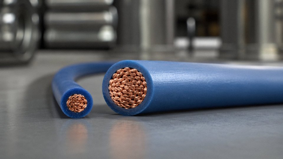
AWG 24 Cat5 conductors are visually and measurably smaller than the minimum AWG 14 required for 600V branch circuits under NEC Article 310.True
AWG 14 has a bare conductor diameter of approximately 1.628 mm; AWG 24 measures approximately 0.511 mm — a difference easily confirmed with basic calipers or a wire gauge card.
Step 3: Thermal Imaging Under Load
If the circuit is currently energized and you can safely observe it before de-energizing, a thermal camera is revealing. Cat5 misapplied in a power circuit will show concentrated heat at termination points — panelboard lugs, terminal strips, junction box connections — because AWG 24 copper simply can’t dissipate the resistive heating at any meaningful load current. Elevated temperatures of 20–50°C above adjacent conductors are typical, depending on load. Some installations run for months before thermal runaway at a lug causes a fire or a breaker trip. Don’t assume the absence of a trip means the installation is acceptable.
Step 4: Megohmmeter Testing
A 500V or 1,000V megohmmeter test on a de-energized circuit will usually confirm the diagnosis. Cat5’s thin polyethylene or FEP insulation — designed for signal integrity at low voltages, not for high-potential stress — commonly shows insulation resistance below 1 MΩ when tested at 1,000V DC. Properly rated 600V THHN will typically show hundreds of megohms or more on the same test. Low IR readings at this test voltage are a hard disqualifier for power service.
Documentation and Remediation
Log every finding with photographs, cable type from jacket print, conductor gauge measurement, circuit breaker ID, and panel location. De-energize immediately. Replace with correctly rated conductors before re-energizing — not after. Notify the Authority Having Jurisdiction (AHJ) if the installation previously passed inspection; that conversation is uncomfortable but legally necessary. Update as-built drawings with the corrected installation, and keep the photographic record for at least as long as your facility’s liability exposure period requires. One well-documented audit packet has, in more than a few cases, been the difference between a correctable finding and a serious insurance or OSHA enforcement outcome.
Frequently Asked Questions About Cat5 Voltage Ratings and Cable Compliance
Can I use Cat5 for low-voltage 12V or 24V DC power?
Technically, Cat5’s 125V AC listing exceeds 12V or 24V DC, so the insulation itself won’t fail from voltage stress at those levels. That part is fine. The problem is the conductor. AWG 24 solid copper carries roughly 0.5–0.6A continuous before you start accumulating heat at terminations and along the run — and that ceiling drops further with bundling or elevated ambient temperature. At 12V, even a modest 3W load draws 250 mA, which sounds comfortable until you factor in a 15-meter run and measure the actual voltage at the device end. Voltage drop on AWG 24 over any meaningful distance at 12V or 24V DC is punishing; you can easily lose 10–15% of supply voltage before you’ve even reached mid-run. For anything powering a sensor, a relay coil, or a control panel accessory, that matters. Use stranded DC power cable sized for the actual load and run length — 18 AWG or 16 AWG stranded is a far more appropriate starting point for most light industrial 24V DC circuits. Cat5 in this role is a tempting shortcut that tends to surface as a frustrating intermittent fault six months later.
Does the ‘600V’ on the Cat5 jacket mean it passed a 600V test?
The '600V' marking printed on a Cat5 or Cat5e cable jacket indicates the cable is rated for 600V operating service.False
Under UL 444, Cat5/Cat5e is listed at 125V AC operating voltage. The '600V' marking that sometimes appears on communications cable jackets refers to dielectric withstand test voltage or appears as part of a riser/plenum classification print line — not as an operating voltage rating. These are fundamentally different parameters.
This is probably the single most persistent misreading in the field. The UL 444 listed operating voltage for Cat5 and Cat5e is 125V AC. Full stop. Any reference to a higher voltage figure on the jacket relates to a dielectric withstand test — a short-duration proof test applied during manufacturing quality control, not a continuous service rating. Confusing test voltage with operating voltage is an easy mistake, but it’s a consequential one.
Can Cat5 be run in the same conduit as 480V power wiring?
No. NEC Article 800.133(A)(1)(b) requires physical separation between communications cables and electric light or power conductors. Running Cat5 in the same conduit as 480V wiring is a code violation regardless of what the Cat5 insulation can theoretically withstand. Beyond the code issue, inductive coupling from power conductors into unshielded twisted pairs at that voltage level will corrupt any data signal you’re trying to pass — so it fails on practical grounds too, not just regulatory ones.
What is the maximum voltage Cat5 cable can safely carry?
125V AC under its UL 444 listing. Exceeding that voids the listing, puts you outside NEC Article 310 compliance for any power application, and creates a genuine insulation failure risk under sustained overvoltage. There is no safe margin above 125V AC for continuous service — the cable simply isn’t architected for power duty.
Is Cat6 or Cat6A rated for 600V?
No, and this surprises people. Cat6, Cat6A, even Cat7 and Cat8 — all governed by UL 444 or IEC 61156 as communications cables, all carrying similar 125V AC operating voltage limitations. A higher category number means better high-frequency performance, tighter pair geometry, stricter crosstalk specs. It says nothing about power handling capability. The conductor gauge on Cat6 is still AWG 23 or AWG 24. The insulation wall is still optimized for signal integrity, not dielectric strength under power-circuit conditions.
What cable should I use for a 600V motor circuit in a factory?
For North American installations, THHN/THWN-2 in conduit (UL 83, rated 600V) is the standard workhorse for branch circuits and motor feeders. XHHW-2 is the better choice for wet locations or outdoor conduit runs where moisture ingress is realistic. For international projects — particularly facilities in Europe, the Middle East, or Southeast Asia working under IEC frameworks — IEC 60502-1 XLPE-insulated armored cable is the appropriate specification. Conductor sizing, armor type, and sheath material all depend on installation method, ambient temperature, fault current levels, and local utility requirements. Jinda Special Cable Group manufactures a full range of low-voltage power cables to IEC 60502-1 for exactly these global industrial applications, with project-specific engineering support available.
What happens if Cat5 insulation is exposed to 600V?
The insulation wall on a Cat5 conductor — typically 0.15–0.25 mm of HDPE or FEP depending on jacket type — is not designed to hold off 600V continuous service. Under those conditions, dielectric breakdown between adjacent conductors becomes a realistic failure mode, not a theoretical one. What follows is arc-over between pairs, carbonization of the insulation, and a potential ignition source inside whatever conduit or cable tray the cable is routed through. Personnel shock hazard is real if the cable is accessible. In practice the failure may not be immediate — it can take weeks or months of thermal cycling and micro-degradation before the insulation gives — which is precisely what makes this dangerous. The installation looks fine right up until it doesn’t.
Why Specifying the Right Cable From a Qualified Manufacturer Protects Your Project
Cable specification errors rarely announce themselves at the design stage. They announce themselves at 2 a.m., when a production line trips offline and the maintenance crew starts tracing the fault back to an insulation breakdown that nobody expected for another decade.
The Real Cost of Getting It Wrong
A misspecified cable in a 600V industrial circuit doesn’t usually fail catastrophically on day one. What typically happens is slower and more expensive: thermal cycling degrades the undersized insulation over months, partial discharge activity begins at stress points, and eventually you get an insulation-to-ground fault that trips a breaker — or worse, starts a fire. Remediation in an active industrial facility means pulling cable through conduit that’s now fully occupied, re-terminating panels, potentially repainting or repairing cable trays that show heat damage, and all of this while the line is down.
Unplanned downtime in manufacturing environments runs roughly $100,000 to $400,000 per hour depending on industry sector, production volume, and whether the failure cascades into adjacent systems. The Aberdeen Group’s industrial downtime benchmarks have pegged average figures around $260,000 per hour across discrete and process manufacturing. Even at the low end of that range, a single eight-hour outage to rewire a section of panel because someone substituted Cat5 for a rated control cable costs more than the entire cable budget for a mid-sized project, several times over.
The incremental cost of specifying correctly rated 600V cable — say, a THHN/THWN-2 control cable or a properly rated multicore instrumentation cable — over a data cable of equivalent physical dimensions is negligible. We’re talking about pennies per meter in most cases. The risk premium simply isn’t worth it.
What to Actually Verify in Manufacturer Documentation
Procurement managers under schedule pressure sometimes accept a datasheet and a price. That’s understandable, but it’s where specification drift happens. For any cable going into a 600V-class industrial application, the documentation checklist should include:
- UL listing number and UL CCAI (Category Code) — confirms the cable type and the rated voltage recognized under UL’s listing, not just the manufacturer’s marketing claim
- IEC 60502-1 test reports for projects outside North America, or for any international supply chain where IEC governs the installation standard
- Factory hipot test certificates for each production batch, not just a type-test certificate from years ago
- Third-party witnessed routine test reports when the project risk level or client specification requires it
- RoHS and REACH compliance documentation — increasingly a procurement requirement even for purely industrial cables, especially for projects in the EU or for OEM equipment exported globally
A manufacturer who can’t produce these documents quickly, or who offers substitute certificates that don’t match the delivered product’s construction, is a procurement risk regardless of price.
Jinda’s Manufacturing and Quality Infrastructure
Shandong Jinda Special Cable Group operates five production bases in China with approximately 470,000 m² of manufacturing spaceTrue
This figure is stated in the company's official profile and represents consolidated manufacturing capacity across all production sites.
Jinda’s integrated quality system runs from raw material incoming inspection through in-process production testing to finished goods routine electrical tests — conductor resistance per IEC 60228, voltage withstand per IEC 60502-1, insulation resistance, and where applicable, partial discharge testing. That’s not a paper system; it’s tested on every production batch. The R&D laboratory supports product development against IEC, UL, AS/NZS, and BS standards, which matters when a project specification calls for a standard the average trading company has never heard of.
Serving customers in more than 50 countries since 1987 means Jinda’s documentation infrastructure has been stress-tested by third-party audits, end-client inspections, and the kind of procurement scrutiny that comes with large international EPC projects. The production capacity is there to support bulk supply schedules without compromising batch-level test documentation.
Engage the Manufacturer Before the Cable Schedule Is Locked
The most expensive point to discover a specification problem is during installation. The least expensive point is during the design phase, before the cable schedule is issued for procurement. Engineers and procurement managers specifying cables for 600V or higher applications — power feeders, motor circuits, control wiring, instrumentation loops — should engage a manufacturer with demonstrated standards expertise early enough to review the cable schedule against the applicable installation standard, flag any conflicts, and confirm that every cable type on the project is correctly rated, tested, and documented.
That conversation costs nothing. The alternative can cost considerably more.