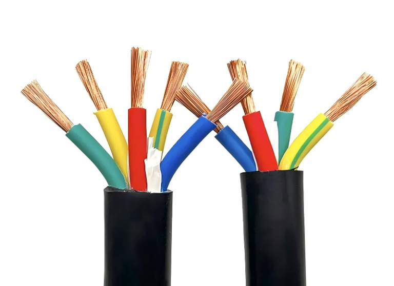
When a control signal misfires because the wrong cable is carrying both power and low-level instrumentation in the same trunking, the fault rarely announces itself cleanly. You get intermittent trips, ghost alarms, or a VFD that throws nuisance faults on humid mornings and runs fine by afternoon. Chasing that kind of noise can burn a week of technician time before someone pulls the wiring schedule and realizes the cable spec was wrong from the procurement stage — and by then, you’ve already got unplanned downtime, a frustrated maintenance crew, and a plant manager asking questions nobody wants to answer.
A power control cable is a multi-core cable designed to simultaneously carry both power supply and control signals to electrical equipment — typically rated between 450/750 V and 0.6/1 kV for low-voltage applications, with conductor sizes most commonly ranging from 0.5 mm² to 10 mm². It combines flexible routing, mechanical protection, and electrical screening in a single run, making it the standard choice for machine tools, automation panels, motors, and switchgear installations.
What makes this cable type genuinely interesting — and genuinely easy to get wrong — is that the word “control” in the name is doing a lot of work. The construction, the core count, the shielding arrangement, and the insulation material all shift depending on whether you’re feeding a 24 V relay circuit, a 690 V motor starter, or a PLC output card that’s intolerant of any noise floor above a few millivolts. The gap between a cable that technically passes and one that actually performs is where most procurement mistakes live.
Anatomy of a Power Control Cable: Every Layer and Its Engineering Role
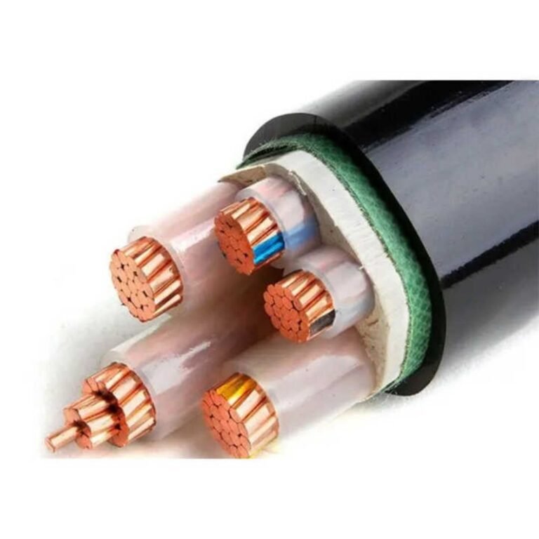
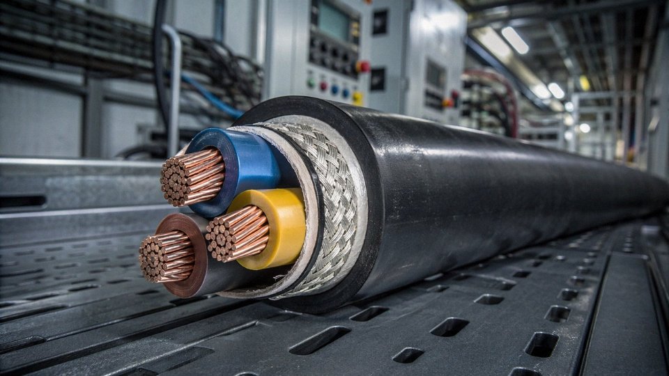
Pull apart a well-made power control cable and you’ll find five to eight distinct layers, each engineered to solve a specific problem. Skipping a layer in the specification — or substituting a cheaper material — rarely shows up on day one. It shows up at month eighteen, usually during a summer heat peak or after a wet season, and by then you’re looking at unplanned downtime and a finger-pointing exercise between the cable supplier and the panel builder.
Conductor Material and Stranding
The conductor is almost always annealed plain copper. IEC 60228 defines Class 1 (solid) for fixed installations where vibration is absent and termination is straightforward, and Class 2 (stranded) for the vast majority of panel wiring where the cable gets routed around corners and re-terminated more than once over its life. In practice, Class 2 is what most procurement orders specify — 7-strand for smaller cross-sections like 1.5 mm², 19-strand for 4 mm² and above.
Tinned copper matters more than people give it credit for. In humid coastal plants, food-processing environments where cleaning chemicals mist onto cable trays, or anywhere the ambient chlorine level is meaningful, plain copper oxidizes at the strand surfaces and termination resistance creeps upward over years. Tinning adds roughly 8–12% to conductor cost depending on tin market conditions, but it’s cheap insurance against a failing control signal five years from now.
Strand count also affects how easily a ferrule or compression lug seats cleanly. More strands, more surface area, less risk of individual wires folding outside a Phoenix or Weidmüller terminal block during termination. In tight DIN-rail panels, that matters.
Insulation Compounds
Three compounds dominate:
| Compound | Max Continuous Temp | Dielectric Strength | Typical Use Case |
|---|---|---|---|
| PVC (general grade) | 70 °C | 10–15 kV/mm | Standard indoor panels, dry environments |
| XLPE | 90 °C | 18–25 kV/mm | Higher load duty, moisture-exposed runs |
| EPR | 90 °C (some grades 110 °C) | 15–20 kV/mm | Low-temperature flex, mining, outdoor |
XLPE’s cross-linked structure resists moisture ingress and thermal deformation under sustained load better than PVC. EPR is the right call for installations where the cable flexes repeatedly at temperatures below −25 °C — a freezer tunnel or an outdoor northern-climate installation — because PVC goes brittle and cracks at the bends.
Core Identification
Beyond five cores, color-coding alone becomes impractical. IEC 60446 governs the standard color sequence (brown, black, grey, blue, green-yellow for earth), but for 12-core or 19-core cables, ink-jet sequential number printing on the insulation surface is standard. The print legibility after years of service depends heavily on ink adhesion to the insulation compound — something worth checking in a factory sample before committing to a bulk order. A misread core in a 19-core cable during a panel retrofit can mean a day lost to fault-finding.
Inner Assembly Geometry
Cores are twisted in pairs or triads and then laid concentrically in layers. The lay length — typically 8 to 16 times the pitch diameter, depending on cable class — directly affects capacitance balance between cores and EMI susceptibility. Tighter lay lengths reduce capacitive imbalance, which matters in analog 4–20 mA loops running alongside switched loads. Loose lay in a cheap cable isn’t always obvious until you see signal noise on a PLC input card.
Shielding Options
Shielding selection depends on the noise frequency you’re defending against and the attenuation you need:
- Individual pair foil shields work well for high-frequency interference above roughly 100 kHz, common near variable-frequency drives. Each pair gets its own drain wire.
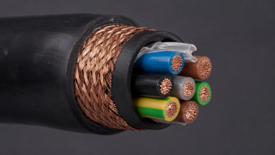
- Overall tinned copper braid at 85–95% optical coverage handles lower-frequency interference and provides a lower-impedance ground path. It’s the workhorse choice for general industrial control environments.
- Foil-plus-braid combination is the belt-and-suspenders option for installations near high-power switchgear or in cement or steel plants where the electromagnetic environment is genuinely harsh. Expect 20–30% more cable diameter and price premium, but the attenuation improvement in the 1–100 MHz range can be 15–25 dB better than braid alone, depending on construction quality.
An overall braid shield at 85–95% optical coverage provides meaningful EMI attenuation for typical industrial control frequencies.True
Optical coverage at this level is the standard specification for industrial screened control cables per IEC and CENELEC standards, and the attenuation performance at common VFD switching frequencies (2–16 kHz) is well-documented in cable manufacturer technical data.
Inner and Outer Sheaths
The inner sheath binds the cabled cores before armoring or the outer sheath goes on. The outer sheath is where the application environment drives the decision hard:
- PVC ST2 covers the majority of standard industrial and commercial installations. Oxygen index around 28–32%.
- LSZH (Low Smoke Zero Halogen) is mandatory in tunnels, metro rail, data centers, and public buildings where evacuation time matters. Oxygen index typically above 30–34%, and smoke density is dramatically lower than PVC in a fire scenario. It costs more and is slightly stiffer to route.
- PUR (polyurethane) is the correct choice for drag-chain applications — machine tools, robotic arms, automated storage systems — where the cable flexes millions of cycles. PVC fatigues and cracks. PUR doesn’t, usually surviving 5–10 million flex cycles in properly sized cable carriers.
Armoring Layer
Steel wire armoring (SWA) is the standard for direct-burial runs and anywhere mechanical impact is a real risk — cable trenches in a manufacturing yard, runs across a loading dock. For single-core cables, SWA is the wrong call: the steel creates a closed magnetic loop that generates eddy current heating under AC load. Aluminum wire armoring (AWA) is what you specify for single-core medium-voltage applications. Steel tape armoring is a lower-cost option where the threat is rodent damage rather than impact — agricultural installations, grain handling facilities — because the tape provides puncture resistance without the weight and cost of full wire armor.
Getting these layer decisions right before the bill of materials is locked saves rework. Getting them wrong is how a cable specified for a panel environment ends up failing in a direct-burial run two winters later.
IEC, GB, and Other Global Standards That Govern Power Control Cable Specification
Getting the standard wrong on a procurement order is not a minor paperwork issue. Cables rejected at customs, failing third-party inspection on a plant commissioning audit, or substituted with a non-equivalent specification can stall a project by weeks and trigger penalty clauses. Here is a working reference for the standards that actually matter on international control cable projects.
IEC 60502-1 and IEC 60502-2
IEC 60502 is the dominant international benchmark for extruded solid dielectric power and control cables. Part 1 covers cables rated up to and including 1 kV — which takes in the bulk of industrial control cable procurement — while Part 2 steps up to the 6 kV–30 kV range relevant to medium-voltage switchgear control circuits.
Mandatory type tests under Part 1 include conductor DC resistance (verified against IEC 60228 class tolerances), insulation resistance measured at 20°C after immersion, AC voltage withstand applied core-to-core and core-to-screen, a bending test around a mandrel sized to cable diameter, and thermal aging of insulation samples at elevated temperature — typically 100°C or 135°C depending on compound — for 168 hours minimum. Partial discharge testing applies once you move into Part 2 territory.
One thing that catches procurement teams off guard: IEC 60502-1 does not mandate a specific core color sequence for cables above five cores. That discretion sits with the manufacturer or the national annex.
GB/T 9330 and Where It Diverges
China’s GB/T 9330 covers plastic-insulated control cables and is broadly harmonized with IEC 60502 in test methodology, but diverges in a few practically significant ways. Core color assignment in GB/T 9330 follows a defined sequence using black numbering on a colored base for cores above five — a detail that matters when you are wiring into Chinese-made control panels that technicians expect to read by color convention. Insulation thickness tolerances in GB/T 9330 are marginally tighter on the lower bound for the 0.5 mm²–1.5 mm² range, which can affect whether a cable produced to the minimum IEC wall thickness passes Chinese market inspection. Not a dramatic difference, but enough to cause a rejection if the cable was optimized to IEC minimums and then submitted for GB compliance testing.
NEMA WC 57 / ICEA S-73-532 for North America
North American projects use AWG conductor sizing notation rather than mm², which means a “14 AWG” control cable and a “2.5 mm²” control cable are close but not identical — 2.5 mm² is actually 13 AWG equivalent in cross-section. Substituting one for the other on a UL-listed panel build can void the panel listing. Insulation designations under ICEA S-73-532 use alphanumeric type codes (XHHW, THW) that do not map directly onto IEC insulation designations. Flame testing follows UL 1685 vertical tray protocol, which is a different specimen geometry and burn duration than IEC 60332-3. A cable certified to IEC 60332-3-24 is not automatically equivalent for a UL vertical tray listing — this is a common and expensive assumption.
BS 6346, BS EN 50525, and Post-Brexit UK Conformity
BS 6346 — the older UK steel-wire-armored cable standard — has largely been superseded in new designs by the harmonized BS EN 50525 series, which aligns UK designations with CENELEC HD 361 harmonic designations. For imported control cables entering the UK market post-Brexit, CE marking alone is no longer sufficient. UK Conformity Assessed (UKCA) marking is required for Great Britain (England, Scotland, Wales), though Northern Ireland retains CE route access under the Windsor Framework. The HAR mark, issued by national testing bodies within CENELEC member states, remains recognized in Great Britain for certain cable categories under a transitional arrangement — but verify current OPSS guidance before specifying it on a project, because the transitional window has been extended more than once and the status genuinely shifts.
CPR Euroclass Fire Ratings
The EU Construction Products Regulation imposes Euroclass fire performance declarations on cables installed in construction works. Eca is the baseline — essentially a single-cable vertical flame test. Dca adds heat release and flame spread criteria suitable for general industrial buildings. Cca requires low smoke opacity and limited lateral flame spread, making it appropriate for schools, hospitals, and commercial buildings. Bca and the highest class, Aca (reserved for inherently non-combustible materials), demand significantly more rigorous fire performance.
Achieving Cca or higher is a compound formulation problem, not an afterthought. It typically requires LSZH (low-smoke zero-halogen) or specially flame-retarded PVC compounds with verified limiting oxygen index values, plus construction geometry that limits flame propagation path.
A cable with IEC 60332-3 flame retardancy certification automatically qualifies for CPR Euroclass Cca.False
IEC 60332-3 and CPR Euroclass Cca test different performance parameters under different test regimes. A cable must be tested and declared specifically under EN 50575 / EN 13501-6 to carry a Euroclass Dca or Cca designation. IEC flame retardancy test results cannot be directly substituted.
Third-Party Certifications: Marine, Hazardous Areas, and Panels
DNV and ABS type approval is required for control cables used in marine vessel electrical systems — both classification societies have their own cable test programs and approved product lists, and “equivalent to marine grade” is not a phrase that holds up during a flag state inspection. For hazardous-area installations, ATEX certification (EU Directive 2014/34/EU) or IECEx certification (international scheme) applies to cables used in zones classified as explosive atmosphere locations. UL 508A governs industrial control panel wiring in North America; cables used inside listed panels must come from UL-recognized manufacturers with the specific cable type recognized.
Multi-Standard Production at Jinda
Running a single cable design through multiple standard certifications simultaneously requires deliberate process control rather than post-production testing luck. Jinda’s production planning aligns raw material specifications — conductor class, insulation compound LOI values, sheath thickness tolerances — to the most demanding parameter across the applicable standards in a given project batch. That approach means a cable produced for an IEC project can typically carry GB/T 9330 compliance without a separate production run, which matters when a project spans a Chinese domestic segment and an international export segment under the same contract.
Voltage, Current, and Core Count Selection: A Practical Sizing Guide
Getting the voltage class wrong is rarely catastrophic on day one. It shows up six months later as insulation breakdown, nuisance tripping, or a ground fault that takes a shift to diagnose. So this deserves more thought than copying the previous project’s spec.
Voltage Class Selection Logic
The 450/750 V rating is appropriate for protected indoor wiring — inside a panel enclosure, inside a trunking system that keeps the cable away from mechanical abuse. The moment a cable exits the panel and runs across a cable tray, through conduit exposed to foot traffic, or alongside anything that could pinch or abrade it, step up to 0.6/1 kV. That extra insulation wall costs maybe 8–15% more per meter (depending on conductor count and insulation material), which is trivial against the cost of pulling a replacement cable.
The Um (maximum system voltage) margin principle is straightforward in practice: the cable’s rated voltage must be chosen so that Um — the highest voltage that can appear between any conductor and ground under normal operating conditions — sits comfortably below the insulation’s design ceiling. For a 6 kV nominal system, Um typically reaches 7.2 kV. That rules out 3.6/6 kV class cable immediately; you need 6/10 kV. Mining operations and utility substations running medium-voltage motor control circuits get this wrong more often than you’d expect, usually because someone applied the low-voltage procurement habit to a medium-voltage job.
Current-Carrying Capacity and Derating
IEC 60364-5-52 gives you the baseline ampacity tables, but the installation method determines which column you’re actually allowed to use. Method B (cables in conduit on a wall) runs roughly 15–20% lower than method E (clipped direct in free air), and method D (direct buried, 0.7 m depth, standard soil) sits somewhere between the two depending on soil thermal resistivity — a value most procurement specs never bother to define, which is a mistake when you’re burying cable in sandy desert soil versus damp clay.
A worked example that comes up constantly: a 10-core 2.5 mm² Cu/PVC/PVC control cable, method B installation, 40 °C ambient. Base ampacity from IEC 60364-5-52 Table B.52.5 for 2.5 mm² in conduit is roughly 18–19 A per core (depending on insulation type). Temperature correction factor for 40 °C with PVC insulation is approximately 0.87. Grouping factor for 10 cores in one conduit — you’re looking at 0.50–0.58 depending on arrangement. So derated capacity per core lands around 8–9 A. That’s significantly below what a naive reading of the conductor size would suggest.
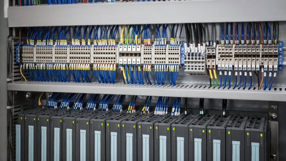
A 10-core 2.5 mm² cable in a conduit at 40 °C ambient can be derated to as low as 8–9 A per core under IEC 60364-5-52 grouping and temperature correction.True
IEC 60364-5-52 method B base ampacity for 2.5 mm² PVC is approximately 18–19 A; applying a 0.87 temperature correction factor (40 °C, PVC) and a grouping factor of 0.50–0.58 for 10 loaded cores in conduit yields roughly 8–9 A, well below the uncorrected value.
Voltage Drop in Control Circuits
This is where engineers who work primarily on power systems get tripped up. A 5% voltage drop on a 400 V motor feeder is 20 V — the motor doesn’t care. A 5% drop on a 24 V DC control loop is 1.2 V. Relay coil dropout voltages are typically specified at 80% of nominal, meaning your coil needs at least 19.2 V to guarantee pickup. Lose 1.2 V in the cable and you’re sitting at 22.8 V at the coil — fine in summer, marginal when the coil winding is cold and resistance has shifted slightly.
The formula is simple: V_drop = I × R × L, where R is conductor resistance in Ω/m (round-trip, so multiply single-conductor resistance by 2 for a two-wire run) and L is run length in meters. For a 50-meter 24 V DC circuit using 1.5 mm² copper conductors, R is roughly 0.0245 Ω/m round trip. At 100 mA steady-state draw: V_drop = 0.1 × 0.0245 × 50 = 0.12 V. Fine. But a solenoid valve on the same run pulling 500 mA inrush for 20–30 ms? That’s 0.61 V drop at the instant of energization — still within margin here, but on a longer run or a thinner conductor it bites you, particularly when three or four valves energize simultaneously during a machine sequence.
Keep 24 V DC control circuit voltage drop below 2–3% for reliable relay and solenoid operation. For 110 V AC control circuits the tolerance is more relaxed, typically 5–7% acceptable, but verify coil dropout spec on every device regardless.
Core Count Planning and Segregation
The ISA-5.1 practice of reserving 10–20% spare cores is worth following literally. In practice, a 7-core cable with one spare is marginal — you’ll use it within a year. A 19-core cable with three or four spares is more realistic for anything that might expand. Spare cores should be individually identified and terminated to the earth bar at one end; leaving them floating inside a multi-core cable creates capacitive coupling problems on long runs.
Segregation matters more than most panel designers admit. Running 230 V AC power cores alongside 24 V DC PLC input signals in the same cable jacket is technically permissible under some standards but produces induced noise on the DC side that manifests as spurious input toggling — the kind of fault that takes a day to reproduce and another day to chase. If the cable run is under 10 meters and well-shielded, you can usually get away with it. Beyond that, split into separate cables. The extra cost of a second cable is always less than the commissioning time lost diagnosing ghost signals.
Conductor Cross-Section vs. Mechanical Requirements
IEC 60204-1 sets the floor at 1.5 mm² for field wiring subject to vibration — motor junction boxes, conveyor drives, anywhere the cable flexes cyclically or gets transmitted vibration from a machine frame. The 0.5 mm² minimum is only legitimate inside a protected panel enclosure where the conductor is supported in terminals and never moves. Specifying 0.5 mm² for field wiring to save money is a short-term decision that leads to strand breakage failures at the terminal crimp, usually 18–36 months into service.
| Application | Minimum Cross-Section | Voltage Class | Notes |
|---|---|---|---|
| Internal panel wiring, static | 0.5 mm² | 450/750 V | Supported, no vibration |
| Panel wiring, some flex | 1.0 mm² | 450/750 V | Control circuits, hinged doors |
| Field wiring, vibration present | 1.5 mm² | 0.6/1 kV | IEC 60204-1 minimum |
| Long field runs, voltage drop sensitive | 2.5 mm² | 0.6/1 kV | Most common industrial spec |
| Medium-voltage motor control | 2.5–6 mm² | 3.6/6 kV or 6/10 kV | Per Um and ampacity calculation |
Special Load Types
Solenoid valves have inrush-to-holding current ratios of 6:1 to 10:1 depending on the valve design and voltage class — this is the number to use when evaluating whether multiple simultaneous actuations will cause a voltage drop excursion that affects other devices on the same circuit. Capacitive loading on long cable runs (anything over 100–150 meters for typical multi-core constructions) can look like a leakage fault to PLC input cards with sensitive input impedance. Some older card designs see that capacitive current and latch a false input high. The fix is either a lower-capacitance cable construction or a series resistor on the input, but catching this in the cable selection stage is far cheaper than an engineering change order after installation.
Size for transient loads, not just steady-state. The IEC 60364-5-52 tables give you the thermal limit. The application gives you the actual current profile. Use both.
Key Industrial Applications: Where Power Control Cables Are Actually Installed
The cable gets specified differently depending on where it lives. A 7-core 1.5 mm² screened cable that works perfectly in a clean automation panel would be wholly inadequate running through a gas compression skid or a longwall mining section. Understanding the installation environment — not just the voltage and current — is what separates a sound cable selection from an expensive failure.
Oil and Gas Upstream and Midstream
Wellhead control panels and ESD valve actuator wiring are where specification errors cause the most visible damage. These circuits carry both 24 V DC control signals and low-current solenoid supply, often in the same sheath, which is exactly the power-control hybrid function the product is designed for. In Zone 1 and Zone 2 classified areas, you’re typically looking at flame-retardant XLPE insulation with steel wire armoring (SWA) and an LSZH oversheath — the armoring handles mechanical protection in cable trays routed along pipe racks, and the LSZH outer sheath limits smoke and toxic gas release if a fire does propagate. ATEX certification isn’t optional here; a substitution with a standard PVC-sheathed cable to close a procurement gap has caused project hold-ups at final inspection more than once.
Electric Power Generation and Substation Automation
In a high-voltage switchyard, EMI levels are severe enough to corrupt unscreened control signals between protection relays, marshalling kiosks, and bay control units. Screened twisted-pair multicore control cables — often with an overall aluminum-polyester foil plus drain wire — are essentially mandatory rather than just recommended. Cable tray fill ratios matter here too; most protection engineers work to around 40–50% fill by cross-section to allow heat dissipation and leave room for future circuits, though the exact figure depends on ambient temperature and whether the tray is in direct sun on a rooftop gantry.
Manufacturing and Automotive Assembly
PLC I/O runs to distributed I/O stations can stretch 30–100 m across a large assembly cell, and in that environment you’re managing voltage drop on 24 V DC, noise pickup from variable frequency drives on adjacent routes, and the practical question of how often the cable gets disturbed during retooling. For robotic arms and moving axis applications, flexible drag-chain cables need to be rated for bending cycles — anything under 5 million cycles is usually undersized for a production robot running two shifts. Some servo installations combine power and encoder feedback in a single hybrid cable; it simplifies routing but means the whole run needs replacing if either function fails.
Mining and Tunneling
Long cable routes in underground roadways impose armoring requirements, and trailing cables for continuous miners have to tolerate being repeatedly dragged across rock surfaces. Flame-retardant and antistatic properties aren’t negotiable — IEC 62913 sets a baseline, and most national mining regulators layer additional requirements on top. Getting this wrong isn’t a performance issue; it’s a safety incident.
Marine and Offshore Platforms
IMO SOLAS fire safety requirements push virtually all offshore control cable toward halogen-free, flame-retardant construction. Mud resistance in subsea riser applications is a separate concern from fire performance. What tends to get underestimated is vibration — 25 years of ship hull vibration works termination connections loose, so cable designs with robust screen bonding and mechanical stability at the gland matter as much as the cable construction itself.
Building Automation and Infrastructure
Elevator machine rooms, HVAC control panels, and fire system auxiliary circuits look straightforward, but EU projects now have to match CPR Euroclass requirements that directly dictate the flame performance class of the cable sheath. A procurement team sourcing from outside the EU occasionally lands product that meets IEC 60332 flame tests but doesn’t carry the required CE marking and CPR classification — which causes rejection on handover.
Renewable Energy
Wind turbine tower cables carry torsion loads from nacelle rotation that standard cables aren’t designed to handle; the conductor stranding and insulation compound both need to accommodate millions of twist cycles over the turbine’s life. Solar farm combiner box wiring runs in direct burial or UV-exposed conduit, which shifts the outer sheath requirement toward UV-stabilized compound. BESS control interconnects are a growing application — typically 2–4 core cables at 0.6/1 kV with a drain wire screen — where the main engineering concern is managing ground loops between battery management systems and plant SCADA.
Flame-retardant XLPE insulation with SWA armoring and LSZH oversheath is the standard construction for power control cables installed in ATEX Zone 1 oil and gas environmentsTrue
This construction combination directly addresses the three primary hazard requirements in Zone 1: flame propagation resistance (XLPE and LSZH), mechanical protection in industrial cable trays (SWA), and reduced toxic smoke emission under fire conditions (LSZH oversheath), all consistent with IEC 60079 series and EN 60332 requirements applied in ATEX-certified installations.
EMI Shielding Performance and Signal Integrity in Noisy Industrial Environments
Plant electrical environments are genuinely hostile to signal integrity. A modern manufacturing floor running a dozen variable frequency drives, arc welders, and a wireless mesh network is, electrically speaking, a broadband noise generator — and your control cable runs right through the middle of it.
Where the Noise Actually Comes From
VFDs are the dominant offender in most industrial facilities. Their IGBT switching stages generate steep dV/dt transients — often 5–10 kV/µs on the DC bus — that couple capacitively onto adjacent cables and radiate conducted interference across a frequency band roughly spanning 150 kHz to 30 MHz. Arc welding equipment produces lower-frequency burst noise, typically concentrated below 1 MHz but with significant harmonic content up to 10 MHz. High-current busbars radiate magnetic fields at 50/60 Hz and their harmonics, which matter less for RF shielding but cause common-mode current problems on long analog runs. Wireless access points and RFID readers operating at 900 MHz, 2.4 GHz, and 5.8 GHz sit above the range where conventional cable shielding is effective — at those frequencies, physical separation and panel filtering carry more weight than the cable shield itself.
The practical consequence: a 4–20 mA analog signal on a PLC input has a full-scale range of 16 mA. A noise floor of even 0.5 mA represents roughly 3% error. In temperature or pressure control loops, that shows up as hunting, false alarms, or subtle process drift that takes weeks to diagnose.
How Foil Shields Work — and Where They Fall Short
An aluminum-polyester foil wrapped around the cable cores creates a near-complete Faraday enclosure. Current induced by an external field circulates in the foil and is dissipated rather than transmitted to the conductors inside. The drain wire — a bare or tinned copper conductor running in contact with the foil — provides the low-impedance return path that makes this work. Without a drain wire bonded at the grounding point, the foil’s shielding effectiveness drops sharply because the induced currents have nowhere useful to go.
Transfer impedance (Z_T, measured in mΩ/m) is the correct metric for quantifying shield performance. A well-made foil shield achieves 5–15 mΩ/m at low frequencies, which sounds impressive. The problem is that foil shields are thin — typically 25–50 µm — and above roughly 10 MHz, skin depth effects and foil discontinuities at the longitudinal seam allow field penetration. Foil alone above 10 MHz is largely decorative from a shielding standpoint.
Braid Shields: Optical Coverage Is Not a Marketing Spec
Braid shielding performance depends critically on optical coverage — the percentage of the underlying surface actually covered by the braid wires. This is not interchangeable. A 65% coverage braid provides roughly 20 dB of attenuation at 1 MHz. A 95% coverage braid gets you into the 40–50 dB range at the same frequency — a factor-of-ten difference in noise voltage reaching your PLC input. For a 12-bit analog input with a 10 V span, 20 dB versus 40 dB attenuation can mean the difference between ±5 mV noise and ±50 mV noise at the terminal.
A 95% optical coverage braid shield provides approximately 40–50 dB attenuation at 1 MHz compared to roughly 20 dB for a 65% braid.True
Braid shielding attenuation scales with optical coverage due to reduced aperture size for field penetration; these ranges are consistent with IEC 62153-4 series transfer impedance measurements published by multiple cable metrology laboratories.
Procurement teams sometimes specify “braid shielded” without stating coverage percentage. Suppliers will meet that spec with a 65% braid. Get the coverage number in writing.
Foil-Plus-Braid: When the Cost Premium Is Justified
Combined foil-and-braid construction adds 15–30% to cable unit cost depending on conductor count and braid wire gauge. That premium is worth it in three specific situations: drives rated above roughly 90 kW where switching transients are severe; cable runs exceeding 100 m routed in the same cable tray as VFD output power cables; and installations where cable tray separation is constrained by existing plant infrastructure and you cannot achieve the routing margins described below. In those cases, the combination shield provides broadband coverage — the foil handles mid-frequency interference and the braid closes the gap above 10 MHz — resulting in transfer impedance below 5 mΩ/m across the full 150 kHz–30 MHz band.
Grounding the Shield: The Detail That Undoes Everything
Single-point grounding — connecting the drain wire at one end only, typically the control panel end — is correct for low-frequency interference below roughly 1 MHz. It prevents circulating ground currents that would otherwise inject 50/60 Hz noise directly into the signal circuit. Multi-point grounding (bonding the shield at both ends, and at intermediate junction boxes) is necessary for high-frequency immunity above 1 MHz, because a ground-referenced shield needs very short current return paths to be effective at short wavelengths.
The most common mistake on the plant floor is floating both ends — the installer didn’t connect the drain wire at all, or connected it only to a floating cable tray. This nullifies shielding effectiveness almost entirely. In practice, I’ve seen plants spend money on premium foil-braid cable and then lose most of the benefit because the drain wire was left unconnected in the field junction box.
Routing and Separation Rules
IEC 61000-5-2 defines cable segregation classes based on signal level and susceptibility. The practical takeaway for installation: maintain at least 200 mm of physical separation between power cables (especially VFD output cables) and control cables running in parallel. For unavoidable crossings, route at 90 degrees — perpendicular crossing minimizes the coupled length to essentially zero. Parallel runs in shared trays with less than 100 mm separation, even with well-specified shielded cable, frequently produce enough coupled interference to cause intermittent PLC faults that are maddening to diagnose after installation is complete.
These routing rules cost nothing at design stage. They cost a great deal during a retrofit.
Installation Best Practices: Pulling, Bending, Terminating, and Protecting Power Control Cables
Getting the cable specification right and then damaging it during installation is more common than most project engineers want to admit. A crushed insulation layer from a tight conduit bend or a shield that was never properly grounded at the gland — these failures don’t show up immediately. They show up six months later as intermittent trips, ground faults, or noise complaints that take weeks to trace.
Minimum Bending Radius
IEC 60502-1 sets the floor: 12× the overall cable diameter for armored cables, 6× for unarmored. For a 25 mm OD steel wire armored (SWA) cable, that means a minimum bend radius of 300 mm. In practice, cable tray bends and conduit elbows at that diameter should be laid out before installation starts, not improvised on site. Flexible PUR-sheathed cables in drag chains are a different animal — manufacturers typically specify 7.5× to 10× for dynamic applications, and you should confirm the specific figure from the datasheet because it depends on the number of flex cycles, not just the geometry.
Violating bend radius on a multi-core cable doesn’t always cause immediate failure. What it does is work-harden the conductors at the bend point and crack the insulation locally, leaving a latent defect that fails under thermal cycling. On armored cables specifically, over-bending can also distort the armor lay and create a stress riser directly over the inner bedding.
Pulling Tension and Sidewall Pressure
A quick working formula for maximum pulling tension on copper conductors: T (N) = n × A (mm²) × 50, where n is the number of conductors and A is the cross-section of each. A 7-core × 2.5 mm² cable gives a limit of roughly 875 N — not a large number, and easy to exceed with a long conduit run or a sticky lubricant job. Sidewall pressure at bends is the other constraint: keep it below 3,000 N/m for standard cables. Exceeding either limit compresses the insulation under the conductors at the bend, and that compression is permanent. The cable will pass a post-installation IR test and fail within a year.
Use a pulling grip rated for the cable OD, apply manufacturer-recommended lubricant (not grease, not soap — cable-specific compound), and monitor tension with a dynamometer on runs over roughly 50 m or where there are multiple bends.
Cable Tray Fill
NEC 392.22 and IEC 61537 both converge on the same practical limit: don’t exceed about 50% of the tray’s usable cross-sectional area for multi-conductor cables. Calculate fill using the sum-of-areas method — add up the actual cross-sectional area (π/4 × OD²) of every cable in the tray. The error most panel builders make is calculating fill at commissioning and not leaving headroom for the cables that get added during the first plant expansion. Design to 40% if the application allows it.
Gland and Termination Selection
Single compression glands work for unarmored cables; double compression glands are required for SWA cables to grip both the sheath and the armor independently. For screened cables where EMC performance matters, use EMC cable glands with a 360-degree metallic backshell that contacts the braid or foil around its full circumference — pigtail connections to screen drain wires defeat the purpose of the shield almost entirely.
A pigtail screen termination maintains equivalent EMC shielding performance to a 360-degree EMC cable gland.False
A pigtail introduces inductance at the termination point, breaking the continuous shield coverage and significantly degrading high-frequency noise rejection. 360-degree gland contact maintains the Faraday cage effect through the termination.
Torque the gland to the manufacturer’s specified value — under-torquing loses IP rating, over-torquing cracks the sealing ring. Both failures are invisible until water or dust finds the path.
Sealing and Environmental Protection
During storage and before final termination, fit heat-shrink end caps on every cut end. Multi-core cables with hygroscopic filler or paper bedding will wick moisture along their length by capillary action — especially on vertical runs — and a cable that tests fine in the yard can arrive at the termination panel with wet insulation. Cold-applied self-amalgamating tape works for temporary field splices, but it is not a substitute for a proper jointing kit on any circuit that matters.
Labeling and Documentation
In my experience, poor documentation causes more diagnostic downtime than poor cable selection does. Every cable needs a unique identifier at both ends, ferruled conductor numbering matching the loop drawing, and an as-built record that links cable number to source, destination, and core allocation. IEC 62491 gives the labeling framework; the discipline to follow it is a site management issue, not a cable issue. A mislabeled 12-core cable in a motor control center can consume an entire maintenance shift to trace.
Post-Installation Testing
Before energizing, run an insulation resistance test at 500 V DC for 450/750 V rated cables — the IEC 60364-6 minimum is 100 MΩ, and a new cable on a clean installation should read considerably higher, typically several hundred MΩ or more. Low readings at this stage mean a damaged sheath or a nick in the insulation, both of which are easier to find and fix before the tray is closed up. Check conductor continuity across every core and verify shield continuity end-to-end with a low-resistance ohmmeter. If the shield reads more than a few ohms, the armor or braid has a break — find it before commissioning.
Comparing Power Control Cable Types: A Specification Decision Matrix
Specifying “a power control cable” on a bill of materials is not enough. Two cables that both meet that description can behave completely differently in service — one lasting 25 years in a petrochemical trench, another failing in 18 months on a drag chain. The five axes below are where the real decisions live.
Insulation Type: Temperature, Chemistry, and Cost Trade-offs
PVC insulation is the workhorse — cheap, widely available, and perfectly adequate for most indoor panel and conduit runs where ambient temperature stays below roughly 70 °C. XLPE raises the continuous rating to around 90 °C and handles most hydrocarbon vapors far better; it’s the default choice for outdoor industrial runs and medium-voltage control cables above 1 kV. EPR (ethylene propylene rubber) is the right call in wet environments or anywhere with ozone exposure — offshore platforms and water treatment plants, typically — though it costs noticeably more and sourcing lead times can surprise procurement teams. Silicone is a niche product, reserved for furnace surrounds, exhaust-adjacent wiring, and applications that see 150–180 °C continuously; the material cost is several times PVC, and the mechanical fragility means you treat it carefully during installation.
| Insulation | Max. continuous temp. | Chemical resistance | Relative cost | Typical environment |
|---|---|---|---|---|
| PVC | 70 °C | Moderate | Baseline (1×) | Indoor panels, conduit, dry control rooms |
| XLPE | 90 °C (up to 105 °C for special grades) | Good (HCs, dilute acids) | 1.2–1.5× PVC | Outdoor trays, MV control, variable by grade |
| EPR | 90 °C | Excellent (water, ozone) | 1.8–2.5× PVC | Marine, water/wastewater, offshore |
| Silicone | 150–180 °C | Poor (oils, solvents) | 4–7× PVC | Furnaces, exhaust zones, high-heat enclosures |
Sheathing: Smoke, Halogens, and What Happens at -20 °C
Standard PVC sheathing is fine in open industrial facilities. In tunnels, metro stations, data centers, or anywhere personnel can’t evacuate quickly, LSZH (low-smoke zero-halogen) sheathing is the specification you’ll see mandated — and for good reason. PVC burning in an enclosed space produces hydrogen chloride gas and dense black smoke; LSZH compounds produce a fraction of that smoke density and no halogen acid gases. The trade-off is cold-temperature flexibility: standard LSZH compounds can crack on a cold morning (below roughly -5 °C to -15 °C depending on formulation) if you pull them before letting the cable warm up. A mild operational warning here — in northern climates, leaving a reel outdoors overnight before a winter pull is a common way to crack a LSZH outer sheath before the cable even reaches the tray.
PUR (polyurethane) sheathing is genuinely excellent for flexible applications — drag chains, robotic arms, anything with continuous mechanical movement. It handles abrasion, cutting oils, and repeated flexing better than anything else in the standard lineup, but it costs a meaningful premium over PVC. CSP (chlorosulfonated polyethylene, sold under trade names like Hypalon) is the choice for oil-immersion risk and UV-intense outdoor environments, particularly in chemical plants and refineries where hose-down with petroleum solvents is routine.
| Sheathing | Smoke density | Halogen-free | Flex at -20 °C | Oil resistance |
|---|---|---|---|---|
| Standard PVC | High | No | Moderate | Low-moderate |
| LSZH | Very low | Yes | Poor–moderate (grade-dependent) | Low |
| PUR | Low | Usually yes | Good to excellent | Good |
| CSP | Moderate | No | Moderate | Excellent |
Armoring: Mechanical Protection vs. Weight and Pull Tension
Unarmored cable belongs in conduit, cable trays with no mechanical hazard, and inside panels. The moment you’re direct-burying without a duct, running through a concrete trough with foot traffic above it, or pulling through a route where third-party excavation is a real risk, you need armor.
Steel tape armored (STA) gives you reasonable crush protection for direct burial and is lighter than wire armors. Steel wire armored (SWA) handles tensile stress during long vertical runs or pulls over significant distance — it’s the standard for buried power control cables in infrastructure projects. Aluminum wire armored (AWA) trades some mechanical strength for substantial weight savings, which matters on cable trays with load limits and in offshore installations where every kilogram has a cost. AWA also avoids induced eddy current losses in single-core runs better than steel, though for control cables this is rarely the dominant factor.
| Armor type | Crush protection | Tensile protection | Relative weight | Best installation method |
|---|---|---|---|---|
| Unarmored (UA) | None | None | Baseline | Conduit, tray, indoor panels |
| Steel tape (STA) | Good | Low | 1.2–1.5× UA | Direct burial (low tensile demand) |
| Steel wire (SWA) | Good | Excellent | 1.4–1.8× UA | Direct burial, vertical runs, long pulls |
| Aluminum wire (AWA) | Moderate | Good | ~1.2–1.3× UA | Tray-heavy layouts, offshore, weight-sensitive |
Shielding Configuration: EMI Attenuation vs. Price
Unscreened cables work where the environment is electrically quiet and your control signals have enough noise margin. In most real industrial facilities — variable frequency drives, large motor starters, welding equipment nearby — that assumption fails quickly. An overall braid shield offers 85–95% optical coverage and meaningful attenuation across a broad frequency range; it’s the most common upgrade from unscreened and adds roughly 15–30% to cable cost depending on conductor count. Individually screened pairs (each pair wrapped in foil, with a drain wire) are the specification for mixed-signal cables where crosstalk between circuits matters as much as external EMI — common in process automation where a 4–20 mA loop and a digital signal share the same cable. Foil-plus-braid overall is the belt-and-suspenders approach, highest attenuation, highest price, and worth it in genuinely severe EMI environments like the cable tray immediately above a VFD output.
An overall braid shield alone provides sufficient EMI protection in all industrial environments.False
Braid shields are effective for general industrial EMI reduction but individually screened pairs or foil-plus-braid constructions are needed when circuits within the same cable must be isolated from each other or when operating within severe EMI zones such as near VFD output cables or large induction furnaces.
Reading and Writing Cable Designation Strings
Procurement teams working across regions regularly encounter designation strings that look like a foreign language — because in a functional sense, they are. Two common ones worth decoding side by side:
KVVP2-22 3×2.5 (GB standard, China)
– K = control cable
– VV = PVC insulation / PVC sheath
– P2 = copper tape (foil) shield
– 22 = steel tape armor
– 3×2.5 = 3 cores, 2.5 mm² each
NYCY 7×2.5/2.5 0.6/1 kV (European, roughly VDE-influenced)
– N = standard industrial cable
– Y = PVC insulation
– C = concentric conductor (screen/return conductor)
– Y = PVC outer sheath
– 7×2.5/2.5 = 7 insulated cores at 2.5 mm² plus a concentric conductor at 2.5 mm²
– 0.6/1 kV = voltage class
The concentric conductor in the European designation is doing double duty as a shield and a return path — a detail that gets missed when procurement teams substitute one cable for another across standards without reading the construction carefully. Getting this wrong in the field typically means a grounding deficiency in the control circuit, which shows up as intermittent signal faults that take days to trace.
Understanding both systems — and being able to write a specification that maps one to the other — is practical insurance against substitution errors when a project sources from multiple regions or when a tender response comes back with a different national standard than the one specified.
Quality Assurance and Factory Testing Protocols for Power Control Cables
A cable can meet every line item on a datasheet and still fail in the field — usually because someone skipped a test that seemed redundant, or accepted a third-party test report that was six years old and covered a different conductor cross-section. Understanding what rigorous factory testing actually involves helps buyers separate genuine manufacturing discipline from paperwork compliance.
Routine Tests: What Happens to Every Reel Before It Ships
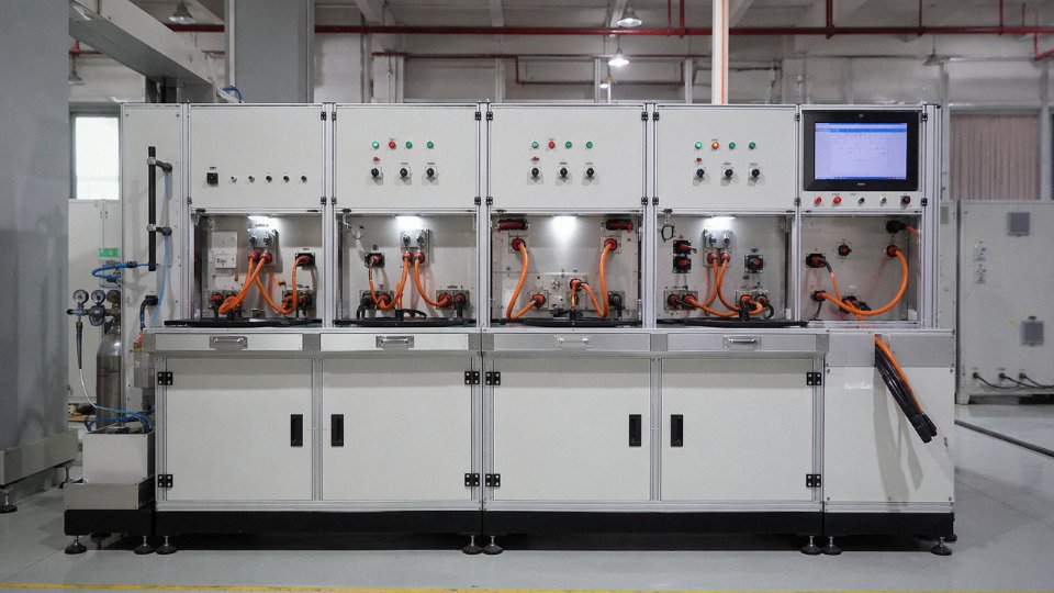
Every finished reel leaving a serious cable plant goes through a fixed battery of routine tests, no exceptions. Conductor DC resistance is measured per IEC 60228 and cross-checked against the declared conductor class — a 1.5 mm² Class 5 stranded conductor has a maximum resistance of 13.3 Ω/km at 20 °C, and anything above that means either undersized wire or a stranding defect. The test sounds simple, but production-line temperature variation, wire draw inconsistencies, and compound errors across 61-core constructions make it easy to drift outside tolerance without noticing.
The AC high-voltage withstand test for 0.6/1 kV cables typically applies 3.5 kV between conductors and between conductor and screen or armor for five minutes. No flashover, no breakdown. For medium-voltage variants this voltage steps up substantially. Insulation resistance is measured separately with a DC megger — values below roughly 100 MΩ·km at room temperature warrant investigation, though the exact threshold depends on insulation material and ambient humidity on the test floor. Visual dimensional inspection confirms overall diameter, insulation wall thickness, and jacket concentricity against the drawing.
Type Tests: Proving the Design Itself Is Sound
Type tests are performed on a cable design, not every reel. They validate the construction against its intended service life. The bending test cycles a sample around a mandrel of specified diameter — relevant because cables routed through cable trays or conduit during installation routinely see bending radii that stress the insulation core interface. Tensile strength and elongation of PVC insulation must meet a minimum 125% elongation at break; aged samples after thermal conditioning must still hit that mark, because PVC that has lost plasticizer gets brittle fast in unheated cable ducts in northern climates during winter.
Thermal aging runs samples in a forced-air oven at 100 °C for seven days, then retests mechanical properties. The numbers should not fall off a cliff. For XLPE insulation the hot-set test is the critical crosslink quality check: a loaded sample held at 200 °C must not exceed 175% elongation under load, and on removal must recover almost fully. A cable that passes the hot-set test has been properly crosslinked; one that fails almost certainly had inadequate peroxide dose or cure time — a production shortcut you will not detect any other way.
Sample Tests and Dimensional Verification
Conductor stranding inspection, insulation eccentricity measurement, and the jacket strip-force test are performed on samples taken at defined intervals rather than every reel. Insulation eccentricity — the variation in wall thickness around a single conductor — should stay within about 10% of nominal wall thickness. Exceed that and you create localized thin spots that concentrate electrical stress. The strip-force test on the jacket-to-armor interface matters more than people expect: a jacket that pulls off too easily means poor adhesion and a water ingress path at termination points.
Flame, Smoke, and Toxicity Testing
IEC 60332-1 covers a single cable mounted vertically and exposed to a defined flame. If the char propagates more than 540 mm above the flame, the cable fails. IEC 60332-3-24 Category C is harder — it tests a full bundled installation of cables carrying a specified volume of non-metallic material, and the test conditions are considerably more severe because bundled cables in a cable tray create their own fuel load.
LSZH power control cables tested to IEC 61034-2 must achieve a minimum light transmittance of greater than 60% in the smoke density chamber test.True
IEC 61034-2 specifies the smoke density test for low smoke cables; a minimum 60% light transmittance is the standard pass criterion confirming low smoke emission during a fire scenario.
For halogen-free cables, IEC 60754-1 limits hydrogen chloride equivalent acid gas emission to a maximum of 0.5% by mass. In an enclosed substation or data center, this is not a box-checking exercise — corrosive combustion gases from burning PVC cables have destroyed operational equipment in adjacent rooms well after the fire itself was contained.
Third-Party Witness Testing and Factory Audits
Major EPC contractors on international projects — particularly in the oil and gas, power generation, and infrastructure sectors — typically arrange witness testing through Lloyd’s Register, Bureau Veritas, or SGS. The third-party inspector attends the factory during production, witnesses the routine and type tests on the contracted batch, and signs the test report. A witnessed test report is worth considerably more than a manufacturer self-certification, and experienced procurement managers know to specify it in the purchase order, not as an afterthought after production has already started.
A complete test report for a witnessed inspection should include: cable type and construction drawing reference, reel numbers and drum lengths, actual measured values (not just pass/fail ticks), equipment calibration certificate numbers, and the inspector’s name and signature. Jinda’s production facilities are set up to accommodate third-party witness schedules for export orders, including providing advance notice of production start dates so inspectors can plan travel — a practical detail that sounds minor until a project deadline slips because a witness visit was not coordinated in time.
Drum Marking, End Protection, and Sea Freight Readiness
Finished reels are marked per IEC 60456 requirements: cable type designation, voltage rating, conductor cross-section and core count, length, reel number, and manufacturer details. Cable ends are sealed — typically with heat-shrink end caps — to prevent moisture ingress during transit. For projects shipping to tropical destination ports with high ambient humidity and extended customs dwell times, a moisture barrier wrap under the outer lagging is not optional. Wooden drum staves must meet fumigation treatment requirements (ISPM 15) for most international destinations, and reel structural strength needs to be adequate for the stacking loads during container shipping. A reel that arrives with a collapsed flange or water-damaged ends wastes everyone’s time and, depending on contract terms, creates a dispute nobody wanted.
How to Evaluate and Select a Reliable Power Control Cable Manufacturer for Large Projects
Choosing a cable supplier for a major project is not a catalog exercise. A wrong call here ripples through commissioning schedules, import documentation, and — if a batch fails insulation resistance after installation — through very expensive rework. The evaluation framework below reflects what experienced procurement managers actually check, not what a brochure says they should.
Production Capacity and Real Lead Time
Quoted price is easy to compare. Actual production capacity is harder to verify and matters far more on a project with a firm commissioning date.
Ask for the manufacturer’s production capacity certificate and look for figures expressed in km per year broken down by conductor size and cable type — not a single aggregate number. A plant running 300 km/year of 1.5 mm² four-core cable may have a completely separate bottleneck for 10 mm² 19-core armored cable. Cross-reference those figures against the delivery schedule you’re being offered. If a supplier is quoting 8-week delivery on 50,000 m of a specialized XLPE-insulated shielded cable while also serving several other large projects, ask how that production slot is reserved. Get it in writing as a capacity allocation, not just a sales commitment.
Seasonal effects matter too. Plants in northern China typically front-load production before Lunar New Year; orders placed in December for February delivery carry real schedule risk unless the material is already in progress.
Raw Material Traceability
A cable is only as good as its copper and its compound. For large projects, demand batch-level traceability, not just a generic material declaration.
Copper rod should come from an LME-registered smelter, and the supplier should be able to produce the mill certificate for each rod coil used in your order — tied to the cable drum serial numbers. PVC and XLPE compounds need incoming batch test certificates showing elongation, tensile strength, and (for XLPE) the crosslink degree. A serious manufacturer retains these records for the full project duration plus a warranty period, typically five to ten years depending on the contract. If a supplier cannot produce these on request during an audit, that is a meaningful red flag.
Jinda maintains full batch traceability for copper rod and insulation compound tied to individual drum serial numbers across all production bases.True
Integrated manufacturing with an in-house R&D and QA infrastructure covering five production bases supports end-to-end material traceability, which is standard practice for suppliers operating across 50+ country markets with varying documentation requirements.
Multi-Standard Certification and Single-Source Advantage
Projects serving multiple export markets — say, a plant being built in Southeast Asia with European-sourced equipment and financing from a Middle Eastern development bank — may require cables certified to IEC, GB, and in some cases UL or CSA simultaneously. Sourcing from two or three suppliers to cover different standards adds coordination overhead, increases the risk of incompatible termination dimensions, and complicates incoming inspection. A manufacturer certified and actively producing to multiple standards under one roof eliminates most of that friction. Verify the scope of each certificate; some manufacturers hold IEC certification for a narrow product range and quietly substitute on items outside that scope.
Technical Support: Trading Company vs. Manufacturer
This distinction matters operationally. A trading company can move paper. A manufacturer can assign a factory engineer to review your conduit fill schedule, confirm derating factors for a specific ambient temperature and grouping configuration, and issue a formal technical deviation letter if your project’s installation conditions push against the cable’s rated parameters. That kind of support is not available from a reseller. On large projects, ask specifically whether the technical contact is employed by the factory and whether they can provide a stamped technical response document — useful if a third-party inspector questions the cable selection.
After-Sales Support and Warranty
A meaningful warranty distinguishes manufacturing defects — insulation voids, incorrect conductor cross-section, failed sheath adhesion — from damage caused by incorrect installation or cable abuse on site. Expect coverage for a defined service life period, usually two to five years post-delivery for manufacturing defects, with clear exclusions. Response time for technical queries should be specified; 48 hours for an initial technical response is a reasonable baseline for international projects. Having a regional technical contact — not just a head-office email — makes escalation practical when a problem surfaces at 6 a.m. on a commissioning day.
Jinda’s Position in This Framework
Jinda has supplied cable to projects in more than 50 countries from five dedicated production bases covering 470,000 m² of manufacturing space, with a product range running from 0.6/1 kV low-voltage control cables through 500 kV power cables. The integrated R&D centre supports multi-standard production — IEC, GB, and project-specific variants — and dedicated international project teams provide documentation in English formatted for any jurisdiction’s import and inspection requirements. That breadth means a single procurement relationship can cover most of a project’s cable scope without the coordination risk of splitting supply across multiple vendors.
Due-Diligence Checklist for Buyers
| Check item | What to verify | Acceptable threshold |
|---|---|---|
| ISO 9001 certificate | Scope covers the cable types you’re ordering | Current, unambiguous scope |
| Factory audit report | Age of most recent third-party audit | Less than 12 months old |
| Material traceability | Batch certificates linkable to drum serials | Available within 48 hours of request |
| Reference projects | Third-party verifiable project names and contacts | At least two verifiable in your region |
| Non-conformance process | Defined escalation path, response time commitment | Written, in the supply agreement |
| Technical contact | Factory-employed engineer, not sales | Named individual, direct contact |
Run through this list during the supplier qualification stage, not after the purchase order is issued. By the time material is on the water, your leverage to fix a documentation gap is essentially gone.
Frequently Asked Questions About Power Control Cables
What is the difference between a power cable and a power control cable?
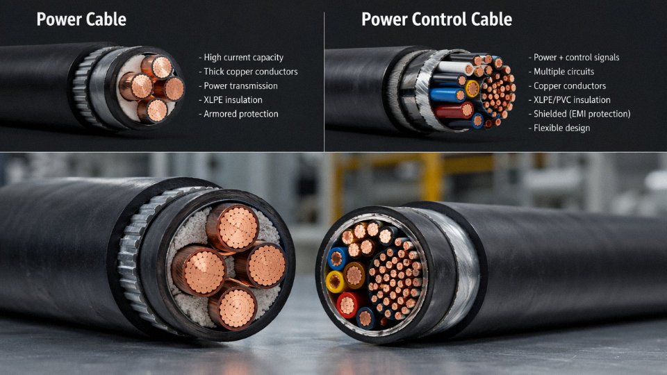
A power cable is purpose-built to carry bulk electrical energy — think motor feeders, transformer secondary runs, or bus risers — at its full rated voltage and current continuously. That’s its only job. A power control cable does something more layered: it combines auxiliary power distribution (usually at 0.6/1 kV or below) with multiple smaller control conductors inside a single common sheath. The practical result is fewer cable trays, fewer termination schedules, and a cleaner panel layout. On a mid-sized process skid, replacing a bundle of separate power and control runs with a single 12-core or 19-core power control cable can cut cable tray fill by 30–40%, depending on the routing geometry. They aren’t interchangeable — each is engineered for a different duty profile.
Can I use a control cable instead of a power cable for a motor feeder?
No. This substitution comes up occasionally on tight-budget retrofit projects, and it ends badly. Control cables are designed for low to moderate switching current — pilot circuits, relay coils, PLC I/O — not for the sustained load current a motor draws under running or starting conditions. A 2.5 mm² control cable might be rated for signal-level duties in a multi-core construction where mutual heating and current-sharing assumptions differ entirely from a single-circuit feeder. Running motor load current through an undersized conductor causes progressive insulation softening, accelerated thermal aging, and in the worst cases, insulation breakdown and fire. The ampacity derating alone should end the conversation.
Using a control cable as a motor feeder is electrically safe provided the current stays below the cable's rated conductor size.False
Control cable constructions use insulation systems, sheath materials, and bundling configurations not rated for sustained motor load current. Even if the conductor cross-section nominally matches, the multi-core bundling, insulation class, and thermal environment differ from a purpose-built power cable, making this substitution a genuine fire and equipment risk.
How many spare cores should I include?
Industry practice — and most EPC project specifications I’ve seen from oil and gas clients — lands at 10–20% spare cores, rounded up to the next standard count. If your circuit needs 7 active cores, order a 12-core cable, not a 9-core. For SIL-rated safety systems or critical shutdown loops, some clients push to 25% spares, specifically to avoid re-pulling cable during a plant modification under live process conditions. That re-pull cost usually dwarfs the incremental cost of two extra cores at procurement.
Does a power control cable need armor for direct burial?
Yes, unambiguously. Unarmored cable in direct-buried conditions is vulnerable to ground settlement, frost heave, rodent attack, and — probably most commonly — an excavator bucket during future site work. Steel wire armoring (SWA) is the standard solution; steel tape armoring is acceptable for static runs without significant tensile stress. Where soil is particularly corrosive or rocky, a bedding layer and protective tile are still advisable even with armored cable. Conduit is an alternative, but the conduit system itself must be rated and sealed appropriately.
What does LSZH mean and when must I specify it?
LSZH — Low Smoke Zero Halogen — describes jacket and insulation compounds that, when burned, release minimal smoke and no halogenated acid gases. Halogens like chlorine from standard PVC jackets produce hydrogen chloride in a fire, which is both toxic and corrosive enough to destroy adjacent electronics. LSZH is mandatory in tunnels, metro systems, airports, and data centers — essentially anywhere that evacuation routes must stay visible and where post-fire electronic recovery matters. In open outdoor industrial sites the case is less urgent, but many operators now specify LSZH as a blanket standard to simplify procurement and avoid mixed inventory.
How do I verify shield continuity after installation?
Grab a low-resistance ohmmeter — a decent micro-ohmmeter, not a standard multimeter. Measure end-to-end resistance of the drain wire or shield braid with both cable ends accessible before final termination. For a 100-meter tinned copper braid cable with a 0.5 mm² drain wire, expect something below roughly 3.5–4 Ω; the exact figure depends on conductor cross-section, braid coverage percentage, and temperature. A reading noticeably above the calculated value points to a broken shield wire, a corroded splice, or a compression gland that sheared the braid. Catching that before panel commissioning saves hours of noise troubleshooting later.
What voltage rating should I specify for 24 V DC PLC control wiring?
Specify at minimum 300/500 V or 450/750 V rated cable, even though the operating voltage is only 24 V DC. The reasoning isn’t about steady-state voltage — it’s about transient overvoltages from inductive loads switching nearby, potential fault conditions, and the basic mechanical durability of adequately thick insulation during pulling and long service life in a warm panel environment. Thin-wall 50 V-rated wire might handle the signal in a lab. On a plant floor with VFDs and contactors switching in adjacent panels, you want the headroom.