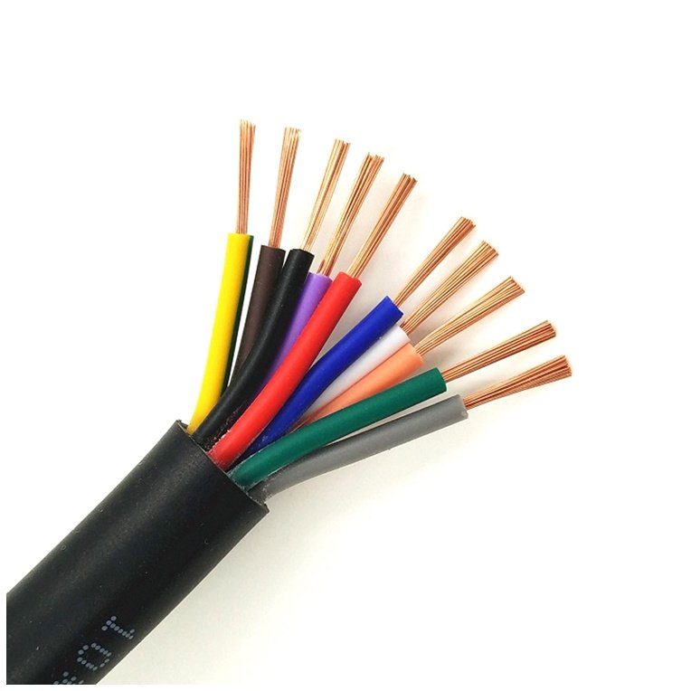
Plug the wrong cable into the wrong application and the consequences range from annoying to genuinely dangerous. A warehouse supervisor who grabs a standard flexible power cable to jury-rig a device charging station, or a procurement manager who specifies a USB charging cable where a proper IEC 60227-rated flexible cord belongs, is inviting either a fire risk or a bricked device — sometimes both. The distinction matters operationally, and it has real cost implications when you’re sourcing at volume or designing a system from scratch.
A power cable and a charger cable are not the same thing. A power cable is a passive conductor that delivers raw AC or DC electrical energy from one point to another, with no voltage conversion or regulation. A charger — whether a wall adapter or a USB-C Power Delivery cable with an embedded chip — actively conditions that energy to suit a specific device. The cable itself does not charge; the charging system does.
What makes this genuinely interesting is where the line blurs. Modern USB-C cables rated for 240 W under USB PD 3.1 carry conductors large enough that, on paper, they begin to resemble the lower end of the IEC flexible power cable range — and yet the two are built to entirely different standards, tested against different failure modes, and designed for different circuit environments. Understanding exactly why they diverge tells you something useful about cable engineering that most spec sheets never bother to explain.
Defining a Power Cable: Construction, Function, and Industrial Role
A power cable is, at its core, a passive electrical conductor assembly. It moves energy from one point to another — full stop. It does not transform voltage, does not rectify AC to DC, does not regulate current, and contains no active electronic component of any kind. That passivity is not a limitation; it is the entire engineering point. The cable’s job is to be an efficient, reliable, thermally stable conductor of electrical energy, and every design decision in its construction serves that narrow purpose.
How a Power Cable Is Actually Built
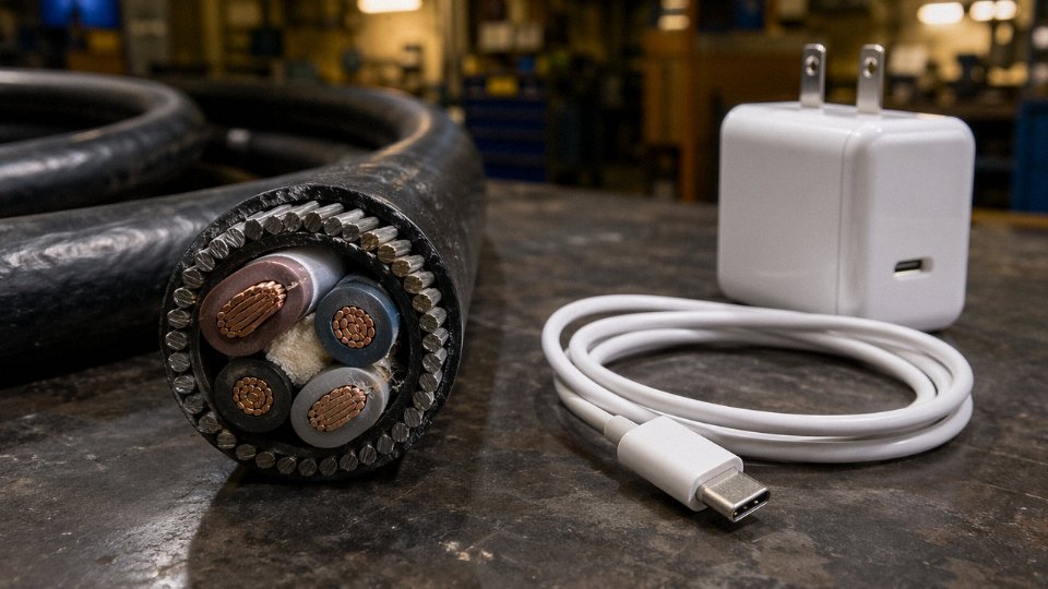
Walk any production floor where medium- or high-voltage cables are made, and you will see the same layered logic repeated regardless of the final voltage rating. The innermost element is the conductor — stranded or solid copper, or increasingly aluminium for larger cross-sections where weight and cost matter more than conductivity. Conductor sizes in industrial power cables run from roughly 0.5 mm² for light-duty flexible wiring up to 630 mm² for heavy feeder and substation work, and the choice of copper versus aluminium shifts the whole downstream calculation: aluminium needs a larger cross-section to carry equivalent current, but on a per-kilometre basis for transmission runs above, say, 95 mm², it is often the more economical option.
Around the conductor sits the insulation, and this is where the voltage rating starts to define the design. PVC insulation (covered under IEC 60227 for cables rated up to 450/750 V) is workable, cheap, and widely understood by electricians everywhere, but it softens at elevated temperatures and carries flame-propagation risks in enclosed spaces. XLPE — cross-linked polyethylene — handles higher continuous operating temperatures, typically up to 90°C compared to 70°C for standard PVC, which matters enormously in tightly routed industrial trays. EPR (ethylene propylene rubber) appears in flexible applications and in cables expected to flex repeatedly without cracking in cold environments; you see it on offshore platforms and mining equipment. Above the insulation, depending on the cable construction, come filler, bedding, armour (steel wire armour for direct burial or mechanical protection, aluminium wire armour where weight or corrosion is a concern, or steel tape armour for lighter mechanical protection), and an outer sheath — usually PVC or polyethylene.
Voltage Classes and Why They Matter to Buyers
Low-voltage cables — up to 1 kV — cover the vast majority of commercial building wiring, panel feeds, motor circuits, and light industrial distribution. IEC 60502-1 governs extruded solid dielectric insulated cables in this range, and its counterpart GB/T 12706 is the Chinese national standard that manufacturing facilities in Shandong, Jiangsu, and elsewhere build to when supplying export markets. Medium-voltage cables (roughly 1 kV to 35 kV) serve industrial substations, wind farm collection networks, and underground urban distribution; IEC 60502-2 applies here. High-voltage cables above 35 kV are a different engineering discipline entirely — jointing alone requires specialist training, and procurement lead times can stretch to months.
IEC 60502 defines the construction and testing requirements for power cables, not for charging devices or consumer electronics cables.True
IEC 60502 specifically covers extruded solid dielectric insulated power cables for rated voltages from 1 kV up to 30 kV. USB charging cables fall under entirely separate specifications including USB-IF standards and IEC 62680, with no overlap in scope.
No Electronics. Ever.
This point cannot be stated plainly enough for anyone comparing power cables to chargers: a power cable contains no rectifier, no transformer winding, no charge-management IC, no voltage regulator, and no communication circuitry. None. The energy that enters one end leaves the other end at the same voltage, the same frequency, and — minus resistive losses — the same waveform. That is not a simplification; it is the regulatory and physical definition of what separates a passive cable from an active power conversion device.
Jinda’s manufacturing scope — five production bases across China, 470,000 m² of floor space, production lines ranging from low-voltage flexible cables through high-voltage extruded cables, supplying customers in more than 50 countries — reflects what industrial-scale passive cable manufacturing actually looks like. The sheer volume and range of product only makes sense for a passive commodity: copper rod in, insulated and armoured cable out, tested to IEC and GB/T standards, shipped to a grid project or factory somewhere that needs reliable energy transport and nothing more exotic than that.
Defining a Charger: Active Electronics, Energy Conversion, and Battery Management
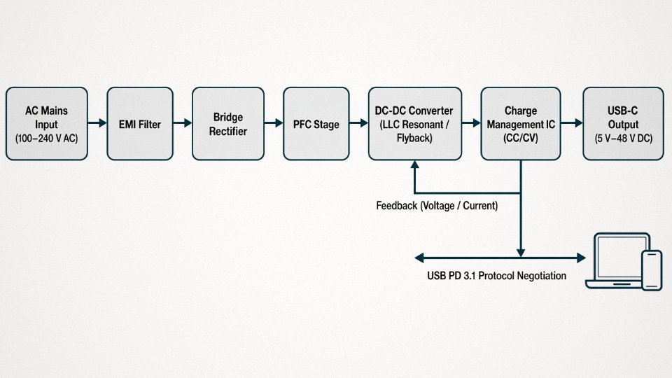
A charger is not a cable. It is not a passive conductor. Strip away the housing and what you find is a layered stack of active electronic circuitry whose entire job is to accept whatever electrical supply is available — typically 100–240 V AC from a wall socket, or sometimes a 12–48 V DC bus in a vehicle or industrial setting — and transform it into a tightly regulated DC output that matches what a specific battery or device actually needs at that precise moment in its charge cycle. That transformation requires semiconductors, control logic, feedback loops, and thermal protection. A copper conductor does none of those things.
What Is Actually Inside a Charger
Walk through the functional blocks and the engineering complexity becomes obvious fast.
The AC-DC rectification stage converts the incoming mains sine wave to raw DC — usually an unregulated, lumpy rail that would destroy a lithium cell if applied directly. Ahead of or integrated with this is a power factor correction (PFC) circuit, which in any charger above roughly 75 W is mandatory under IEC 61000-3-2 to keep the current draw from looking like a distorted spike to the grid. Cheap chargers omit proper PFC; that is one of the first things worth checking in a procurement spec.
The DC-DC conversion stage — typically a flyback or LLC resonant converter in the 5–65 W range, moving to phase-shifted full-bridge topology for EV and industrial chargers above a few kilowatts — steps the rectified rail down to the output voltage the device expects, anywhere from 5 V for a phone to 400–800 V for an EV battery pack.
Then comes the part that actually does battery management: the charge management IC, running a constant-current / constant-voltage (CC/CV) algorithm at minimum, and in more sophisticated designs a multi-stage profile that monitors cell temperature, state of charge, and impedance. Texas Instruments, NXP, and a handful of other suppliers dominate this segment. The IC decides when to taper current, when to stop, and — critically — when something is wrong enough to shut the whole thing down.
Thermal management is not optional. A charger dissipating even 5–8 W internally in a pocket-sized enclosure will throttle output or fail prematurely without adequate heatsinking or airflow design. Industrial and EV chargers use forced-air or liquid cooling; consumer bricks rely on the thermal mass of the enclosure and derating curves baked into the firmware.
Finally, modern chargers carry communication protocols — USB Power Delivery (USB PD), Qualcomm Quick Charge, or proprietary variants — that let the charger and device negotiate voltage and current in real time. A USB-C PD 3.1 charger can supply anywhere from 5 V up to 48 V at up to 5 A, but only because both ends agreed to those parameters over a data channel. The cable between them is passive; the negotiation happens in the silicon at each end.
Three Terms Consumers Conflate
This is where most of the practical confusion lives.
The charger unit (the “brick” or “adapter”) is the active electronic device described above. The charging cable — a USB-C, Lightning, or proprietary lead — is still fundamentally a passive cable: conductors, insulation, connectors, and in USB-C’s case a small E-Marker chip that identifies cable capabilities to the PD controller. It carries low-voltage DC and data signals. It is engineered to tight tolerances for that specific application, but it does not convert or regulate anything. The power supply cable is the mains cord that feeds the charger unit from the wall socket — an IEC 60320 C7 or C13 lead, for instance, governed by IEC 60227 like any other flexible power cable.
A USB-C charging cable contains active charging circuitry that converts voltage for the connected device.False
A USB-C cable is a passive conductor with data lines. The E-Marker chip in some cables only identifies the cable's current and voltage ratings to the charger and device controllers — it does not perform any power conversion. All active regulation happens inside the charger unit and the device's charge management IC.
The regulatory boundary reflects exactly this distinction. Charger units and charging cables fall under consumer electronics safety standards — IEC 62368-1 for audio/video and IT equipment, USB-IF specifications, and in the EU the Common Charger Directive (2022/2380) — none of which apply to industrial power cables. Power cables are certified under IEC 60502, IEC 60227, IEC 60245, and their regional equivalents. Submitting a charging cable for IEC 60502 type testing, or specifying a power cable to IEC 62368-1, would be the wrong standard for the wrong product. In a real procurement audit, that mismatch is a red flag.
Side-by-Side Technical Comparison: Voltage, Current, Frequency, and Signal Handling
The gap between a power cable and a charging cable is not subtle once you look at the actual specifications. Put them in a table and the difference is almost uncomfortable — they barely share a product category in any meaningful engineering sense.
| Parameter | Industrial / Building Power Cable | USB Charging Cable |
|---|---|---|
| Rated voltage | 300/500 V (flexible) up to 500 kV (HV transmission) | 5 V – 48 V DC (signal-side); no AC rating |
| Current capacity | ~1 A (0.5 mm²) to several thousand amps (630 mm², bundled) | 0.5 A – 5 A depending on USB spec and conductor gauge |
| Conductor cross-section | 0.5 mm² – 630 mm² | 0.08 mm² (28 AWG) – 0.52 mm² (20 AWG) |
| AC / DC operation | Both; most distribution cables rated for 50 Hz or 60 Hz AC | DC only on power conductors; high-frequency data signals on comms conductors |
| Active components | None — purely passive | None in the cable itself; active e-marker IC in USB-C cables above 60 W |
| Insulation system | PVC, XLPE, EPR, LSZH — rated to voltage class | Thin PVC or TPE jacket; no voltage-class rating required |
| Governing standards | IEC 60227, IEC 60245, IEC 60502, IEC 60840 and above | USB-IF specifications; IEC 62680; EU Common Charger Directive 2022/2380 |
| Mechanical design brief | Fixed installation or controlled flexing; conduit, tray, buried trench, harsh industrial | Consumer repeated flex, compact molded connectors, light weight |
| End-use role | Transmit bulk electrical energy, passive throughout | Carry DC output from charger to device; carry communication data |
Voltage and Current: Orders of Magnitude Apart
A standard flexible power cable to IEC 60227 is rated at 300/500 V at the low end — and that’s the entry level. Medium-voltage XLPE cables run 6 kV to 35 kV; high-voltage transmission cables push past 220 kV and in some grid applications reach 500 kV. Current-carrying capacity scales with conductor cross-section and installation method, ranging from a handful of amperes in a 0.5 mm² control cable up to several thousand amperes in large 630 mm² conductors or parallel-run busbar systems. The exact figure depends on ambient temperature, grouping, soil thermal resistivity if buried, and installation depth — no honest engineer quotes a single number without those conditions attached.
USB charging cables exist in a different universe. Under USB PD 3.0, the ceiling is 5 A at 20 V — 100 W. USB PD 3.1 pushed the voltage to 48 V, giving 240 W, which sounds impressive until you remember that a household extension cord rated at 10 A / 250 V is already handling 2,500 W without any sophisticated electronics involved. The charging cable’s conductors — typically 20 AWG to 28 AWG — physically cannot carry industrial current. Connecting a high-current load to a USB cable would melt the insulation well before tripping any protection device.
USB-C cables rated above 60 W are required to contain an e-marker chip that communicates cable capability to the charger and device.True
The USB Power Delivery specification mandates an electronically marked (e-marker) IC in full-featured USB-C cables rated for over 60 W or 3 A, allowing the charger to verify cable rating before sourcing higher current. Without this chip, the system defaults to the lower current limit.
Frequency Handling and Skin Effect
Industrial power cables carrying 50 Hz or 60 Hz AC face real dielectric loss and, at higher voltage classes, skin-effect losses that influence conductor design. Above roughly 1 kV, cable designers start caring about the conductor’s AC resistance versus DC resistance ratio. At medium and high voltage, XLPE insulation is specified partly because its dielectric loss tangent is far lower than standard PVC — that matters at sustained high voltage even at power-frequency. None of this applies to a charging cable, which carries DC on its power conductors. What the charging cable does carry alongside that DC is high-frequency communication data — USB 2.0, USB 3.x, or Thunderbolt signaling — which demands controlled differential-pair impedance and careful shielding. That is a completely different engineering problem from managing 50 Hz dielectric loss, and it’s why the two cable types are designed, tested, and certified under entirely separate frameworks.
Mechanical and Environmental Reality
Power cables going into a conduit or buried trench are designed to stay there. Armoring, moisture-blocking compounds, UV-stabilized outer sheaths, and crush-resistance ratings all reflect an installation environment that is largely static once the cable is pulled. Even “flexible” power cables — the kind on portable tools or festoon systems — are engineered for controlled, repetitive bending at defined minimum bend radii, usually specified in multiples of the cable’s overall diameter.
Charging cables are designed to be abused by consumers who coil them tightly, stuff them in bags, and yank them by the connector. The mechanical design brief centers on flex endurance at the connector entry point, compact overmolded strain relief, and low weight. Some premium cables add aramid fiber reinforcement inside the jacket specifically to survive that kind of handling — but their conductor cross-section and voltage rating remain firmly in the consumer-electronics tier. Rugged and thin are not the same as industrial-grade.
The practical upshot for procurement: specifying a cable means specifying the right engineering category from the start. Conflating the two not only risks a non-compliant installation — it usually means either gross over-engineering or a genuine safety failure, depending on which direction the mistake goes.
Where the Language Gets Confusing: EV Charging Cables, Industrial Chargers, and Hybrid Assemblies
The straightforward cable-versus-charger distinction holds up well in most contexts. Then you walk onto an EV charging site or into a forklift battery room, and suddenly the vocabulary starts to buckle. These are the genuine grey zones — assemblies that look like cables, are sold and specified like cables, but carry names and functions that blur the boundary.
EV Charging Cables: Power Assembly, Not a Charger
The cable assembly hanging from a wall-mounted EVSE or a DC fast-charger post is commercially the most important example of this confusion. It contains everything you’d expect from a serious power cable — copper conductors sized anywhere from roughly 6 mm² at 32 A (typical AC Level 2) up to 95 mm² or larger for DC fast-charging stations pushing 350–500 A — plus something a standard power cable never carries: pilot signal conductors.
Per IEC 61851-1, that assembly includes a Control Pilot (CP) conductor and a Proximity Pilot (PP) conductor. The CP line carries a 1 kHz PWM signal that negotiates charging current limits between the vehicle and the EVSE. The PP line detects whether the connector is physically seated. Some DC charging cables also carry low-voltage communication lines for CAN bus or PLC-based protocols. So the finished assembly is a multi-function cable — power conductors, signal conductors, sometimes a dedicated PE conductor sized independently — but it is still a passive assembly. It moves electrons and signals. It converts nothing.
Where does the active intelligence live? For AC Level 2 charging, the EVSE box on the wall handles metering and safety switching, but the actual AC-to-DC conversion happens inside the vehicle in the on-board charger module. The cable is just the conduit. For DC fast charging, the rectification and output regulation happen inside the charger cabinet — often a substantial piece of power electronics — before any current enters the cable. By the time electrons reach that tethered cable, they are already conditioned DC at the target voltage. The cable remains passive regardless of how much computing happened upstream.
An EV charging cable assembly is classified as a charger under IEC 61851-1.False
IEC 61851-1 governs the EV conductive charging system as a whole, including the EVSE and the vehicle interface. The cable assembly itself is a specialised power cable assembly; the active charging electronics reside in the EVSE or the DC charger unit, not in the cable.
Industrial Battery Charger Interconnects
Forklift battery rooms are worth a look here. A 48 V lead-acid or lithium traction battery connects to its charger via a heavy DC cable — typically 35 mm² to 95 mm², depending on the charge current and run length — with a colour-coded connector rated for frequent mate-unmate cycles. UPS systems and stationary energy storage racks use similar arrangements. These cables run at DC bus voltages of 24 V, 48 V, 110 V, or 400 V depending on the system, and they can carry charge currents in the hundreds of amperes during bulk charge phases. High current, DC, temperature-rated insulation — they are power cables, specified and sourced as power cables, from cable manufacturers. The charger unit with its transformer, rectifier bridge, and BMS communication sits separately in the cabinet.
Solar PV DC Cables
Informally, you will hear these called “solar charger cables.” The proper classification — IEC 62930, or the widely used PV1-F designation — puts them firmly in the power cable category. They carry DC output from panels to string inverters or combiner boxes, rated for outdoor UV exposure, often 1,000 V DC or 1,500 V DC system voltage. The inverter is the active device; the cable is not.
Why Getting the Category Wrong Costs Real Money
Customs classification is where this confusion bites hardest in procurement. Power cables generally fall under HS code 8544 (insulated wire, cable, and other insulated electric conductors). Chargers and power converters sit under 8504. Misclassifying a DC fast-charger unit as a cable — or vice versa — triggers reclassification by customs, potential back-duties, and shipment holds that can run weeks on a time-sensitive project. Warranty disputes follow the same fault line: a cable manufacturer’s warranty covers the passive assembly; if an electronics fault in the EVSE causes cable overheating, each party points at the other’s product category. Specifying clearly from the start — cable assembly from a cable supplier, charging electronics from a power electronics supplier — keeps those boundaries clean and the liability unambiguous.
Safety, Standards, and Certification Requirements That Separate the Two Products
The regulatory frameworks for power cables and chargers don’t just differ in detail — they occupy entirely separate branches of the standards tree. Getting this wrong at the procurement stage isn’t a paperwork problem; it’s a liability problem.
Power Cable Standards: A Layered System Built Around Voltage Class and Installation Context
IEC 60227 and IEC 60245 cover the flexible, lower-voltage end — PVC-insulated and rubber-insulated cables up to 450/750 V respectively. These are your H05VV-F extension cords, your machine-tool trailing cables, your general-purpose flexible wiring. Step up to medium-voltage distribution and you’re in IEC 60502 territory (1 kV to 30 kV, extruded solid dielectric insulation), with IEC 60840 and IEC 62067 governing high-voltage cables above 30 kV where dielectric design and partial discharge testing dominate the qualification process. None of these standards have anything to say about battery chemistry, charge termination logic, or USB connector pin assignments. They are purely about safe energy transmission through an insulated conductor.
In Europe, EN 50575 adds a layer that most procurement managers outside the construction sector don’t think about until it bites them: reaction-to-fire classification under the Construction Products Regulation (CPR). Cables installed inside buildings must carry a CPR fire class — Aca down through Fca — declared by the manufacturer and backed by a Declaration of Performance. A cable without a valid DoP cannot legally be installed in a European building. China’s GB/T 12706 is broadly harmonised with IEC 60502 for medium-voltage cables, which simplifies cross-border specification work, though test lab recognition and documentation requirements still differ enough to cause delays if you assume they’re interchangeable.
LSZH (low-smoke zero-halogen) requirements per IEC 60332 apply to cables routed through confined spaces — tunnels, ships, rail rolling stock — where halogen combustion gases kill people before the fire does. A USB charging cable on an office desk is never subject to this. That distinction matters when a fire marshal or building inspector starts asking questions.
Charger and Charging Cable Standards: Electronics Safety Meets Interface Specification
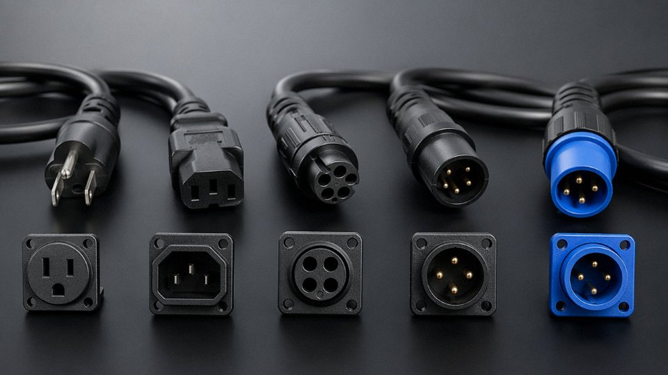
IEC 62368-1 is the current governing safety standard for chargers, adapters, and power supplies — it replaced both IEC 60950-1 (IT equipment) and IEC 60065 (audio/video) and takes a hazard-based approach rather than a prescriptive circuit-by-circuit one. A USB-C charger submitted for UL listing or CE marking goes through IEC 62368-1 testing at the assembly level, including the cable and connector. The cable alone, in this context, is not independently certified — it’s evaluated as part of the system.
USB-IF’s Power Delivery specification and IEC 62680 govern the electrical and communications interface: voltage negotiation, current limits, cable identification via the e-marker IC in USB-C cables rated above 60 W. If a cable claims PD 3.1 compliance (up to 240 W, 48 V) and doesn’t carry a properly programmed e-marker, the charger’s controller will cap the session at 60 W at best, or refuse to negotiate at all. That’s a warranty return waiting to happen.
The EU Common Charger Directive (Delegated Regulation 2022/2380) mandates USB-C on consumer devices phased in from 2024 through 2026 depending on device category. From a procurement standpoint, this means legacy proprietary charging cables are being designed out of new consumer product lines across the EU market — a supply chain shift that’s already visible in RFQ volumes.
CE marking on a power cable and CE marking on a USB charger indicate compliance with completely different EU directives.True
CE on a power cable primarily confirms compliance with the Low Voltage Directive (LVD 2014/35/EU) and, for fixed installation cables in buildings, the Construction Products Regulation (CPR). CE on a charger covers LVD plus the Radio Equipment Directive (RED) if any wireless charging function is present — a fundamentally different conformity assessment path.
Customs Classification: Where the Regulatory Split Has Real Financial Consequences
Power cables — insulated conductors without connectors or active electronics — are classified under HS code 8544.49. Battery chargers and AC adapters fall under 8504.40. The duty rates differ by jurisdiction, sometimes significantly, and the documentation required at customs differs too.
Misclassifying a charger assembly as a cable to take advantage of a lower tariff is the kind of shortcut that triggers an audit. In practice, a shipment of USB-C charging cables with e-marker ICs will draw scrutiny if declared under 8544 — the active component disqualifies it. Getting the HS code right from the start, with a clear bill of materials that distinguishes passive conductor assemblies from active device assemblies, is cleaner and cheaper than fighting a reclassification after the fact.
Practical Selection Guide: Choosing the Right Power Cable for Your Application
Getting the conceptual distinction straight is one thing. Actually specifying the right cable for a real job is where engineers earn their keep — and where mistakes cost real money.
Start With Voltage Class — Everything Else Follows From It
System voltage drives almost every downstream decision: insulation wall thickness, the relevant standard family, permissible installation methods, and how much of your supply chain gets complicated.
Low-voltage systems (up to 1 kV AC, per IEC 60038) cover the vast majority of industrial plant wiring, commercial buildings, and appliance connections. Medium-voltage cables — typically 3.6/6 kV up to 36 kV — appear in utility distribution feeders, large industrial substations, and wind farm collector circuits. High-voltage cables above 36 kV are a specialist category with their own jointing and testing requirements that most plant engineers never touch directly, but procurement teams on infrastructure projects absolutely need to identify correctly early. Mixing these up at the specification stage is not just a technical error; it can delay a project by weeks when the wrong cable arrives on site and needs to be returned.
Installation Environment Is Not a Secondary Consideration
Where the cable lives determines more about its construction than almost any other factor. Direct burial requires mechanical protection and moisture resistance — typically XLPE-insulated SWA (steel wire armour) for LV or IEC 60502-2 XLPE MV cables with appropriate bedding and oversheath. Cable tray in a dry industrial plant can use unarmoured or steel tape armoured construction. Conduit runs allow lighter constructions since the conduit itself provides mechanical protection. Hazardous areas (Zone 1 or 2 per IEC 60079) mandate flame-retardant, often LSZH oversheaths, and in some classifications the cable must carry Ex certification itself.
Offshore and marine environments are genuinely punishing — mud, oil, salt spray, mechanical shock from vessel movement. IEC 60092 compliance is the baseline, and buyers should verify the oversheath compound, not just the certificate number.
Conductor Sizing: Where the Tables Meet the Real World
IEC 60364-5-52 and NEC 310 both provide current-carrying capacity tables, but published values assume specific baseline conditions — usually a single circuit, 30 °C ambient, a particular installation method. Real installations rarely match those baselines. Correction factors for grouping (multiple cables in a tray reduce heat dissipation), elevated ambient temperature in a machine room or desert installation, and installation method can collectively derate a cable’s capacity by 40–60% from the tabulated value. Undersizing conductors here is one of the more common mistakes on fast-moving projects.
Voltage drop matters too, especially on long runs. Most industrial codes permit a maximum 3–5% voltage drop under full load; a 500 m feeder to a remote pump station may require stepping up conductor cross-section well beyond what the thermal limit alone would dictate — sometimes by two or three sizes.
Short-circuit withstand rating is the third leg of sizing that gets skipped when schedules are tight. The conductor must survive the fault current for the duration it takes the upstream protection to clear. Undersized conductors can be damaged or destroyed before the breaker trips.
Armour Selection in Practice
The armour type is not interchangeable, and this trips up procurement teams who treat it as a cosmetic spec.
| Armour Type | Typical Use Case | Key Reason |
|---|---|---|
| Steel Wire Armour (SWA) | Direct burial, multi-core LV/MV cables | High tensile and crush resistance |
| Aluminium Wire Armour (AWA) | Single-core AC cables | Avoids eddy-current heating in steel; lighter |
| Steel Tape Armour | Indoor trays, limited mechanical risk | Adequate protection, more flexible than SWA |
| None (flexible cord) | Portable equipment, appliance connections | Requires frequent flexing; armour would crack |
Using SWA on a single-core AC cable is a real mistake made in the field — the steel forms a shorted magnetic loop around a single current-carrying conductor, generating circulating currents and heat that will shorten cable life noticeably and increase losses.
Application-to-Cable-Type Reference
| Application | Cable Type | Governing Standard |
|---|---|---|
| Utility power distribution | XLPE MV, Cu or Al conductor | IEC 60502-2 |
| Industrial plant wiring | Armoured LV, SWA/AWA, PVC or XLPE | IEC 60502-1 |
| Marine and offshore | Mud/oil-resistant, tinned Cu | IEC 60092 |
| Solar PV DC systems | Single-core PV cable, cross-linked insulation | IEC 62930 |
| Wind turbine interconnects | Flexible torsion-rated, MV or LV | IEC 61892 / project spec |
| EV charging infrastructure | Flexible EV cable, LSZH sheath | IEC 62893 |
| Mining, hazardous areas | Flame-retardant trailing cable | IEC 60079, IEC 60245-4 |
Fire Performance and Environmental Resistance
LSZH (Low Smoke Zero Halogen) compound is now specified by default on most transport, tunnel, and public building projects — it reduces toxic gas emission during fire, which matters enormously in confined spaces. Oil-resistant oversheaths (typically PCP or special PVC compounds) are non-negotiable in hydraulic press areas or marine engine rooms. UV stabilisation is required for any cable running outdoors without conduit — standard black PVC will chalk and crack within a few seasons of direct sunlight in high-UV climates.
LSZH cables produce significantly lower toxic gas emissions than standard PVC cables when exposed to fireTrue
LSZH compounds are formulated to minimise halogen acid gas and smoke density during combustion, a requirement verified under IEC 60754 and IEC 61034 test standards — this is not marketing language, it is a measurable, testable property.
Reducing Supply Chain Complexity on Multi-Country Projects
One practical reality on large infrastructure or multi-site industrial projects: managing five or six cable suppliers across LV feeders, MV distribution, EV charging infrastructure, and special industrial cables creates coordination overhead that quietly eats engineering hours and procurement budget. A supplier with genuine breadth across LV, MV, and HV power cables, LSZH variants, EV charging cables, and special-duty industrial cables — with R&D, production, testing, and after-sales under one roof — reduces that overhead substantially. Jinda’s integrated manufacturing base, covering that full range, means a procurement team can consolidate technical queries, documentation packages, and delivery scheduling through a single point of contact rather than chasing multiple vendors for a single project’s cable schedule. For international projects spanning different national codes, that kind of integrated technical support is worth evaluating early rather than discovering the gap during factory acceptance testing.
Common Mistakes in Industrial and Commercial Cable Procurement That Cost Time and Money
Procurement errors in this space rarely come from ignorance of electricity. They come from vocabulary drift — engineers and buyers using “cable” as a catch-all, then discovering mid-project that the product delivered doesn’t meet the installation code, the machine standard, or the customs declaration. Each mistake below has a real cost attached: re-work labour, held shipments, failed inspections, or scrapped wiring harnesses.
Ordering a Flexible Appliance Cord for a Fixed Panel Installation
This one shows up more than it should. A project manager needs cable for an industrial control panel, sees H05VV-F or H07RN-F in stock, and orders it because the voltage and current ratings look fine on paper. They’re not wrong about the electrical ratings — they’re wrong about the application class.
Flexible cords are designed for repeated movement and temporary connection. Most electrical installation codes, including IEC 60364 and national derivatives, explicitly prohibit flexible cords in permanent fixed-wiring applications inside panels or conduit. Inspectors know what the insulation markings mean. A failed inspection at commissioning typically costs somewhere between two and six weeks of re-work depending on panel complexity, plus the cost of pulling and replacing cable that was already terminated. Insurance underwriters have voided coverage on industrial fires where non-compliant wiring was found — that’s not a theoretical risk.
The correct choice is a fixed-wiring cable to IEC 60228 Class 1 or Class 2 conductor construction, with insulation and sheath compounds rated for the installation environment.
Using a USB Charging Cable in a Low-Voltage DC Control Circuit
It happens, usually on small machines built by mechanical engineers who are less familiar with IEC 60204-1 machine wiring rules. A USB cable is physically convenient, it carries 5 V or 12 V DC just fine in a bench test, and it’s cheap. The problems emerge later: USB cables carry no temperature rating suited to enclosures that regularly reach 70–85 °C, the shielding (if present at all) isn’t matched to the machine’s EMC requirements, and the cable has no installation markings whatsoever. Maintenance technicians can’t trace it, can’t verify its rating, and can’t replace it with a compliant equivalent without documentation.
USB charging cables comply with IEC 60204-1 machine wiring requirementsFalse
IEC 60204-1 requires conductors to be identified, rated for the thermal environment, mechanically protected for the installation method, and sourced to traceable specifications. Consumer USB cables meet none of these criteria and are not listed in the standard's acceptable wiring materials.
Substituting a Standard Armoured Power Cable for an EV Charging Cable
An EV charging cable is a specialised assembly, not a power cable with a bigger plug on the end. IEC 62196 Type 2 AC charging and CCS Combo 2 DC fast-charging assemblies require pilot and proximity conductors that carry low-level signalling between the vehicle, the EVSE, and the grid interface. Without those conductors functioning correctly, the charging session simply won’t initiate — the handshake protocol fails. Beyond that, EV cables flex hundreds or thousands of times across their service life, outdoors, in sub-zero temperatures and UV exposure. Standard PVC-jacketed SWA cable cracks. The jacket compound needs to be TPU or a suitable rubber compound rated for that duty.
Customs Misclassification Between HS 8544 and HS 8504
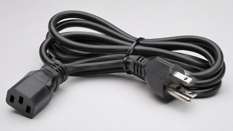
Cables fall under HS 8544; chargers and power conversion equipment fall under HS 8504. When a procurement team bundles a shipment containing both power cables and charger adapters under a single HS code — usually 8544 because “it’s all cables” — customs authorities at the destination port flag the mismatch during inspection. The result is a hold, re-classification, possible penalty duties, and delays that in my experience run anywhere from five days to three weeks depending on the port and the volume of documentation required to correct the declaration. For cross-border procurement from Chinese manufacturers, where mixed shipments are common and commercial invoices don’t always itemise by HS code, this is a routine enough problem that it’s worth building a line-item HS verification step into your purchase order process.
Ignoring Fire Performance Class Under the EU Construction Products Regulation
Post-CPR enforcement is uneven across EU member states, but it’s tightening. Cables installed in EU buildings are required to carry a valid Declaration of Performance and a fire class marking — Eca at minimum for most general wiring, Dca or better for escape routes and public buildings. Catalogue pages from manufacturers who don’t explicitly show CPR status are a warning sign; it usually means the product hasn’t been tested and classified under EN 13501-6. Installing non-compliant cable isn’t just a code violation — it can invalidate building insurance and, in the event of a fire investigation, expose the installing contractor to significant liability. Check the DoP before the order goes in, not after the cable arrives on site.
Frequently Asked Questions
Is a power cable the same as a charger?
No — and the difference is not just semantic. A power cable is a passive conductor: copper or aluminium conductors wrapped in insulation and jacket, transmitting electrical energy from point A to point B without altering it in any way. A charger is an active electronic device containing a transformer, rectifier, switching circuitry, and battery-management logic. It converts mains AC to regulated DC at whatever voltage and current profile a specific battery chemistry demands. The cable that runs between a charger brick and your phone is a charging cable — still a passive conductor, just rated for low-voltage DC service. Three distinct objects; one badly overloaded word.
Can I use a regular power cable to charge a device?
Not directly, and attempting it would be destructive. A standard mains power cable carries 120 V or 230 V AC — roughly 170 to 325 V peak — directly to whatever you connect to its terminals. Consumer device batteries typically charge at 3.7 V to 12 V DC. Connecting mains voltage to a device’s charging port would flash-over the battery management IC, likely start a fire, and void any warranty faster than you can blink. The cable cannot regulate, convert, or step down voltage. That is the charger’s job entirely.
A standard power cable can be used to charge a smartphone if the voltage is low enoughFalse
A power cable is a passive conductor with no voltage regulation or conversion capability. It delivers whatever voltage is present at the source. Only a charger — an active electronic device — can convert and regulate mains power to the low-voltage DC required by a device battery.
What is the difference between a power cord and a charging cable?
A power cord — think IEC C13 kettle lead, or a heavy-duty H07RN-F flexible cable on industrial equipment — is designed to carry mains AC power. Conductor cross-sections range from around 0.75 mm² for light loads up to several hundred mm² for high-current industrial runs, and the insulation is rated for 300/500 V or 450/750 V depending on type. A USB-C charging cable, by contrast, carries 5 V to 48 V DC, uses conductors in the 0.08 mm² to 0.52 mm² range, and is engineered to pass USB-IF compliance testing for signal integrity and connector retention force. The connectors, standards, voltage classes, and regulatory bodies are completely different. You would not spec one in place of the other, ever.
Is an EV charging cable a power cable or a charger?
Technically a specialised power cable — and this trips up a lot of people including some procurement folks who should know better. The cable assembly carries high-current AC (typically 32 A to 63 A at 400 V on three-phase European installations) or DC (up to 500 A on CCS fast chargers) plus pilot signal conductors for communication, but it contains no active electronics. The rectification, power factor correction, and charge management happen inside the EVSE wallbox or the DC fast-charger cabinet. IEC 62893 covers the cable itself; IEC 62196 covers the connectors. When someone calls the whole station a “charging cable,” they’re collapsing the assembly into one label — understandable in casual conversation, genuinely problematic when writing a procurement specification.
What standards govern power cables versus charging cables?
Power cables fall under IEC 60502 (medium voltage), IEC 60227 and IEC 60245 (flexible and fixed wiring cables for general use), plus national derivatives. Consumer charging cables are governed by IEC 62368-1 for safety, USB-IF specifications for performance, and — inside the EU — the Common Charger Directive 2022/2380 which now mandates USB-C on most portable devices. EV charging cables specifically follow IEC 62893. These are separate standards committees, separate test labs, and in many countries separate import certification regimes, so conflating the product categories in a BOM creates compliance headaches that can delay a product launch by weeks.
How do I know which cable I need for an industrial installation?
Start with five parameters: system voltage, continuous current load, installation environment (buried, tray, conduit, free-hanging, exposed to oil or UV), required mechanical duty (flexible reeling, fixed, drag-chain), and fire performance class. From those five you can narrow to an IEC cable type reasonably quickly. Voltage and environment usually eliminate the most options. Fire performance — whether you need IEC 60332-3 flame retardance, IEC 60754 low halogen, or IEC 61034 smoke density compliance — depends on the building type and local code. For projects where the spec involves multiple cable types across high-voltage feeders, instrumentation runs, and control cables, working with a manufacturer that carries full technical support alongside production capacity — Jinda’s team handles exactly this kind of multi-type project coordination — tends to catch errors before they become change orders.
Are solar PV cables considered power cables or charger cables?
Power cables, unambiguously. A PV1-F type solar DC cable (classified under IEC 62930) is a passive conductor moving DC power from the panel array to the inverter or charge controller. It uses tinned copper conductors, cross-linked polyethylene insulation, and UV-resistant outer sheathing to handle outdoor DC service — typically up to 1,500 V DC on modern utility-scale strings — but it performs no energy conversion whatsoever. The “charging” of the battery bank or the grid feed-in process is handled by the charge controller or inverter downstream. The cable is just the conductor. Calling it a charger cable because it sits inside a solar charging system is like calling a garden hose a water treatment plant.
Why Sourcing Power Cables from a Vertically Integrated Manufacturer Reduces Project Risk
Every large cable procurement project carries a risk model that most buyers underestimate until something goes wrong. The supply chain for a finished power cable runs through at least six or seven distinct process stages — copper rod sourcing, wire drawing, stranding, insulation extrusion, armour application, outer sheathing, and final electrical and mechanical testing. When each of those stages happens at a different facility, potentially under different ownership, quality control becomes a game of telephone. A conductor drawn to slightly loose tolerances at stage two may still pass incoming inspection at stage three, only to cause elevated resistance or premature insulation stress a year into service. By then, the project is commissioned, the warranty period is running, and tracing the root cause back through a multi-tier chain is an exercise in frustration.
Vertical integration collapses that chain. When one manufacturer controls raw material processing through finished-cable dispatch under a single QA system, there is one throat to grab if something is wrong — and more importantly, far fewer opportunities for a defect to originate or hide in the first place.
What Vertical Integration Actually Looks Like in Practice
At Jinda, the operation spans five production bases across China totalling roughly 470,000 m² of manufacturing space. That is not just floor space for assembly; it covers the upstream processing that most cable “manufacturers” quietly outsource. In-house R&D handles product development and keeps the portfolio current with evolving standards — IEC, CE, UL, CCC — rather than waiting for a supplier to inform them of a compliance gap. Dedicated export and logistics teams manage certification documentation, HS code accuracy, and certificate of origin preparation, which matters enormously when a container of MV cable arrives at a port and customs want to see paperwork that matches the product exactly.

Project Types Where This Distinction Earns Its Value
Utility infrastructure projects are the clearest case. A type-tested medium- or high-voltage cable installation requires factory acceptance test (FAT) documentation that traces back to actual production records — drum numbers, batch dates, test results. A trading company assembling product from multiple sources cannot produce that traceability coherently. It is also worth noting that long-run consistency matters differently for different project types. A renewable energy installation — say, a solar farm requiring several kilometres of PV cable or a wind project with dynamic flex-rated inter-array cabling — needs every drum to behave identically, because field splices and terminations are engineered to a specific conductor geometry and insulation wall thickness. Variation between drums from different production runs creates termination problems that show up months after commissioning.
EV charging network rollouts carry their own specificity. Pilot-conductor-equipped assemblies built to IEC 62893 require consistent geometry and conductor resistance across the entire supply quantity. A procurement team sourcing these from spot-market stock risks mixing batches with different pilot conductor configurations — a problem that surfaces during commissioning when the EVSE handshake fails.
Jinda has been operating since 1987 and serves customers in more than 50 countries.True
This is consistent with the manufacturer's published company profile and operational history.
Supply Continuity and Long-Term Partnership Value
A manufacturer with over 35 years of continuous operation has already weathered copper price spikes, logistics disruptions, and multiple rounds of standard revisions. That history means established raw material relationships, stable tooling for standard and custom cross-sections, and replacement stock availability for long-duration infrastructure projects that need matched cable years after initial installation. Spot-market sourcing simply cannot offer that.
If you are specifying cables for a utility, renewables, EV infrastructure, or industrial project — or if you are a distributor managing a customer base with complex requirements — Jinda’s technical sales team is set up to work through product specification review, arrange samples, and provide volume pricing across the cable types covered throughout this article. The right cable, correctly specified and reliably sourced, is not a procurement line item. It is the physical foundation of electrical system safety and project longevity.