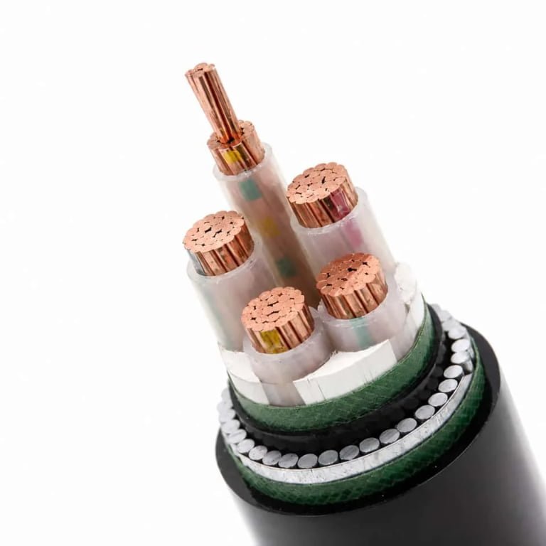
Specifying the wrong wire for a job — undersized conductors, wrong insulation class, mismatched voltage rating — doesn’t just create a code violation. It creates heat, and heat creates failures, and failures in the middle of a production shift create the kind of downtime that makes plant managers very unpopular very quickly. The financial exposure compounds fast: rewiring a machine cell after an insulation failure can run anywhere from a few hundred to several thousand dollars depending on access and cable routing, and that’s before you count lost output or scrapped product batches.
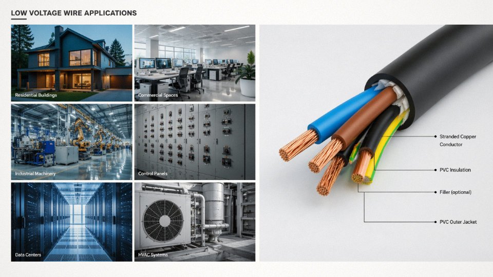
Low voltage wire, defined under IEC 60038 as cable rated for 50–1,000 V AC or 75–1,500 V DC, is used across building wiring, industrial machinery, automotive systems, renewable energy installations, instrumentation, and data infrastructure. It is the most widely deployed conductor category in the world, and selecting the right type — by conductor cross-section, insulation material, and installation environment — determines both safety and long-term operating cost.
What most buyers and specifiers don’t fully appreciate is just how wide that application range actually is, and how differently the same basic voltage class needs to be configured depending on whether it’s running through a conduit in a food-processing plant, buried under a solar field in a desert climate, or bundled inside a CNC cabinet where flexible stranding and oil-resistant jacketing matter enormously. The rest of this guide works through those use cases with enough specificity to actually help you make the right call.

Residential and Commercial Building Wiring: Load Types, Circuit Categories, and Code-Compliant Installation Practices
Building wiring is where low voltage wire specification gets messy fast. You are dealing with four distinct circuit categories under one roof, each with its own conductor sizing logic, insulation demand, and code jurisdiction — and getting any of them wrong means either a failed inspection or, worse, a smoldering junction box three years after handover.
The Four Circuit Categories and What They Actually Require
Branch circuits for lighting are the most common and, frankly, the most often undersized by cost-cutting contractors. In IEC markets, 2.5 mm² copper is the standard conductor for circuits up to 20 A, though in practice many designers in Europe and the Middle East will step up to 4 mm² on runs longer than 25 meters to keep voltage drop in check. In NEC markets, 12 AWG (roughly 3.3 mm²) handles your 20 A lighting branch circuits, while 14 AWG covers 15 A circuits where permitted by local amendments.
General-purpose receptacle circuits follow similar sizing but see more variable load profiles — a conference room outlet bank can sit idle for hours then suddenly carry laptop chargers, monitors, and a projector simultaneously. Small appliance circuits in kitchens and break rooms (the 20 A dedicated circuits required by NEC 210.11 and analogous IEC installation rules) need conductors rated for sustained load, not just peak draw. Dedicated appliance circuits for HVAC units, electric ranges, or elevator controls are sized individually to the nameplate load, often landing in the 6–16 mm² range depending on motor size and duty cycle.
Voltage Drop: The Constraint That Overrides Everything Else
Voltage drop discipline separates competent electrical designers from people who just pull numbers from a table. The working formula is straightforward:
V_drop = 2 × L × I × R / 1,000
where L is the one-way run length in meters, I is the load current in amperes, and R is the conductor resistance in mΩ/m. The factor of 2 accounts for the return conductor. The 3% maximum drop guideline for branch circuits — common across NEC, IEC 60364, and most national building codes derived from them — translates to roughly 7.2 V on a 240 V system. On a 120 V system that same 3% leaves you only 3.6 V of headroom, which is why long residential runs in North American construction often get bumped from 12 AWG to 10 AWG even when the breaker rating would technically permit the smaller wire.
Voltage drop limits in NEC are advisory (not mandatory) for branch circuits but become effectively mandatory when local code adoptions or AHJ interpretations enforce them as minimums.True
NEC 210.19(A) informational notes reference the 3% figure as a recommendation; however, many jurisdictions adopt this as enforceable through local amendments, and inspectors frequently cite it regardless.
Conduit Fill and Derating: Where Thermal Reality Bites
Running multiple conductors in conduit is standard practice, but the derating requirements in NEC Table 310.15(C)(1) — and IEC 60364-5-52 grouping correction factors — exist because bundled cables share heat. Four to six current-carrying conductors in a conduit triggers an 80% derating on allowable ampacity; nine or more drops you to 70%. In a commercial office fit-out with a high density of circuits in a single conduit run, ignoring this can push conductors into continuous operation above their rated temperature. The insulation degrades, becomes brittle, and fails on the first maintenance pull.
LSZH Wiring: Not a Premium Upsell, a Life-Safety Requirement
Hotels, hospitals, schools, and public transport terminals share one critical characteristic: high occupant density and limited evacuation time. In a corridor fire, conventional PVC insulation releases hydrogen chloride gas and dense black smoke — both of which kill people who might otherwise have escaped. LSZH (Low Smoke Zero Halogen) wire, tested to IEC 61034 for smoke density and IEC 60754-1/2 for halogen acid gas emission, is mandatory in these environments across most European, Middle Eastern, and increasingly Southeast Asian building codes. The smoke density test under IEC 61034 requires minimum 60% light transmittance — a threshold standard PVC compounds routinely fail.
Specifying LSZH adds roughly 15–35% to cable material cost depending on conductor cross-section and market conditions. That delta narrows considerably when you price in the liability exposure from a non-compliant installation in an occupied public building.
Data, Communications, and Signal Wiring in the Same Building
Cat6 UTP for structured cabling, BMS backbone loops, fire alarm wiring — all of these qualify as low voltage circuits but carry no meaningful power load. The separation matters in two ways. First, physical separation from power circuits is required (NEC Article 800, IEC 60364-4-44) to prevent induced noise and, in some fault scenarios, dangerous voltage transfer. Second, fire alarm loop topology — Class B (open circuit detection only) versus Class A (supervised loop that continues operating past a single fault) per NFPA 72 — dictates cable routing redundancy and affects both wire count and conduit design.
Class A loops require home-run return paths, which means roughly double the cable length compared to Class B daisy-chain layouts. That calculation has a real procurement impact on large hospital or airport projects.
Insulation Selection: PVC, XLPE, and LSZH Compared
| Insulation Type | Max Operating Temp | Relative Cost | Smoke Density (IEC 61034) | Typical Building Use |
|---|---|---|---|---|
| PVC | 70°C (standard) | Baseline (1.0×) | Fails (dense black smoke) | General commercial, industrial, low-rise residential |
| XLPE | 90°C continuous, 250°C short-circuit | 1.2–1.5× | Moderate, with halogens | High-load circuits, plant rooms, high-rise risers |
| LSZH | 70–90°C depending on compound | 1.15–1.35× | Passes (≥60% transmittance) | Hospitals, hotels, schools, transit hubs, data centers |
XLPE’s thermal advantage is real — the higher continuous rating means a given conductor cross-section carries more current without derating, which can allow downsizing one gauge step on heavily loaded circuits. Whether that saves money depends entirely on the ratio of material cost to labor and conduit cost at the specific project location. In markets where labor is expensive, the smaller conduit fill from thinner XLPE-insulated wire often justifies the premium over PVC even without the current capacity benefit.
Industrial Machinery and Factory Automation: Flexible Control Cables, Motor Leads, and VFD Wiring Challenges
Factory environments are genuinely hostile to wire and cable in ways that building wiring simply isn’t. You’re dealing with continuous motion, oil mist, vibration, chemical splash, and high-frequency electrical noise — often all at once, on the same cable run. Getting the construction wrong doesn’t just shorten cable life; it causes unplanned downtime, intermittent faults that are maddening to trace, and in VFD applications, premature motor winding failure.
Mechanical Stress: Flexing, Vibration, and Crush Loads
The hardest-working cables in any factory are those routed through cable carriers (drag chains). A cable in a high-cycle carrier on an injection molding machine or a CNC gantry may accumulate 5 to 10 million flex cycles over its service life — sometimes more, depending on stroke length and cycle rate. Standard stranding won’t survive this. IEC 60228 Class 5 fine stranding is the minimum for carrier applications; Class 6 (extra-fine bunched stranding) is preferable when torsional stress is also present, such as in robotic arm cables that twist as they flex. The difference in strand count between Class 2 and Class 6 for the same conductor cross-section is dramatic — a 1.5 mm² Class 6 conductor may use 30+ individual strands versus 7 for Class 2 — and that wire geometry directly determines how many cycles the conductor survives before fatigue cracking starts at the bend point.
Vibration from rotating machinery is a separate failure mode. Cables clamped too rigidly near a motor terminal box will work-harden at the clamp edge. Leaving a short free loop before the clamp entry — usually 1.5 to 2× the outer diameter, though plant practice varies — absorbs vibration without concentrating stress at one point.
Cable trays introduce crush loads, particularly when trays are overfilled, which happens more often than it should. Armored or braided constructions help, but honestly, the first fix is disciplined fill-ratio management.
Motor Lead and VFD Wiring
Direct-on-line motor connections are relatively forgiving — standard PVC-insulated copper cables sized correctly for the load, with appropriate derating for ambient temperature and grouping, work fine. VFD output wiring is a different problem entirely.
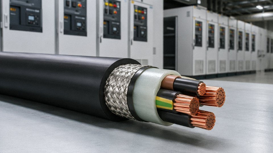
VFDs produce high-frequency switching transients on the output conductors. Common-mode voltage spikes can reach 1,000–1,600 V peak on 400 V drive systems, at switching frequencies between 2 and 16 kHz. Standard PVC insulation degrades under this stress, particularly on cable runs longer than roughly 20–30 m where the reflected wave effect amplifies peak voltage. For VFD applications, XLPE or EPR insulation with a symmetrical three-conductor-plus-earth construction and an overall copper braid shield is the correct specification. The shield should be bonded at both ends — drive cabinet and motor terminal box — to provide a low-impedance return path for high-frequency leakage current. Skipping the shield or bonding it at one end only will push that current back through the building earth grid, causing interference in PLCs and instrumentation nearby.
VFD output cables with XLPE insulation and full copper braid shielding significantly reduce common-mode voltage stress and extend motor winding insulation life compared to standard PVC cables on the same drive application.True
XLPE insulation has higher partial discharge resistance and dielectric strength than PVC at high switching frequencies, and symmetrical shielding reduces capacitive coupling of common-mode currents to motor windings — both mechanisms are documented in IEC 60034-25 and widely referenced in drive manufacturer installation guides.
Sizing a motor supply cable — a worked example. Take a 37 kW, 400 V, three-phase motor with a full-load current of roughly 70 A (depending on power factor and efficiency class — check the nameplate). Starting current with a DOL starter runs 6–8× FLC, so 420–560 A for a few seconds. The cable doesn’t need to be sized for starting current in most cases; the protective device handles that. You size for continuous FLC plus derating. In a 40°C ambient with cables grouped in a tray, a 16 mm² copper cable is often borderline; 25 mm² gives comfortable headroom and a lower volt-drop over runs beyond 30 m. For a VFD-fed version of the same motor with a 50 m cable run, add shielded VFD cable in 25 mm² and verify the drive manufacturer’s maximum cable length specification — some 37 kW drives derate allowable cable length significantly above 40°C.
Control Cable and EMI Shielding
PLC I/O wiring, sensor cables, and fieldbus trunks need shielding in any environment with VFDs, contactors, or high-current switching nearby. The shielding specification matters more than most procurement specs acknowledge. An 85% braid coverage is standard and adequate for moderate noise environments. For installations near multiple large VFDs or in heavy machining centers, specifying 100% foil plus braid construction — the foil closes the gaps the braid leaves, the braid provides mechanical strength and low-impedance bonding — makes a measurable difference in noise rejection. Individually shielded pairs inside an overall shielded multicore cable give the best performance for mixed analog/digital signal bundles, because each pair’s shield breaks the capacitive coupling between channels.
Jacket Compounds for Chemical and Thermal Resistance
Machining centers flood parts with coolant. Chemical processing plants have their own list of aggressive fluids. PVC jackets soften in oils and certain cutting fluids over time, eventually cracking under flex stress. Polyurethane (PUR) handles most coolants and many oils well, stays flexible down to −40°C, and tolerates continuous service to around +90°C — better flex-fatigue life than PVC in carriers too. TPE jackets are a reasonable middle ground where cost is a constraint. Neoprene holds up to ozone and moderate chemical exposure but is stiffer in cold environments; it’s common on welding cable and outdoor motor leads where UV and ozone resistance matter more than low-temperature flexibility.
One practical point: always verify the specific chemical compatibility of the jacket compound against the actual fluid, not just the generic category. “Coolant resistant” covers a wide range, and some synthetic coolant additives attack PUR just as aggressively as they attack PVC.
Bend Radius and Cable Management
Minimum bend radius for flexible cables in carriers is typically 7.5× outer diameter during dynamic operation — some manufacturers specify 10× for long-life applications above 3 million cycles. Violating this during installation, or designing a carrier with too tight a radius for the cable selected, is one of the most common causes of premature carrier cable failure in my experience. The cable looks fine initially; failure shows up 6–18 months in as intermittent continuity faults or insulation breakdown at the bend point. Specify the cable OD and minimum bend radius together when designing the carrier system, not after the carrier is already on order.
Solar PV Systems and Energy Storage: DC Low Voltage Wiring from Array to Inverter
Solar installations sit in an interesting gray zone for cable engineers. Residential string inverters typically run at 150–600V DC. Utility-scale tracker arrays can push string voltages to 1,500V DC, which lands exactly at the upper boundary of standard IEC low voltage classification — or fractionally beyond it, depending on how your national standards body interprets IEC 60038. At 1,500V DC you need cables rated to 1.5 kV, and not every yard of “low voltage cable” stock qualifies. Get this wrong during procurement and you’re either field-rejecting cable on commissioning day or, worse, running undersized insulation that degrades in three years instead of twenty-five.
DC Arc Faults: The Risk That Doesn’t Reset Itself
AC systems have a natural safety valve: the sine wave crosses zero 100 or 120 times per second, and an arc usually extinguishes at that crossing. DC has no such crossing. A sustained DC arc in a PV string can burn at temperatures above 3,000°C and maintain itself on carbonized insulation, connector plating, or even corroded aluminum terminations. It’s the primary fire cause in rooftop PV installations, and it’s almost always traceable to one of three root causes: insulation that’s been mechanically abraded by a roof edge or cable tie, a connector crimped with the wrong die, or a terminal not torqued to spec.
This is why insulation quality in PV wire isn’t a marketing differentiator — it’s a fire prevention specification. Double insulation (two concentric layers, each a minimum 0.8 mm wall per IEC 62930) means that if the outer layer is damaged, there’s still a functional barrier. Cross-linked polyethylene (XLPE) or ethylene propylene rubber (EPR) are the materials of choice; both resist UV degradation, ozone cracking, and the thermal cycling that comes from baking in the sun all day and cooling overnight. Temperature ratings should be 90°C continuous, 120°C peak — standard PVC simply can’t tolerate the roof surface temperatures seen in southern climates during summer.
PV cables certified to IEC 62930 must pass UV aging tests equivalent to roughly 25 years of outdoor exposure before certification is granted.True
IEC 62930 includes accelerated UV aging (xenon arc lamp) and thermal aging tests designed to simulate long-term outdoor service life, validating the claim of extended durability under combined UV and thermal stress.
Cross-Section Sizing: Working Backward from Acceptable Loss
For string wiring, most designers target a maximum 1–2% resistive power loss over the DC run. On a 50-meter single-conductor run at 10A string current (fairly typical for residential), hitting a 1% loss limit with a 600V string voltage means you need roughly 4–6 mm² copper. Push the run to 80 meters, or if it’s a commercial combiner with 15–20A per string, you’re looking at 10–16 mm². These aren’t arbitrary catalog numbers — they come out of straightforward voltage-drop calculations, but a lot of installers skip the math and default to 4 mm² everywhere. The result is acceptable efficiency loss on short runs, measurable degradation on long ones, and occasionally a connector running warm enough to accelerate oxidation.
Battery Storage Interconnects: Short Runs, High Consequences
BESS DC bus wiring — whether a 48V residential lithium system or a 400V commercial rack — is almost the opposite problem. Runs are short (sometimes under a meter), but currents are very high, sometimes 200–500A depending on the battery bank capacity and inverter rating. At those current levels, a slightly loose terminal or an oxidized copper surface creates a resistive joint that heats up during every discharge cycle. Anti-oxidant compound on bare copper terminations is standard practice in any well-run battery installation. Cable cross-sections here are typically 35–120 mm², and the mechanical routing has to avoid tight bends that stress the conductor.
Certifications Worth Demanding
Three marks matter for PV DC cable procurement:
| Certification | What It Actually Tests |
|---|---|
| TÜV 2 PfG 1169 / EN 50618 | UV aging, heat aging, oil resistance, flame behavior, mechanical abuse (abrasion, bend cycles) |
| UL 4703 | US market — sunlight resistance, wet/dry insulation resistance, crush and impact resistance |
| IEC 62930 | International — harmonizes with EN 50618, adds ozone resistance, cold bend, and dimensional checks on insulation wall thickness |
TÜV 2 PfG 1169 is the legacy German testing spec that most European EPCs still require by habit, even though EN 50618 is the current standard. They’re closely aligned, but if your customer specifies one, don’t assume the other automatically satisfies the requirement — confirm with the test lab report. UL 4703 is mandatory for US utility interconnects; no certification means no AHJ approval in most jurisdictions.
In practice, any PV cable from a credible manufacturer should carry at least two of these three marks. If a supplier can only produce a TÜV certificate dated more than five years ago and can’t provide a current test report, that’s a flag worth taking seriously before signing a volume purchase order.
Automotive, Rail, and Marine Wiring Harnesses: Low Voltage Wire Under Vibration, Moisture, and Chemical Attack
Transport wiring is a different discipline from building wiring, and engineers who treat it as the same category tend to find out the hard way — usually during a warranty claim or a classification society audit. The voltages are nominally modest: 12V systems in conventional passenger vehicles, 24V in heavy trucks and buses, and the increasingly common 48V mild hybrid architecture that’s now standard across much of the European and Asian light vehicle market. But the operating environment is brutal in ways that a fixed building installation never faces.
Automotive Standards and Why They Aren’t Interchangeable
ISO 6722, SAE J1128, and JASO D611 each govern automotive low voltage wire, and they aren’t equivalent documents you can substitute freely. ISO 6722 covers single-core cables up to 60V and specifies conductor construction, insulation thickness, and abrasion resistance using a scrape test that cycles a weighted blade across the insulation until breakthrough — a test that exposes how quickly cheap PVC compounds fail under repeated contact with a sharp edge. SAE J1128 is the North American benchmark and includes its own elongation and cold-bend tests at −40°C. JASO D611 applies to Japanese-market vehicles and adds stricter requirements around heat-aging dimensional change. If you’re supplying harness wire into a Tier 1 supplier building for multiple OEM markets simultaneously, you often need a cable that passes all three. That’s not always straightforward to source.
Failure Modes That Don’t Appear in Building Wire Failure Analysis
Fretting corrosion at terminals is the failure mode that catches people off-guard. A vehicle chassis vibrates continuously — engine mounts isolate some of it, but harness connectors still see micro-movement, and at tin-to-tin or tin-to-copper contact interfaces that slight reciprocal sliding disrupts the oxide film and generates resistive debris. Terminal resistance climbs, voltage drop increases, and sensor signals become unreliable before anything looks physically wrong. The fix is tinned conductors combined with sealed, positive-retention connectors and, where vibration is severe (near the engine or transmission), strain relief boots that reduce relative motion at the terminal.
Insulation chafing against sheet metal is similarly insidious. Harnesses routed through body panels rely on corrugated conduit and grommets, but if a grommet shifts or a clip breaks, the insulation contacts a metal edge and abrades through in weeks. PTFE or ETFE insulation resists this far better than standard PVC — wall thickness can be thinner for equivalent abrasion resistance, which matters in confined routing channels — though both materials cost meaningfully more and require different tooling for crimping.
Rail Cable: When Fire Behavior Becomes the Primary Specification Driver
Rail wiring under EN 50306 operates in enclosed passenger spaces, which changes the priority order entirely. Low smoke, zero halogen, and fire-retardant performance aren’t optional upgrades — they’re baseline requirements, because toxic fume generation during a fire in a tunnel is a life-safety issue with regulatory and legal consequences. Rail cables also have to survive 125°C continuous operating temperature (higher than most automotive wire) and pass fluid immersion tests in diesel, hydraulic fluid, and cleaning agents. XLPE and LSZH compound insulations dominate here. Flexibility at low temperatures matters too, since rolling stock in northern European and northern Asian routes sees platform ambient temperatures well below −20°C during maintenance and coupling operations.
Marine Low Voltage Wiring: Corrosion Is the Enemy, Full Stop
IEC 60092-353 and classification society rules from Lloyd’s Register, DNV, and Bureau Veritas converge on one consistent theme: tinned copper conductors are essentially mandatory for anything that will live in a marine environment. Bare copper in salt-air bilge spaces corrodes fast enough to cause measurable resistance increase within a few years. Moisture-resistant insulation, proper bundling with adequate derating (bilge spaces trap heat; a bundle of 10 cables in a confined tray may need to be derated by 30–40% depending on ambient temperature and bundle diameter), and watertight penetration fittings through bulkheads are all non-negotiable for a vessel that needs to pass survey.
Tinned copper conductors are required by IEC 60092-353 for marine low voltage cablesTrue
IEC 60092-353 specifies tinned copper conductors for shipboard cables to prevent corrosion in the humid, salt-laden environments typical of marine installations. Classification societies including DNV and Lloyd's Register enforce this in their rules for electrical installations on vessels.
Mixed-metal connections — aluminum terminal lugs on copper conductors, for example — create galvanic corrosion potential in the presence of any moisture. In marine wiring this is a chronic maintenance issue, and the practical answer is to avoid mixed metals wherever possible or use bi-metallic crimp sleeves rated for the exposure class.
Harness Manufacturing Details That Affect Procurement
Conductor cross-sections in a typical vehicle harness span an enormous range: signal wires for CAN bus or sensor circuits run as small as 0.35 mm², while starter motor and main battery cables reach 50–70 mm² in heavy vehicles. Color coding follows DIN 72551 in European automotive applications and SAE J1128 in North American ones — these are not compatible systems, and sourcing the wrong color convention for a given OEM program creates assembly errors that are expensive to correct mid-production. Laser-marked alphanumeric identification on wire jackets has largely replaced hand-tagging in modern harness plants because it survives fluid exposure and is readable after years of service, which matters when a technician is tracing a fault in a 15-year-old bus.
Insulation Material Comparison for Transport Low Voltage Wire
| Insulation | Typical Temp Rating | Flexibility at −40°C | Chemical Resistance | Relative Cost |
|---|---|---|---|---|
| PVC | 70–105°C depending on compound | Stiffens significantly; some grades crack | Moderate; degrades in fuel/oils | Lowest |
| XLPE | 90–125°C | Good; retains flexibility | Good; better than PVC in hydrocarbons | Moderate |
| ETFE | 150–175°C | Excellent | Excellent; resists most fuels, acids | High |
| Silicone | 180–200°C | Outstanding; stays flexible | Good general, poor in fuel/oils | High to very high |
The choice isn’t simply “use the best material.” Silicone’s outstanding low-temperature flexibility makes it attractive for Arctic rail applications, but its mechanical softness means it abrades easily against hard edges — which is exactly the failure mode you’re trying to avoid in a vehicle harness. ETFE hits a useful balance of abrasion resistance, temperature range, and chemical resistance for underhood automotive and demanding rail applications, but at a price premium that needs to be justified against the service environment. PVC remains the volume workhorse for interior body harnesses where temperatures are moderate and fluid exposure is limited.
Outdoor Infrastructure, Street Lighting, and Underground Distribution: Burial-Rated and Armored Low Voltage Cable Selection
Underground low voltage cable fails quietly. You don’t get warning signs the way you do with a tripped breaker or a burning motor. The fault develops over years — moisture ingress at a poorly made joint, a slow crush from a shifted pavement slab, a PVC sheath that’s been chemically softened by contaminated fill — and then one day a section of street lighting goes dark or a distribution circuit drops under load. Getting the cable selection right from the start is much cheaper than excavating a buried run five years later.
Direct Burial Versus Conduit Systems
The first decision is whether to lay cable directly in the ground or pull it through a buried duct or conduit. Direct burial cables require a mechanically robust outer sheath — LLDPE or HDPE compounds per IEC 60502-1 are the sensible choice, offering better resistance to soil stress, root penetration, and moisture absorption than standard PVC. PVC outer sheaths are technically permitted but they soften at elevated soil temperatures and become brittle in cold climates, so in practice they’re a compromise you make when budget is tight and conditions are benign.
Duct systems cost more upfront — HDPE corrugated ducts, draw-in boxes, sealing glands — but they make future upgrades and fault location dramatically easier. In high-traffic zones (under roads carrying vehicles over roughly 10–15 tonnes axle load), most standards and local regulations push you toward duct-and-cable systems anyway, with minimum cover depths typically in the range of 600 mm to 1,000 mm depending on jurisdiction and traffic classification. Direct burial in pedestrian or green-field areas might sit at 450–600 mm, but always verify against the local civil specification — these depths vary more than you’d expect between countries.
Armouring: Matching the Mechanical Threat to the Construction
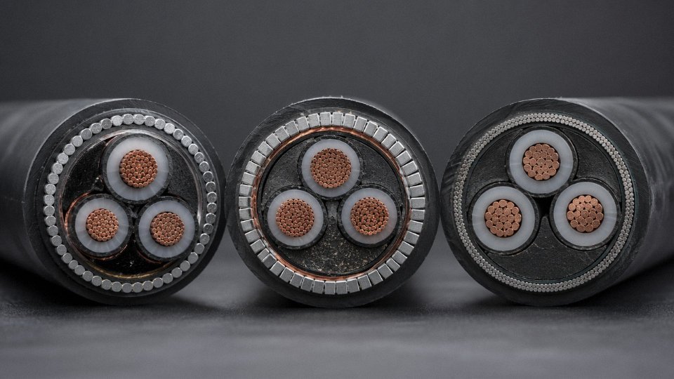
Steel wire armoured (SWA) cable is the default for direct burial multi-core runs where tensile load during installation is a concern — pulling a heavy cable through a long trench, or laying on a slope. The helically applied steel wires handle longitudinal pull reasonably well. Steel tape armoured (STA) construction, by contrast, is better suited to radial crush protection; the overlapping steel tapes resist point loads from stones or compaction equipment but offer limited tensile strength. For single-core cables in large conductor sizes — say, 150 mm² or 240 mm² — aluminum wire armoured (AWA) is the correct choice. Steel armouring on a single-core cable creates a magnetic circuit that generates significant eddy current losses under AC load; aluminum breaks that loop without meaningfully sacrificing mechanical protection.
Corrosion and Soil Aggressiveness
Soils contaminated with industrial runoff, high sulfate content, or acidic organics (peat, for instance) attack PVC outer sheaths over time, eventually reaching the armouring and causing corrosion. Polyethylene outer sheaths perform significantly better in these environments. IEC 60811 sets out the test series for sheath compound quality — heat ageing, elongation at break, oil resistance, cold bend — and it’s worth requiring full IEC 60811 compliance documentation from your supplier rather than accepting a general product datasheet, particularly for cables going into chemically aggressive ground.
PE outer sheaths outperform PVC outer sheaths in acidic or contaminated soils for underground cable installationsTrue
Polyethylene has lower water absorption, better chemical resistance, and maintains mechanical properties across a wider temperature range than PVC, making it more suitable for aggressive soil environments per IEC 60502-1 guidance and practical installation experience.
Street Lighting Circuits
Street lighting low voltage distribution is a specific-use case that gets underspecified more often than it should. Loop-through systems — where each lantern column is connected in sequence along a single circuit — typically run 2.5 mm² or 4 mm² twin-and-earth cables, sized not just for load current but for voltage drop across what can be a long loop. The switching duty matters too: these circuits can switch on and off daily for 20+ years, which means the insulation sees thermal cycling that PVC handles less gracefully than XLPE. Near district heating pipe runs, where soil temperatures can reach 50°C or occasionally higher, XLPE-insulated cable is essentially mandatory — PVC insulation rated at 70°C conductor temperature gives you almost no thermal margin in those conditions.
Joint Quality Is Where Underground Circuits Actually Fail
This is the single most important point in underground cable reliability, and it’s consistently underweighted in procurement decisions. Heat-shrink joint kits, cold-applied resin-filled joints, and push-on separable connectors are the main options at low voltage, and each has appropriate conditions. Heat-shrink joints are widely used and generally reliable when installed correctly in dry conditions; resin-filled joints provide excellent moisture sealing in wet or submerged environments but require correct resin mixing and cure time. In practice, site joints are often made by contractors under time pressure, in a muddy trench, without proper drying. Require jointing kits from manufacturers who provide third-party qualified documentation, and specify that joint records (location, kit type, installer) are submitted as part of project handover.
Submarine and Shallow-Water Installations
For inter-island distribution or shore-to-offshore platform links in relatively shallow water — up to perhaps 50–100 m — standard SWA cable is insufficient. Double-SWA armouring handles the mechanical loads from seabed current and installation tension. A lead sheath water barrier beneath the armouring is necessary if any long-term water exclusion from the insulation is required. Teredo worms are a genuine threat to organic and some polymer sheaths in warmer coastal waters; anti-teredo compound impregnation or a purpose-designed outer serving is not an optional extra in those environments. Cable route surveys, burial depth requirements under shipping lanes, and sacrificial anode systems on steel structures nearby all interact with the cable specification in ways that are worth resolving before procurement rather than after the cable is already on the drum.
Telecom, Security, and Building Automation Low Voltage Signal Wiring: When Voltage Is Low but Data Integrity Is Critical
Most engineers working in power distribution think of low voltage wire in terms of current-carrying capacity — cross-section, temperature rating, derating factors. That mental model breaks down completely once you move into signal wiring. In CCTV backbones, BACnet trunk cables, Profibus fieldbus runs, and fire alarm loops, the conductor might be 0.22 mm² or 0.5 mm² not because the current demands it, but because the geometry needs to be right. Ampacity is almost irrelevant. Impedance, capacitance per meter, and mutual inductance are what govern whether your system works.
Signal Integrity, Not Ampacity, Drives Cross-Section Choice
A typical IP camera on a coaxial run draws maybe 150–300 mA. You could theoretically carry that on wire sized for a doorbell. But RG-59 and RG-6 coaxial cables are specified at 75 Ω characteristic impedance because analog video and IP-over-coax protocols are designed around that value. Deviate from it — substitute a cheaper coax with the wrong dielectric constant or an out-of-spec center conductor diameter — and you introduce impedance mismatches that reflect signal energy back toward the source. In analog CCTV that shows up as ghosting. In HD-over-coax systems like HDCVI or TVI, it degrades the bit error rate enough to cause frame drops, especially over runs approaching 300–400 m.
Structured data cabling for IP cameras is specified at 100 Ω (±15%) per TIA-568 and ISO/IEC 11801. The capacitance limit — typically 5.6 nF per 100 m for Cat5e, tighter for Cat6A — is there to control signal attenuation at high frequencies. A cable manufacturer who skimps on the insulation wall thickness to reduce material cost will blow that capacitance spec. The cable tests fine at DC. It fails at 250 MHz.
Industrial Fieldbus Cable: The Parameters Actually Matter
Profibus DP Type A cable — the one you should use for any run over roughly 100 m or above 1.5 Mbit/s — specifies 150 Ω ±15% characteristic impedance and a capacitance ceiling of 30 pF/m. Those numbers are not suggestions. Exceed the capacitance limit and you reduce the maximum segment length; mix in a length of generic shielded twisted-pair and the impedance discontinuity causes reflections that manifest as intermittent CRC errors. In a plant running batch processes, an intermittent CRC fault on a Profibus segment can trigger spurious drive trips that are nearly impossible to reproduce during maintenance windows. I’ve seen facilities spend weeks troubleshooting what turned out to be 40 m of wrong cable spliced into a 200 m segment during a rushed site expansion.
Modbus RS-485 is more tolerant, but “more tolerant” is not the same as “anything goes.” The EIA-485 standard calls for a cable with characteristic impedance in the 100–120 Ω range. FOUNDATION Fieldbus H1 has its own Type A specification: 100 Ω ±20%, attenuation under 3 dB/km at 39 kHz. These are different cables, and you cannot treat them as interchangeable even though they look similar in the field.
PoE Bundling: The Thermal Problem Nobody Talks About
IEEE 802.3bt Type 4 (PoE++) puts up to 90 W down a single Cat6 or Cat6A cable. That’s manageable for a single cable in free air. Bundle 24 or 48 of those cables in a conduit or cable tray — common in a large commercial security or BMS installation — and the mutual heating becomes a real derating concern. The key electrical parameter is conductor resistance balance between pairs within the same cable. If one pair has measurably higher resistance than its partner, current distributes unevenly, one pair runs hotter, and over time you get insulation degradation at the bundle center. TIA-568-C.2-1 tightened the resistance unbalance limit specifically because of PoE bundling failures. Specify cables that meet those limits; don’t assume all Cat6A is equivalent.
IEEE 802.3bt Type 4 PoE can deliver up to 90W over compliant Cat6 or Cat6A cableTrue
IEEE 802.3bt (published 2018) defines Type 3 at 60W and Type 4 at 90W PSE output over four-pair Cat6/Cat6A; this is confirmed in the standard and widely documented by switch and midspan manufacturers.
Security System Wiring: Loop Resistance and Run Length Are Hard Limits
Intrusion detection panels operating at Grade 3 per EN 50131 typically specify a maximum end-of-line resistance of around 100 Ω for detector loops. That limit exists because the panel measures loop current to distinguish between a normal state, an alarm, a tamper, and a fault — and excessive resistance compresses that measurement window until states become ambiguous. For a 0.5 mm² copper conductor (roughly 36 Ω/km), you’re looking at a maximum loop length of around 1,400 m total, accounting for both the outward and return conductors. Use 0.75 mm² and you roughly double that. Getting this calculation wrong on a large perimeter system means either false faults or genuine alarms that the panel cannot classify.
Wiegand access control readers have tighter constraints than most installers expect. The data lines are unshielded in most installations, which makes them susceptible to interference from parallel power runs. Maximum practical run lengths are usually 150–200 m using 22 AWG (0.34 mm²) twisted conductors, though some controllers specify less. Running Wiegand data alongside 230 V lighting circuits in the same conduit — which happens in rushed fit-outs — causes enough induced noise to corrupt card reads.
LVD Scope and the EMC Obligation That Replaces It
Signal cables operating below 50 V AC fall outside the scope of the EU Low Voltage Directive 2014/35/EU. That can create a false sense of regulatory freedom. Those same cables must still comply with the EMC Directive 2014/30/EU, which means they need to neither emit interference nor be unduly susceptible to it. In life-safety circuits — fire alarm wiring, emergency voice evacuation systems — EN 50200 circuit integrity requirements apply regardless of operating voltage. A fire alarm cable that loses circuit continuity at 300 °C for 30 minutes is not a compliance detail; it is the reason people can evacuate a building. Specifying standard PVC-insulated signal cable in a fire alarm backbone to save a few cents per meter is one of those decisions that looks fine until it isn’t.
How to Read a Low Voltage Wire Specification Sheet: Conductor Size, Insulation Thickness, Ampacity Tables, and Quality Marks
A specification sheet looks straightforward until you’ve received a delivery that doesn’t match it. Understanding what each field actually commits the manufacturer to — and what it leaves vague — is the difference between a smooth commissioning and a costly re-pull.
What the Conductor Fields Really Mean
Take a standard 4-core 10 mm² XLPE/SWA/PVC cable as a working example. The “10 mm²” figure is a nominal cross-section, not a guaranteed minimum area. What IEC 60228 Class 2 actually controls is the maximum DC resistance of the conductor: for a 10 mm² copper conductor, that’s 1.83 Ω/km at 20°C. A conductor 8–12% undersized in actual cross-section can still pass a casual visual check but will show elevated resistance immediately on a simple Wheatstone bridge or digital micro-ohmmeter test. This is one of the most documented forms of cable fraud in international procurement, and it’s caught in about ten minutes with a resistance test and a 100-meter sample.
The insulation thickness field in IEC 60502-1 lists a nominal value and a minimum permissible value — typically the nominal minus roughly 0.1 mm or 10%, whichever is greater. Both numbers matter. A supplier quoting “nominal 2.5 mm XLPE” while consistently extruding at 2.2 mm is technically in breach once that minimum is exceeded, but you won’t know unless you cut a cross-section and measure with a calibrated micrometer at multiple clock positions. Bedding thickness, armour wire diameter, and outer sheath thickness follow the same pattern: each has a minimum, and each is a place where cost-cutting leaves a measurable trace.
Resistance at 20°C vs. Operating Temperature — Don’t Derate Twice
The conductor resistance printed on the datasheet is at 20°C. At 90°C (the rated maximum conductor temperature for XLPE), resistance rises by roughly 30–32%, which directly affects voltage drop under load. Here’s where engineers sometimes make an error: IEC 60502-1 ampacity tables already incorporate the maximum operating temperature. The table value for 10 mm² copper in free air under a specific installation method already assumes the conductor is running at 90°C continuously. If you then apply an additional thermal correction factor because you’re worried about temperature, you’re derating twice, and you’ll end up oversizing unnecessarily. Apply temperature correction only when the ambient temperature at the installation site differs from the table reference (typically 30°C for in-air, 20°C for buried).
Using Ampacity Tables Without Creating New Problems
IEC 60502-1 ampacity reference tables require you to identify three things before reading a value: installation method (buried direct, in a duct, clipped in free air, on a tray), number of circuits grouped together, and ambient temperature. Grouping derating for a bundle of six circuits touching each other in a tray runs roughly 0.57–0.67 of the single-cable value, depending on arrangement — that’s a significant reduction that gets missed in quick estimates. For circuits feeding variable speed drives or other nonlinear loads with total harmonic distortion above about 15%, a harmonic derating factor applies to account for additional neutral conductor heating in four-core cables. Skipping that step on a large VFD panel feed is how you get nuisance tripping six months after handover.
What Third-Party Marks Actually Certify
KEMA, CESI, and similar body type-test reports confirm that one specific cable construction — exact materials, exact dimensions — was tested and passed IEC requirements at a point in time. They say nothing about what’s on today’s production reel. Factory Production Control audits (ongoing surveillance visits, not one-time events) are what bridge that gap. Buyers on international projects should request both: the type test report with the exact cable construction matching their purchase order, and evidence of current FPC audit status. A type test on a 16 mm² cable doesn’t cover your 10 mm² order.
Conductor cross-sections 8–15% below nominal are a documented problem in international cable procurementTrue
Multiple independent studies and customs inspection programs in the EU, Middle East, and Southeast Asia have identified underweight conductors in low-voltage cable shipments, particularly from unaudited manufacturers. IEC 60228 controls maximum resistance rather than minimum physical cross-section, making resistance measurement the reliable detection method.
Red Flags in a Quotation — and How Incoming Inspection Catches Them
PVC masquerading as XLPE is harder to detect by eye than you’d expect, especially with a freshly extruded black sheath. The giveaway is usually a cross-section cut: XLPE has a slightly waxy, translucent appearance when cut cleanly; PVC tends to be more matte and deforms more under knife pressure. A simple hot-wire test (the insulation won’t drip or flow if it’s genuinely cross-linked) gives a fast field indication. Armour wire diameter below the specified minimum shows up on a micrometer in seconds. Missing or clearly templated test reports — where the cable description doesn’t precisely match the ordered spec — are a straightforward disqualifier.
Jinda’s production process runs conductor resistance testing on 100% of output, with spark testing at 8 kV across all LV insulation as a routine line check. Type tests under IEC 60502-1 are conducted with third-party witness, and the test reports reference the exact construction — conductor class, insulation compound grade, armour wire dimensions — that appears on the order documentation. For procurement managers managing projects across multiple time zones, that traceability is worth more than a price that’s suspiciously low.
Frequently Asked Questions About Low Voltage Wire Applications
Can I use the same low voltage wire indoors and outdoors?
Not without checking the sheath compound first. Indoor-rated PVC cables — the kind you’d pull through conduit inside a commercial building — typically lack UV stabilization. Six months of direct sunlight will chalk, crack, and eventually embrittle the outer jacket, and moisture ingress follows. Outdoor-rated cables carry UV-resistant PE or HDPE outer sheaths, and direct-burial types add an additional protection layer. The designation you want is on the drum label: something like “PVC/UV” or simply “PE sheath, outdoor rated” per IEC 60502-1. If the label doesn’t explicitly state UV resistance or outdoor suitability, assume it isn’t.
A sheathing compound swap sounds minor, but the failure mode is not. A cracked outdoor sheath in a wet climate can pull ground-fault current for months before a nuisance trip reveals the damage — by which point the conductor itself may be corroded at splice points.
What is the maximum run length before voltage drop becomes a problem?
This depends entirely on your load current, supply voltage, conductor cross-section, and what percentage drop your equipment or code will tolerate. As a working example: a 230 V single-phase circuit carrying 10 A with a 3% maximum permissible drop limits a 2.5 mm² copper run to roughly 75–85 meters one-way (the exact figure shifts with conductor temperature and the resistivity value you use). Step up to 4 mm² and that limit extends to around 120–130 meters.
The practical fix beyond that isn’t always upsizing the cable for the full run — sometimes a local sub-distribution panel or a 400 V distribution spine with step-down at the load end is cheaper, especially in large factory buildings or outdoor lighting circuits over 200 meters.
Is “low voltage wire” the same as “low voltage cable”?
In everyday procurement conversations, people use them interchangeably, and suppliers understand either term. Technically: a wire is a single insulated conductor; a cable is an assembly of multiple conductors with an overall sheath and, in some constructions, armouring. Both fall under the same voltage classification under IEC 60038 — 50 V to 1,000 V AC, 75 V to 1,500 V DC. The distinction matters when you’re writing a specification, because “supply low voltage wire” on a purchase order could legally be satisfied with single-core product when you actually needed a multicore armoured cable.
Can standard 0.6/1 kV cable handle solar DC systems above 600 V DC?
Borderline, and in practice, no — not without a specific DC voltage certification. A standard 0.6/1 kV cable is rated 1,000 V AC, but DC withstand is a different test regime. DC doesn’t have a zero-crossing, so arc extinction is far more difficult, and partial discharge behavior in insulation differs under sustained DC stress. For 1,000–1,500 V DC PV string circuits, cables must be tested and certified specifically under IEC 62930 or UL 4703. Using a standard building cable in a 1,500 V DC string because it “passes the voltage number” is a genuine fire risk.
Standard 0.6/1 kV rated cable is safe for use in 1,500 V DC solar PV string wiringFalse
DC withstand requirements differ fundamentally from AC ratings. IEC 62930 and UL 4703 require specific DC voltage certification; arc behavior under sustained DC stress is more severe than AC, and standard building cable is not rated or tested for this application.
What does LSZH (or LSOH) cable mean, and when is it required?
Low Smoke Zero Halogen — the insulation and sheath compounds are halogen-free, so when burned they emit minimal toxic, corrosive gas and dramatically less opaque smoke compared to standard PVC. In a metro tunnel or hospital corridor, that difference is not academic; smoke opacity is a primary cause of evacuation failure in fires. LSZH is mandated by code or regulation in tunnels, underground rail, hospitals, high-rise escape routes, and certain offshore platforms across most European and many Asian jurisdictions. Performance is tested per IEC 60754 (acid gas emission) and IEC 61034 (smoke density). Worth noting: LSZH compounds are generally less flexible and slightly more expensive, so specifying them everywhere in a standard industrial building is over-engineering.
How do I verify a supplier’s cable actually meets the IEC standard printed on the drum?
Request the third-party type test report, issued by an ILAC-accredited laboratory, and confirm the tested construction — conductor cross-section, insulation thickness, sheath compound — matches the product you’re actually ordering. That last check trips people up; a valid test report on 25 mm² cable tells you nothing about the 10 mm² product from the same line if it wasn’t independently tested.
On incoming goods, a calibrated micrometer measuring insulation and sheath wall thickness against IEC 60502-1 tables costs almost nothing and catches the most common shortcut in low-cost cable production: undersized insulation walls. Conductor resistance per IEC 60228 is equally quick with a bridge meter. Jinda supplies full type test documentation and material test certificates as standard on international orders.
What cross-section is needed for a 50 kW three-phase load at 400 V over a 100-meter run?
Full load current at unity power factor runs roughly 72 A (real loads with 0.85 power factor push that closer to 85 A, which changes everything). Starting at 70 mm² as a conservative anchor, calculate voltage drop at 100 m — typically acceptable — then apply grouping derating if cables are bundled, ambient temperature correction if the route runs through a hot switchroom, and installation method factor if it’s in conduit versus on a tray. Working through those, most installations land on 35 mm² or 50 mm² copper XLPE depending on conditions. Aluminum at 50 mm² or 70 mm² is a legitimate cost option if your termination hardware and local code allow it. Always validate against your jurisdiction’s ampacity tables, not just the voltage drop calculation — sometimes thermal limits govern before voltage drop does.
Sourcing Low Voltage Wire for International Projects: What Global Buyers Should Demand from a Supplier
International LV cable procurement goes wrong in predictable ways: a supplier passes the paper audit, ships the first container on spec, then delivers inconsistent batches once the project is locked in. Protecting against that requires evaluating suppliers against criteria that actually predict performance — not just what’s on a certificate.
The Five Criteria That Actually Matter
Production capacity aligned to your project volume. A supplier running at 95% capacity cannot absorb a rush delivery or a batch rejection without pushing your schedule. Ask for annual output figures and, more usefully, the capacity of the specific extrusion line your cable requires. A project drawing 800–1,200 km of 4 mm² NYY in six months needs a different supplier profile than a 20-drum spot buy.
Third-party certified quality management. ISO 9001 is the floor, not the ceiling. ISO 14001 matters increasingly for European and Australian government projects where environmental compliance is a tender requirement. Ask for the most recent surveillance audit report, not just the certificate — the certificate tells you the system exists; the audit report tells you whether it’s functioning.
Accredited type test reports under your market’s governing standard. This is where a lot of Asian cable gets disqualified at the port or on the engineer’s desk. A cable sold into the Middle East typically needs SASO or SABER compliance; Australia requires compliance with AS/NZS 5000 series; European projects generally want IEC 60502 type tests from an accredited laboratory like KEMA, CESI, or ASTA. A test report from the manufacturer’s in-house lab is not the same thing. Confirm the test house, the report date, and whether the tested sample matches the construction you’re actually buying — conductor cross-section, insulation compound, sheath thickness, and armouring type all need to match.
Regional track record. A supplier who has exported to your country or project region before has already navigated the customs documentation, the marking requirements, and the typical specification deviations that local engineers ask for. This sounds soft, but it translates directly into fewer hold-ups at customs and fewer RFI cycles during commissioning.
Responsive pre-sales technical support. If it takes four days to get a dimensional tolerance confirmed, that supplier will not be fast when you have a site query at 11 p.m. before a concrete pour.
Why Vertical Integration Changes the Batch-to-Batch Story
A trading company assembling orders from three or four sub-contractors can match a price, but it cannot control conductor stranding lay length, insulation compound lot consistency, or the tension during armouring. Each handoff is a variation point. A vertically integrated manufacturer drawing its own copper rod, stranding conductors in-house, running its own extrusion lines for insulation and sheathing, and armouring on-site can trace a quality deviation back to a single shift on a single machine. In practice, that means fewer surprises across a multi-shipment project.
What a Credible Technical Proposal Looks Like
A serious supplier sends conductor construction drawings (wire count, lay direction, stranding class), material data sheets for insulation and jacket compounds with the compound grade and supplier identified, dimensional tolerances to the applicable standard, routine test results from the production run being quoted — not a generic datasheet — and drum length options with tolerance bands. Packing and shipping specifications matter too, especially for humid climates or sea freight over 30 days where moisture ingress into drum ends is a real problem.
Copper Price Volatility and Lead Time Reality
Fixed-price contracts beyond roughly 30 days carry real risk for both parties when copper is moving. Reputable suppliers will either quote on a copper-index-linked basis or build an explicit escalation clause into the contract. Be cautious of a supplier who locks a price firm for 90 days without explanation — they’re either hedged in ways you don’t understand or they’re planning to cut somewhere. Lead times for custom constructions — unusual conductor materials, non-standard voltage ratings, customer-specified drum lengths — typically run 6–10 weeks from order confirmation, depending on the extrusion schedule and raw material availability.
Jinda exports low voltage cable to customers in more than 50 countries from five production bases across China, covering a combined manufacturing area of 470,000 m².True
This matches the company's stated infrastructure and export footprint as described in their operational profile.
Jinda’s scale — 470,000 m² across five bases, over 1,000 employees, a dedicated R&D center — gives it the production depth to handle large-volume contracts without compromising batch consistency, while its export history across Middle Eastern, Southeast Asian, African, and European markets means the documentation packages, certificate formats, and regional marking requirements are already understood, not learned at your project’s expense. Custom constructions, special drum lengths, or non-standard conductor materials can be accommodated without the minimum order penalties that smaller mills typically impose.
The end-to-end support model covers pre-sales specification assistance, sample submission for independent customer testing, full documentation for customs clearance and project commissioning, and post-delivery technical support through a dedicated international sales team. That last point matters more than buyers expect — having a technical contact who can pull the original test records from your production run is worth real money when a site engineer questions a cable parameter three months after delivery.