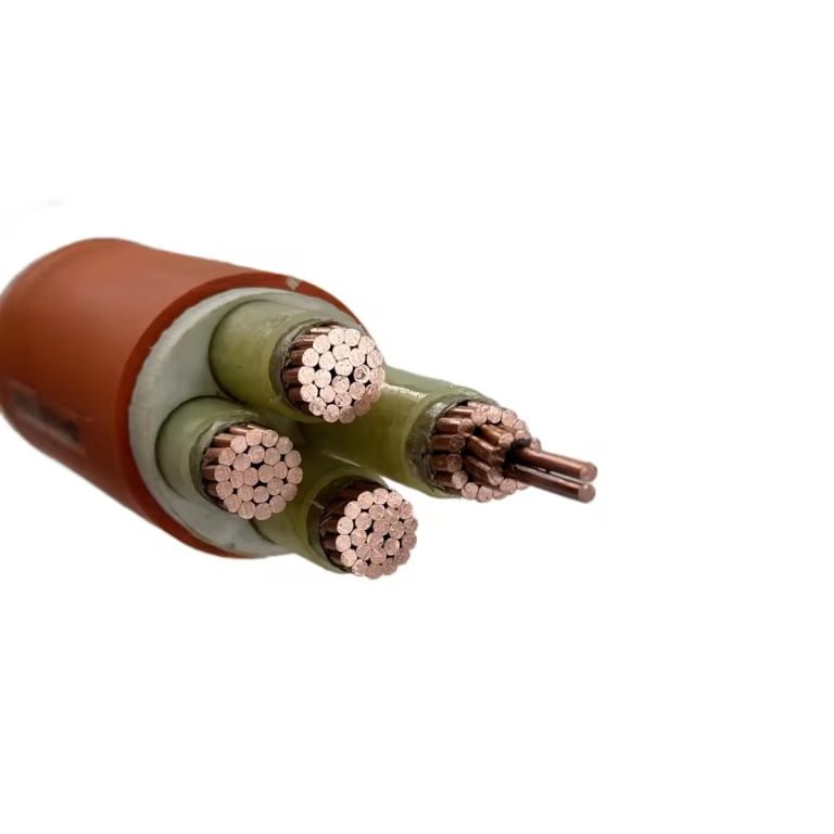
Running low-voltage signal cables alongside mains wiring without thinking it through is one of those shortcuts that looks fine during install and costs you later — sometimes much later. An HVAC control system starts dropping commands intermittently, a security camera feed develops rolling noise, a building automation loop throws false faults nobody can trace. The maintenance team chases sensors, replaces controllers, and burns days before someone finally pulls the tray cover and notices the 14 AWG thermostat wire has been lying against a 12 AWG 120V circuit for thirty feet. By that point you’ve got warranty disputes, callback labor, and possibly a code violation to sort out with the AHJ.
Yes, you can run low-voltage wire next to electrical wire in many situations, but the rules depend on voltage class, separation distance, shielding, and whether both cables share a raceway. NEC Article 725 governs Class 2 and Class 3 circuits and sets specific separation requirements from power conductors. Unshielded low-voltage cables running parallel to mains wiring for more than a meter or two can pick up induced noise, and in some configurations the arrangement is a code violation regardless of whether interference actually occurs.
What makes this genuinely tricky is that “low voltage” covers an enormous range of applications — a 12V doorbell circuit behaves nothing like a 0–10V analog dimming signal or a twisted-pair data run in a controls panel — and the consequences of getting separation wrong scale with what that signal is actually doing. A noisy doorbell is an annoyance. A noisy 4–20 mA loop driving a combustion air damper is a different category of problem entirely. The answer, as it turns out, is less about whether you can and more about understanding exactly when you can’t.
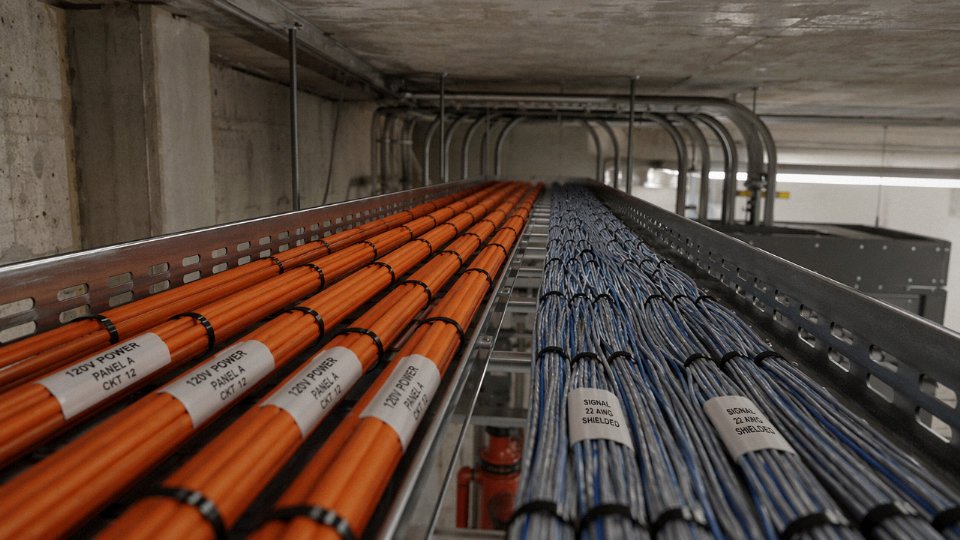
The Physics Behind Interference: How Power Cables Degrade Low-Voltage Signal Integrity
Most electricians know they’re supposed to keep low-voltage signal cables away from power wiring. Fewer can explain exactly why — and that gap matters, because once you understand the mechanism, you stop guessing at separation distances and start making defensible engineering decisions.
Capacitive Coupling: The Electric Field Problem
Every unshielded power conductor running at 120V or 240V AC carries an alternating electric field that extends outward into surrounding space. When a low-voltage cable sits within that field, the two conductors act as the plates of an unintentional capacitor, with the cable insulation and air gap serving as the dielectric. The AC voltage difference drives displacement current across that gap — a current that doesn’t require any physical contact. The induced voltage scales roughly with parallel run length and drops off as you increase separation distance, so a 3-meter parallel run at 25 mm spacing creates meaningfully worse interference than the same run at 150 mm. For unshielded cables carrying 12–50V DC signals, even a few millivolts of injected noise can corrupt a 4–20 mA instrumentation loop or trigger false readings on a building automation sensor.
Inductive Coupling: Faraday’s Law on the Plant Floor
The magnetic field problem is separate and, in many industrial environments, worse. Alternating current through a power conductor generates a time-varying magnetic flux. Any nearby conductor loop — your low-voltage cable and its return path forming a closed area — will have a voltage induced into it according to Faraday’s law:
V_induced = −N · dΦ/dt
For a practical rough estimate at 50 Hz: a 1-meter parallel run between an unshielded 230V power cable and a small-loop signal cable at roughly 50 mm separation can induce somewhere in the range of 5–30 mV, depending on the loop area enclosed by the signal circuit, the current magnitude in the power conductor, and whether anything ferrous is nearby acting as a flux concentrator. That range widens considerably on the factory floor where power cables carry 10–100A loads. For a thermocouple or RTD input rated in microvolts per degree, 20 mV of induced hum is catastrophic.
Conducted Interference and Ground Loops
Physical separation alone doesn’t solve everything. Conducted interference travels through shared grounding infrastructure. Two pieces of equipment bonded to the same ground bus but at different physical locations will often sit at slightly different ground potentials — sometimes 50–200 mV apart — due to resistive voltage drop along the ground conductor from other loads. That potential difference drives a circulating current through any low-voltage signal cable connecting them, injecting 50/60 Hz hum directly into audio, data, or instrumentation circuits. This is the ground loop problem, and it bites hardest in older plants where grounding was designed for safety rather than signal integrity.
VFDs and Harmonics: The Modern Complication
The fundamental 50/60 Hz coupling problem was manageable in plants running across-the-line motors. Variable-frequency drives changed that. A VFD’s switching output generates harmonics well into the kilohertz range — typically up to 2–10 kHz and sometimes higher depending on the carrier frequency setting — and its common-mode noise can radiate aggressively from motor cables acting as unintentional antennas. This broadband EMI is far more difficult to filter out at the receiving end than a clean 50 Hz sine wave. In practice, any instrumentation cable within 300–400 mm of an unshielded VFD output cable is at real risk, and I’ve seen plants where temperature readings on a process line were dancing ±5°C purely from radiated drive noise.
IEC 60364-4-44 specifies minimum separation distances between power and signal cables based on installation conditions, including 50 mm minimum in open air and 200 mm in worst-case EMI environments without shielding.True
IEC 60364-4-44 Table 44A classifies installation conditions and assigns required separation distances: 25 mm with a metal partition between cables, 50 mm minimum in open air, and up to 200 mm in environments with significant electromagnetic disturbance and no shielding measures in place.
Where Shielded Cable Changes the Equation
A foil or braided shield around a low-voltage cable intercepts the displacement current from capacitive coupling and diverts it to ground rather than letting it enter the signal conductor. It also attenuates inductive coupling, though its effectiveness there depends heavily on whether the shield is grounded at one end only (correct for most instrumentation, to avoid creating a ground loop through the shield itself) or both ends. Steel wire armoring adds a ferromagnetic layer that partially attenuates low-frequency magnetic fields — useful near transformers or large motor feeders. The practical result: a properly shielded, single-point-grounded instrumentation cable can often run at 50 mm from a power circuit where an unshielded equivalent would need 200 mm or more, and in some conduit-separated installations the separation requirement effectively drops to near zero. The shield doesn’t make the physics go away; it just redirects the energy somewhere harmless.
Code and Standard Requirements: NEC, IEC 60364, and EN 50174 Rules You Must Follow
Knowing the physics is one thing. Having the exact code language ready when a contractor argues with you on-site — or when an AHJ shows up for inspection — is another matter entirely.
NEC Article 725: The Three-Class Framework
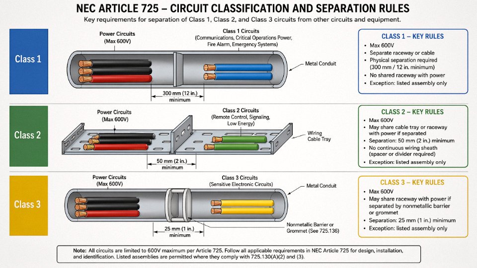
NEC Article 725 is where most North American low-voltage separation disputes start. It divides remote-control, signaling, and power-limited circuits into Class 1, Class 2, and Class 3, and the separation requirements are not interchangeable between them.
Class 1 circuits operate at up to 600V and carry enough energy that they’re treated almost identically to power wiring — they can share a raceway with power conductors under specific conditions, provided conductors are insulated for the highest voltage present.
Class 2 and Class 3 are the ones most installers deal with: thermostats, security sensors, audiovisual signal runs, building automation. These may not occupy the same cable tray, conduit, junction box, or enclosure as line-voltage power conductors unless one of three narrow exceptions applies: a listed assembly that is inherently limited in its power source, a physical barrier fixed within the enclosure and listed for that purpose, or a factory-assembled multi-conductor cable specifically listed for the mixed installation. In practice, those exceptions almost never apply in field-installed systems. Assume separation is required until proven otherwise.
NEC Articles 800 and 820: Communications and Coaxial
Article 800 (communications wiring — voice, data, structured cabling) and Article 820 (coaxial cable for broadband and CATV) are even more restrictive. Both prohibit co-routing with electric light or power conductors in the same raceway, period — the exception carve-outs in Article 725 don’t carry over. For open wiring situations where cables run without conduit, the working minimum is 50 mm of physical separation from power conductors. Smaller gaps are technically permissible only with a fixed, non-conductive separator — and many AHJs reject that interpretation anyway.
NEC Article 800 prohibits communications cables from sharing a raceway with electric light or power conductorsTrue
NEC 800.133(A)(2) explicitly prohibits communications wires and cables from being installed in any raceway, compartment, outlet box, junction box, or similar fitting containing conductors of electric light or power circuits.
IEC 60364-4-44: Installation Categories and Separation Distances
IEC 60364-4-44 approaches the problem differently, using installation categories A through D defined by how circuits are routed relative to each other. Category A is the most relaxed — cables in separate conduits with an earthed metallic screen between them. Category D is bare cables in open air with no intentional separation. The required separation distances scale accordingly, ranging from essentially zero for fully screened cables in separate grounded conduits up to 200 mm or more for unshielded cables routed openly alongside power conductors. Shielding and earthing continuity both factor into which category you can claim — a shield that isn’t properly terminated at both ends gives you almost nothing in terms of EMC benefit.
EN 50174-2: Structured Cabling Specifics
EN 50174-2 is the standard most IT and building cabling installers should have memorized but usually don’t. Its separation table is the clearest in any standard I’ve encountered:
| Power cable type | Minimum separation from unshielded data cable |
|---|---|
| Unshielded power cable | 200 mm |
| Shielded power cable | 100 mm |
| Power cable in metallic conduit | 50 mm |
| Data cable in metallic conduit | Separation significantly reduced |
These figures assume unshielded data cable on the receiving end. Run shielded data cable — properly earthed screened twisted pair, not just foil-wrapped and left floating — and you can often halve those distances, though you should confirm with the cable manufacturer’s own installation data.
Industrial Environments: VFDs Change Everything
In process plant environments, IEC 61918 (industrial communication networks) and IEC 61000-5-7 (EMC installation and mitigation guidelines) both address cable segregation explicitly because the interference sources are far more aggressive than in a commercial building. Variable frequency drives generate high-frequency harmonics that ordinary 50/60 Hz separation rules don’t adequately address. A 750 kW VFD motor feeder running parallel to a PROFIBUS segment or a 4–20 mA process signal loop for even a few meters can corrupt data or introduce enough noise to cause nuisance trips. The practical guidance in IEC 61918 is to treat VFD feeders as a separate segregation class from standard power conductors — minimum 300 mm separation from unshielded signal cables, and ideally routed on physically separate cable trays on opposite sides of a cable tray bridge or racking system.
Jurisdiction Variations: Verify Before You Specify
BS 7671 (the UK’s IEE Wiring Regulations, 18th Edition) and AS/NZS 3000 (the Australian/New Zealand Wiring Rules) both adopt the IEC 60364 framework but with local amendments that can shift specific separation distances or add requirements for particular installation types. The authority having jurisdiction always has final say, and code editions matter — an inspector working from a 2018 edition may cite requirements that were modified in 2023. Before specifying cable routing on any cross-border or export project, verify which edition is currently adopted in that jurisdiction. Don’t assume the version you know from your home market applies everywhere.
Accepted Co-Routing Methods: When and How Running Both Cable Types Together Is Legally Permitted
The codes are not a blanket prohibition. They are a conditional permission with specific engineering requirements attached. Once you understand the four recognized strategies, co-routing becomes a design decision rather than a gamble.
Physical Separation by Distance
IEC 60364-4-44 organizes separation requirements by interference severity category. In practice, the working number most installers use is 50 mm minimum parallel separation between unshielded low-voltage signal cables and unshielded power conductors in a common tray or open wiring run — but that figure assumes low-interference environments. In higher-interference zones (variable-frequency drives, large motor feeders, fluorescent ballast circuits), the standard pushes separation to 100–200 mm depending on cable type and run length.
The detail that trips up even experienced electricians: the 90-degree crossing rule. When a low-voltage cable crosses a power cable perpendicularly, IEC 60364-4-44 requires only 25 mm clearance at the cross point — not the full parallel separation distance. Measure the parallel run length, not the total cable length. A signal cable that shares 0.3 m of parallel proximity before diverging doesn’t trigger the same requirements as one that runs 15 m alongside a 240V feeder. If your parallel run exceeds roughly 1–2 m, separation distance alone becomes increasingly unreliable without shielding, especially at 50/60 Hz where inductive coupling noise can reach 5–50 mV in unshielded conductors at close spacing.
Grounded Metallic Divider in a Shared Cable Tray
NEC Article 725 and IEC 60364-4-44 both recognize a grounded metallic partition within a shared cable tray as functionally equivalent to full spatial separation. This is the practical solution in dense industrial installations where tray real estate is limited — you split a single wide tray with a steel or aluminum divider rather than running two separate trays.
The grounding continuity requirement is non-negotiable. The divider must be bonded to the tray’s grounding conductor at every section joint, which means using listed tray divider hardware with integral bonding straps rather than field-cut angle iron bolted loosely into position. Inspection checkpoint: measure continuity end-to-end on a long tray run before closing up the installation. A resistance above a few ohms across the divider length indicates a broken bond somewhere and the shielding effect is compromised. Wiremold, Legrand, and similar manufacturers produce listed divider kits specifically for this application; improvised dividers don’t carry a listing and will fail inspection in most jurisdictions.
Individual Metallic Conduit per Circuit Type
Running each circuit type in its own EMT or rigid steel conduit provides shielding at the conduit wall itself. Under this configuration both conduits can occupy the same cable tray, wall chase, or underground duct bank with no additional spacing requirement under most code interpretations — the conduit IS the separation. This is the cleanest method from a future-maintenance standpoint because the physical containment is obvious to anyone working on the installation years later.
EMT is acceptable for most commercial applications. In wet or corrosive environments, rigid steel or PVC-coated rigid conduit is the right choice. The conduit fill calculations still apply independently for each circuit type.
Listed Composite and Hybrid Cable Assemblies
Some cable manufacturers produce UL-listed assemblies that combine a shielded Class 2 circuit and a power conductor within a single outer jacket, specifically designed and tested for co-routing. These carry explicit listing language on the nameplate — look for “CL2” or “CL3” markings alongside the power conductor rating. If the nameplate doesn’t explicitly list the composite assembly for co-routing, the listing doesn’t cover that application regardless of what the sales sheet says.
A standard shielded Cat6 cable run in the same conduit as a 120V circuit is code-compliant without additional measures.False
NEC Article 725.136 and 725.143 require separation or specific listed assemblies; general-purpose data cables are not listed for co-routing with power conductors unless the conduit provides full metallic shielding and the installation meets all other applicable conditions.
Routing Hierarchy for Complex Facilities
In petrochemical plants, data centers, and large smart buildings, the standard practice is tiered tray segregation: dedicated trays for high-voltage power, low-voltage power, control and instrumentation, and data/communications — each physically separated or vertically stacked with power trays at top, signal trays at bottom. This isn’t just a code strategy; it reflects operational reality. Mixed routing creates diagnostic nightmares when a noise problem surfaces eighteen months after commissioning.
Label every cable at each tray access point, junction box, and penetration. NEC 725.143 specifically requires identification of Class 2 and Class 3 conductors. Future maintenance workers shouldn’t have to guess what’s in a tray to know whether adding a new cable violates the separation rules already in place.
Cable Construction Features That Enable or Prevent Safe Co-Routing
The code sections tell you what’s permitted. The cable datasheet tells you whether your actual product qualifies. These are two separate conversations, and conflating them is where procurement errors happen — usually discovered during inspection, occasionally discovered during a fault.
Insulation Voltage Rating: It’s About the Tray, Not the Signal
A 24V DC control cable sounds like it only needs minimal insulation. In practice, if that cable shares a tray or conduit with 600V power conductors, NEC 725.136 requires the low-voltage cable’s insulation to be rated for the highest voltage present in the installation — 600V in this case. This catches a lot of people off guard when they’re spec’ing instrumentation cables from a catalog sorted by signal type rather than installation voltage.
The practical implication: always check the column labeled “rated voltage” or “Uo/U” on the datasheet, not the “operating voltage” or “signal range.” A cable marked 300/500V is not compliant in that mixed tray. You need 0.6/1kV insulation. This is a BOM-level decision, not a field judgment call.
Shielding Types and What Transfer Impedance Actually Means
Shielding is where the performance numbers start mattering. Aluminum-polyester (Al/PET) foil gives you 85–100% optical coverage and costs almost nothing to add in manufacturing, but the foil tears easily during installation and the drain wire contact can loosen over time — especially in applications with repeated flexing. Fine for a static instrument run in a cable tray. Not ideal anywhere the cable moves or where maintenance crews are pulling and re-routing cables regularly.
Tinned copper braid at 85–95% optical coverage costs more and adds weight, but its transfer impedance stays low across a wider frequency range, which is why it’s the default recommendation in VFD-heavy environments. A 480V VFD produces switching noise well into the kilohertz range; foil shielding’s performance degrades sharply above a few hundred hertz, while braid holds up considerably better. In plants with multiple variable-frequency drives — common in HVAC, water treatment, and food processing — specifying braid shielding on any analog signal cable co-routed near drive output conductors is just standard practice.
Combination shields (foil plus braid) give you the best of both: high coverage, low transfer impedance, and reasonable flex life. Attenuation for a well-constructed combination shield typically runs 40–60 dB across the 50 Hz–1 MHz band, depending on braid coverage and drain wire termination quality.
Aluminum-foil shielded cables provide adequate EMI protection in VFD-heavy environmentsFalse
Foil shielding degrades significantly at frequencies above a few hundred hertz. VFD switching noise extends into the kilohertz range, where braid or combination shields are substantially more effective.
Armor: Mechanical Protection and Low-Frequency Magnetic Shielding
Steel wire armored (SWA) and steel tape armored (STA) cables serve double duty — physical protection in direct burial or exposed runs, plus meaningful attenuation of low-frequency magnetic fields from 50/60 Hz power conductors. The ferromagnetic steel intercepts flux that a shield alone won’t stop.
For higher-frequency interference, aluminum wire armored (AWA) is actually the better choice. Steel’s higher resistivity limits eddy-current formation, which is exactly what you want for low-frequency work. Aluminum’s lower resistivity means stronger eddy currents and better attenuation above roughly 1 kHz. In mixed industrial environments with both power-frequency and switching-frequency noise sources, specifying AWA and braid shielding together covers most realistic interference scenarios.
Jacket Materials: Not Just Chemical Resistance
LSZH (Low Smoke Zero Halogen) jackets are mandatory in enclosed public spaces, tunnels, and transportation infrastructure under IEC 60332-3 and most transit authority specs. In open industrial cable trays — outdoor substations, open plant floors — standard PVC jackets remain acceptable and substantially cheaper.
XLPE insulation deserves a mention here because it’s often overlooked in the co-routing context. Where control cables run near heat sources — steam lines, furnace conduit, heat-traced piping — XLPE’s thermal rating (typically 90°C continuous versus 70°C for PVC) directly affects whether the cable maintains its insulation resistance over time. Degraded insulation resistance in a shared raceway is a slow fault: the cable continues working until suddenly it doesn’t, and tracing intermittent ground faults in a mixed raceway is miserable.
Relevant Product Lines for Co-Routing Scenarios
Shielded multi-core control cables in the KVV and KVVP series cover the majority of industrial control co-routing requirements. The KVVP designation indicates an added copper tape or braid shield — specifying the braid coverage percentage when ordering matters more than most procurement teams realize. For instrumentation runs near high-interference sources, armored and individually-shielded pair cables provide per-pair isolation that prevents cross-talk between channels, not just interference from external power cables.
Fire-resistant versions meeting IEC 60332-1 (single vertical cable flame test) and IEC 60332-3 (bundled cable tray flame propagation) are the appropriate specification wherever cables pass through fire compartments or where continued circuit integrity during a fire event is required — a growing requirement in industrial and commercial projects globally.
Reading a Datasheet for Co-Routing Compliance
Four fields determine compliance: rated voltage (confirm it covers the highest voltage present in the installation), shielding coverage percentage and type (foil, braid, or combination), armor designation (SWA/STA/AWA and the material), and the listed standards (NEC listing, IEC 60332 series, EN 50174 where applicable). If any of these fields are missing or vague on the datasheet, that’s the first question to send back to the manufacturer before the purchase order goes out. Substituting a compliant cable post-installation is expensive. Catching it at the BOM stage costs nothing.
Real-World Application Scenarios: Industrial Plants, Smart Buildings, and Residential Installations
The code requirements are one thing. What actually happens on a job site — inside a stud bay at 4 PM on a Friday, or on a cable ladder 8 meters above a process floor — is something else entirely. Each environment has its own failure modes, and the fix that works in a smart home wall cavity is not the fix you reach for on a 690V motor feeder run.
Residential Smart Home Installations
This is where the most common violations happen, and they’re almost always driven by convenience rather than ignorance. A low-voltage installer pulls doorbell wire, a thermostat cable, and a Cat6 data run through the same stud bay where the electrician already stapled NM-B (Romex) 14/2 to the stud face. Looks tidy. Gets inspected and passed by an inspector who didn’t look closely at the low-voltage bundle.
The problem: NEC 800.133 prohibits communications cables (including Cat6) from occupying the same enclosure — which courts and inspectors have applied to stud bays acting as enclosed pathways — as conductors of electric light or power circuits. NEC 725.136 reinforces this for Class 2 and Class 3 circuits, requiring separation or a barrier where both circuit types share the same physical space. Inside a stud bay, “physical separation” in practice means at minimum 50 mm of air gap, no crossing contact, and absolutely no bundling with the same staple or cable tie. In practice, the cleanest residential solution is a dedicated low-voltage raceway — even a simple open-slot wire mold stapled to the opposite stud face keeps everything compliant and makes future troubleshooting faster. Bundling doorbell wire and Romex together with a zip tie is not a judgment call; it’s a code violation.
Commercial Office Building Structured Cabling
Cable tray management in a commercial building gets complicated fast. A typical scenario: Cat6A horizontal runs and multimode fiber sharing a 300 mm wide ladder tray with 120V and 277V lighting branch circuits. EN 50174-2 provides a separation distance table based on cable type and whether shielding is present. For unshielded twisted pair (UTP) running parallel to unshielded power cables, the required separation is roughly 200 mm along the full parallel run. Switch to shielded twisted pair (STP) and that drops to around 50 mm — a meaningful difference when tray real estate is tight.
The financial consequence of getting this wrong is not abstract. EMI-induced network dropouts in a busy office building can run anywhere from a few hours of IT troubleshooting to prolonged intermittent faults that take weeks to trace back to a cabling problem. Downtime costs in a commercial environment — lost productivity, IT labor, possible SLA penalties — typically run $500–$5,000 per incident depending on the size of the operation and how quickly the root cause gets identified. Specifying STP Cat6A from the start, with proper drain wire grounding at one end, costs maybe 15–25% more on the cable line item. That math is easy.
Switching from UTP to STP Cat6A can reduce the required EN 50174-2 separation distance from 200 mm to 50 mm in mixed cable trays.True
EN 50174-2 Table 2 specifies reduced segregation distances when shielded data cables are used, because the shield attenuates capacitive and inductive coupling from adjacent power conductors, provided the shield is correctly terminated and grounded.
Industrial Process Plant Installations
This is the scenario where the consequences of poor cable segregation go beyond network slowdowns and into process safety territory. A 690V motor feeder — a variable-frequency drive output is even worse, given the harmonic content — running alongside 4–20 mA instrumentation loops or Profibus fieldbus cables on a shared cable ladder will induce noise voltages of 5–50 mV depending on parallel run length, proximity, and shielding. That sounds small until you remember that the full span of a 4–20 mA loop represents only a 16 mA range. A few millivolts of induced noise translates directly to measurable, erratic process readings. Flow control goes unstable. A temperature loop hunts. Operators start overriding automatic control because they don’t trust the instruments.
IEC 61000-5-7 defines cable segregation classes (Class A through Class E) based on voltage level and signal sensitivity, and a properly designed industrial installation segregates instrumentation cables — regardless of run length — from power cables rated above roughly 50V AC. On a cable ladder, this means physical dividers, separate tray sections, or (the most reliable approach) individually shielded, armored instrumentation cable routed in its own dedicated cable ladder positioned at least 300 mm from the power tray. Armored, individually shielded multi-pair instrumentation cables from a manufacturer with verified IEC compliance essentially carry their own EMI protection, which gives you a degree of tolerance when separation distances can’t be maintained through a congested equipment room.
Common Mistakes Seen Across All Three Environments
A few patterns show up everywhere, regardless of whether the installation is a house or a refinery.
Stapling low-voltage and power cables to the same support point seems harmless — it’s mechanical support, not electrical contact. But it forces the cables into physical contact at the tie point and eliminates any separation benefit over that span. Inspectors catch this less often than they should.
Using the same junction box for both power and low-voltage circuits without a physical barrier violates NEC 725.136 directly and is surprisingly common in retrofit work where a spare knockout was convenient.
Omitting drain wire grounding on shielded cables is probably the single most expensive mistake in structured cabling. A shield with both ends floating, or worse, one end grounded to a painted enclosure surface, provides almost no EMI rejection. The shield has to terminate to a clean ground at one end (both ends in some industrial environments using differential techniques), and the drain wire has to make solid metal-to-metal contact.
What a Compliant Mixed Cable Tray Installation Actually Looks Like
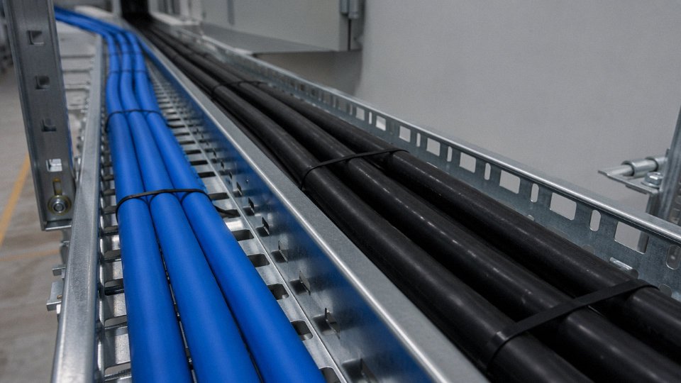
Picture a 600 mm wide cable ladder with a full-length aluminum divider down the center. One side carries 277V lighting branch circuit conductors in orange conduit sleeves, clearly labeled every 1.5 meters. The other side carries STP Cat6A in blue, fiber in yellow, and 4–20 mA instrument pairs in individually shielded overall-armored cable in gray — each type resting in its own color-coded section, with cable ties to the ladder rung, not to each other. Grounding jumpers bond tray sections every 3 meters. The drain wires on every shielded instrument cable terminate to a grounded bare copper bus strip running the length of the tray. It looks almost excessive until you’ve spent two days troubleshooting an intermittent process fault that turned out to be a single ungrounded shield.
That’s the mental model worth holding onto — separation is not bureaucratic caution; it’s the physical implementation of the interference physics described earlier in this article.
Specification and Procurement Guide: Selecting the Right Cable for Mixed-Routing Environments
Getting the physics and the code right means nothing if the cable you actually receive on-site doesn’t match what the specification required. Procurement errors here tend to surface at the worst possible moment — during commissioning, when a control loop is oscillating and someone finally checks the cable drum label and finds unshielded instrumentation cable installed in a VFD-dense panel room. The following steps translate everything covered earlier into a concrete purchasing and specification workflow.
Step 1 — Classify the Installation Environment First
Before writing a single line-item on the bill of materials, determine the IEC 60364-4-44 EMC environment category for the route in question. A lightly loaded residential or small commercial environment (Environment 1) has modest interference levels and generally allows unshielded Class 2 wiring with adequate physical separation — typically 50 mm or more for runs under a few meters. Medium-density commercial (Environment 2) requires more care, particularly in buildings with variable-speed HVAC, LED drivers, or UPS systems. Heavy industrial with VFDs, arc furnaces, or large motor starters falls into the highest threat category and changes nearly every downstream decision. Getting this classification wrong early means buying cable that either fails in service or, in the other direction, over-specifying and paying 30–60% more per meter than the application actually needs.
Step 2 — Inventory What’s Already in the Shared Route
Walk the route before specifying. Document the voltage level, the continuous current, whether the power conductors are unshielded THHN in open tray or SWA-armored cable, and — critically — whether the source is a clean utility feed or a harmonic-rich VFD output. A 480V drive output at 60 Hz fundamental with substantial 5th and 7th harmonic content is a fundamentally different threat than a lightly loaded 120V circuit feeding a lighting panel. Unshielded power cable in open tray is the worst-case scenario for adjacent signal cables. If you can’t get that information from the electrical engineer of record, measure: a clamp meter with harmonic analysis capability on an existing similar circuit in the facility will tell you quickly.
Step 3 — Match Low-Voltage Cable Shielding to the Threat Level
Unshielded low-voltage cable is not recommended in any environment where the parallel run exceeds roughly 1–2 meters alongside power conductors — and in industrial environments, it shouldn’t be used in shared raceways at all, regardless of run length. Foil-shielded cable (aluminum-polyester) is adequate for light commercial environments where the power side is clean and currents are moderate, provided the shield is terminated at one end to a solid ground reference, not floating. In heavy industrial environments with VFDs, specify braid-shielded cable — 85% coverage minimum — or consider SWA/STA armored instrumentation cable where mechanical protection and shielding are both required. Drain wire gauge matters too; undersized drain wire on a foil shield creates ground loops that can make interference worse, not better.
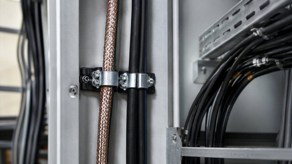
Step 4 — Verify the Insulation Voltage Rating, Not Just the Operating Voltage
A 24V DC signal cable operating comfortably at a fraction of its design voltage still needs insulation rated for the worst-case exposure in the tray. If that cable shares a conduit or open tray with 600V conductors, most applicable codes require the insulation to be rated at 300V or 600V minimum. Specify this explicitly on the purchase order. Manufacturers sometimes ship instrumentation cable rated at 150V or 250V by default; in a 600V-class tray, that’s a code violation regardless of operating voltage.
Step 5 — Confirm Standards Compliance Before the Reel Leaves the Factory
Check drum labels for IEC 60227 or IEC 60245 (for flexible low-voltage cables), IEC 60502 (power cables), and IEC 60189 (instrumentation and data cables). For industrial control cable, EN 50525 is increasingly referenced in European projects. Ask for third-party test reports — not just a manufacturer’s own certificate — and verify ISO 9001 certification is current.
IEC 60502 covers power cables with rated voltages from 1 kV up to 30 kV, and is not the correct standard for low-voltage signal or instrumentation cables.True
IEC 60502-1 applies to extruded solid dielectric insulated power cables rated 1 kV to 3 kV. Instrumentation and signal cables in mixed-routing environments are governed separately by IEC 60189 and related standards. Specifying the wrong standard on a BOM creates confusion at the factory and risks receiving an incorrect product.
Supply Chain Considerations for International Projects
Armored and braid-shielded specialty cables are not catalog items that ship from stock in most international projects. Lead times from Chinese manufacturers typically run 4–10 weeks for standard shielded types and 8–16 weeks for custom constructions, depending on copper availability and reel length requirements. Minimum order quantities for specialty instrumentation cable tend to fall in the range of 500–2,000 meters per SKU, though this varies by manufacturer and project volume. For bulk procurement, working directly with a manufacturer rather than a trading house avoids one layer of specification translation — critical when the insulation voltage rating, shield coverage percentage, and drum-length tolerance all need to match a specific project requirement. Jinda’s production capacity across five bases — totaling 470,000 m² — and in-house R&D capability mean that non-standard constructions, such as paired foil-and-braid shielded multicore cables or custom armored instrumentation cables, can be engineered and sampled without routing through a third party. Available certifications include CCC, CE marking, and IEC compliance, with UL-listed products available for projects requiring North American code compliance. Ask for certification documentation specific to the cable construction you’re ordering, not a general company certificate that may not cover the exact product on your BOM.
Frequently Asked Questions About Running Low-Voltage Wire Next to Electrical Wire
Can I run a doorbell wire (16V AC) in the same conduit as a 120V circuit?
No. NEC Article 725 is unambiguous on this: Class 2 circuits cannot share a raceway with power conductors unless the Class 2 cable is rated for the higher voltage present and the assembly is listed for that combined use. Standard doorbell wire — typically 18 AWG, rated 30V or less — does not meet that insulation requirement. Putting it in the same conduit as a 120V run is a code violation, full stop.
In practice, the fix is simple and cheap. Run a separate ½-inch conduit for the doorbell circuit, or maintain a minimum 50 mm open-air separation for exposed runs. A lot of residential electricians skip this because doorbell circuits feel inconsequential. They’re not — insulation failure on that thin wire inside a shared conduit can energize the doorbell transformer secondary and create a genuine shock hazard at the push-button.
Is it safe to run Cat6 network cable alongside power cables in a wall?
It depends — on the distance, the shielding, and how long the parallel run actually is. Unshielded Cat6 (UTP) needs at least 200 mm of parallel separation from 120V power wiring under EN 50174-2. That’s roughly 8 inches, which is more than most stud bays provide if cables are just stapled wherever convenient.
Shielded Cat6 — STP or SFTP with proper drain wire continuity and grounded terminations — reduces that requirement to around 50 mm. Crossing the power cable at 90 degrees is permitted with minimal clearance, which is why installers who know the rules always try to cross, never run parallel. The 90-degree crossing geometry collapses the inductive coupling to nearly zero.
Shielded Cat6 (STP/SFTP) reduces minimum parallel separation from power cables to approximately 50 mm under EN 50174-2, compared to 200 mm for unshielded UTP.True
EN 50174-2 Table 6 specifies separation distances based on cable shielding category and local EMI environment; shielded cables are permitted reduced clearances because the shield intercepts the coupled electric field before it reaches the signal conductors.
What happens if my security camera cable touches a 240V power cable?
At minimum, you’re risking slow insulation degradation — heat and dielectric stress at the contact point that won’t show up immediately but will fail in a year or two, usually at the worst possible time. More acutely, insulation failure at 240V can inject voltage spikes directly into the camera’s signal circuitry, destroying the input stage. In the event of a hard fault, you’re looking at a shock hazard on the cable sheath or a fire if the fault current finds a path to combustibles.
Any section where physical contact has occurred should be replaced and re-routed — not just inspected and left alone. Insulation that has been mechanically stressed at a contact point is compromised even if it measures fine with a basic continuity check.
Do shielded cables eliminate the need for separation entirely?
No. Shielding handles capacitive coupling well and cuts inductive coupling significantly, but it doesn’t zero it out — especially at 50/60 Hz where the wavelengths are long and even a modest shield transfer impedance allows some coupling through. IEC 60364-4-44 still requires 25–50 mm minimum separation for shielded cables in moderate EMI environments. The closest you get to eliminating the requirement is armored cable pulled through a continuous metallic conduit, which creates a Faraday-cage effect around the low-voltage circuit. Even then, most plant-floor engineers I’ve worked with keep at least 25 mm as a maintenance margin — cables shift over time, conduit fittings loosen, and that buffer matters.
Can low-voltage landscape lighting wire run next to underground power cables?
Underground runs fall under NEC 300.5 and IEC 60364-5-52, and the separation requirements are more demanding than above-grade work, not less. Direct-buried low-voltage cable should be at least 300 mm from power cables — measured vertically or horizontally depending on the trench configuration. Separate conduits are the cleaner solution and make future fault-finding far less painful. Always confirm with the local utility, too; some municipalities impose additional clearance requirements beyond the base code, particularly near service entrance conductors.
How do I know if my cable is rated for co-routing with higher-voltage conductors?
Start with the nameplate printed on the cable jacket. You’re looking for the insulation voltage rating — 300/500V and 600/1000V are the common IEC designations; UL-listed cables will show a voltage rating in the product name (e.g., THHN/THWN-2, rated 600V). For co-routing to be legitimate, the low-voltage cable’s insulation rating must meet or exceed the highest voltage present in the shared space.
Beyond voltage rating, check the shielding coverage percentage (85% braid coverage is a common minimum for industrial signal cables; 95%+ is better), confirm the drain wire is properly specified, and verify the listing mark — UL, CE, or the relevant national mark for your jurisdiction. A reputable cable manufacturer will provide a full technical data sheet with all of these parameters. If a supplier can’t produce that document on request, that’s your answer about whether to buy from them.
Summary Checklist and Final Engineering Recommendations for Compliant Low-Voltage and Power Cable Co-Routing
Everything covered in this article distills to a sequence of decisions you have to make before the first cable tie goes on. Skip steps, and you’ll be cutting open finished walls or pulling conduit out of cable trays six months after commissioning. The checklist below is not exhaustive for every jurisdiction, but it covers the failure points that actually cause rework.
10-Point Compliance Checklist
1. Classify the environment. Residential, light commercial, industrial, and heavy industrial environments each carry different EMC exposure levels under IEC 60364-4-44 and EN 50174-2. Get this wrong and every downstream decision about separation and shielding is based on the wrong baseline.
2. Measure the actual separation distance available. Don’t assume the drawings are accurate — walk the route. In practice, ceiling plenum space and cable tray fill often force cables closer than the design intent. Document the minimum achievable gap.
3. Select the segregation method before ordering. Separate conduits, divided cable trays with metallic barriers, or dedicated cable ladders — choose the method that fits the physical space and then verify it against the applicable code edition. Switching methods mid-project is expensive.
4. Verify insulation voltage rating. Low-voltage cables in a mixed-routing environment should carry an insulation rating with margin above the highest voltage present. A 300/500V-rated cable sitting 30 mm from a 240V circuit in an industrial environment is not the same risk as one rated 600/1000V.
5. Confirm shielding type and verify ground continuity. Foil shields, braided shields, and combination constructions each perform differently across frequency ranges. A shield is only as good as its termination — a floating shield on a long parallel run can make noise worse, not better.
6. Label everything, both ends. Unlabeled low-voltage cables get spliced into power circuits during maintenance. It happens more often than it should. Color coding alone is not labeling.
7. Identify the code edition in force for the project. NEC editions are not adopted uniformly across U.S. states; IEC adoptions vary by country. Confirm with the AHJ before finalizing the specification, not after.
8. Get AHJ approval on the co-routing method before installation. Some inspectors will accept a divided cable tray; others will require separate conduits regardless of what the code technically permits. Find out early.
9. Test before closing up. For data cables, run NEXT (near-end crosstalk) testing per TIA-568 or ISO/IEC 11801 as applicable. For power cables, perform insulation resistance testing at appropriate voltage. These tests catch installation damage that visual inspection misses entirely.
10. Update as-built drawings. The as-built is what the next engineer uses when something fails at 2 a.m. on a Sunday. If it’s wrong, the troubleshooting time doubles.
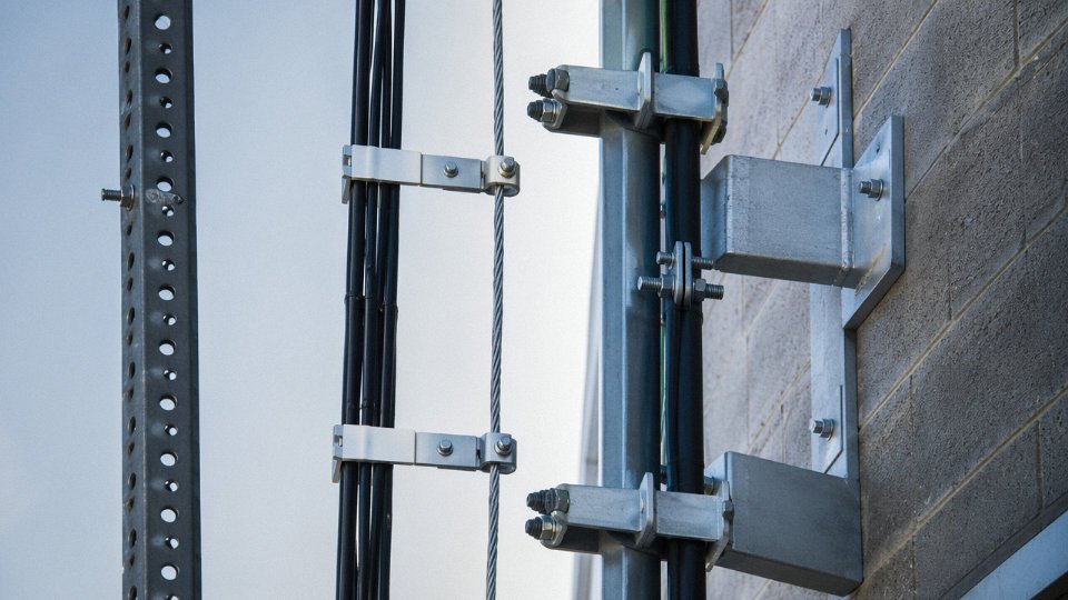
Tiered Cable Selection Logic
Start with the separation distance the code requires for your EMC environment classification. Then select shielding that reduces the required separation to what the physical space can actually deliver. After that — not before — verify insulation voltage rating. Finally, confirm that the construction meets the applicable standards referenced in your project specification. Running this sequence in order prevents two common and opposite mistakes: over-specifying an expensive shielded, armored cable for a residential thermostat run, or under-specifying an unshielded cable for a variable-frequency drive environment where induced noise will trip process interlocks.
The Real Cost of Getting It Wrong
EMI-induced process downtime in a manufacturing plant typically runs $10,000–$100,000 per hour, depending on the process and whether a buffer stock exists upstream. Insurance claims tied to wiring fires from improper cable co-routing routinely exceed $500,000, and that figure doesn’t include production loss or reputational exposure. Correct specification at the design stage — the right cable, the right routing method, the right separation — costs a fraction of what remediation costs after commissioning. In my experience, the projects that skip this step usually do so to save a few hundred dollars on cable or a few hours on design time.
A floating, ungrounded shield on a long parallel cable run can increase induced noise rather than reduce it.True
An ungrounded shield can act as an antenna, coupling additional noise into the conductor rather than providing a return path for induced currents. Proper single-point or both-ends grounding, depending on the application, is required for the shield to function as intended.
Why the Manufacturer Matters at Scale
Specification compliance is only as reliable as the cable that actually arrives on site. A vertically integrated manufacturer with in-house quality control and third-party certified test facilities — Jinda has operated that model since 1987, supplying projects across 50+ countries — can produce consistent insulation ratings, shield coverage percentages, and conductor geometry across large order quantities. That consistency matters when you’re pulling cable across a 200,000 m² facility and the 500th reel needs to perform identically to the first. Sourcing from a manufacturer that can provide traceable test data for each production batch also simplifies AHJ approval and insurance documentation.
Jinda’s technical support team can advise on project-specific cable selection, co-routing configurations, and custom constructions for unusual EMC environments. If you’re in the specification or procurement stage, request technical data sheets and sample cables for evaluation before committing to a bill of materials — it’s a straightforward step that eliminates a significant category of risk.