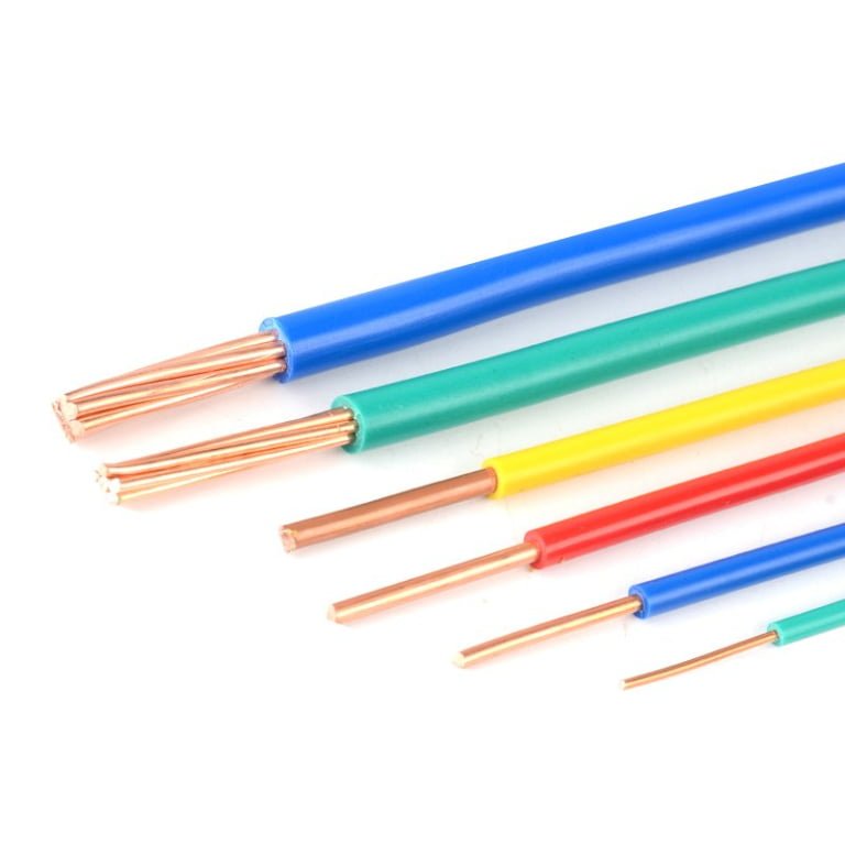
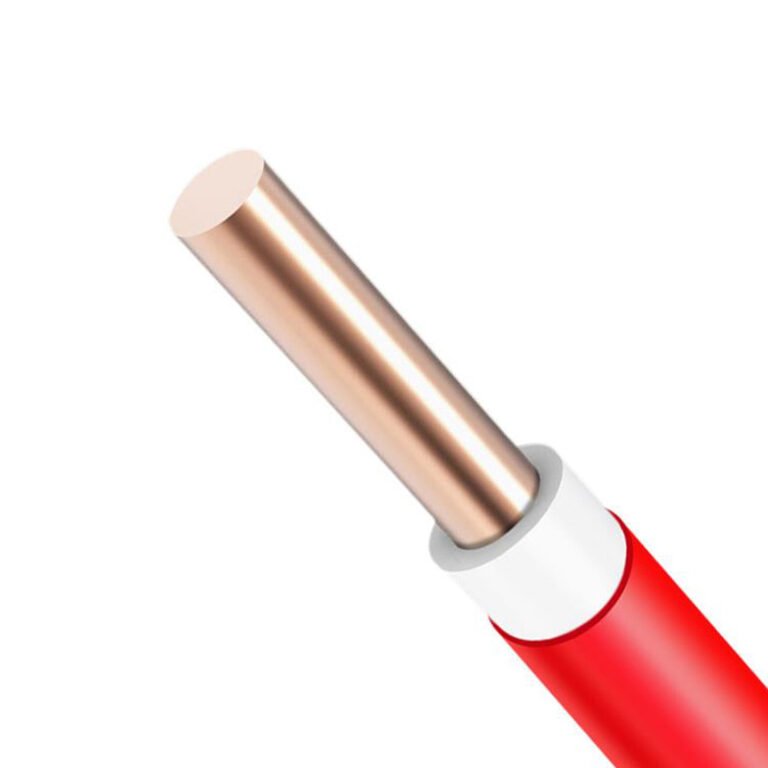
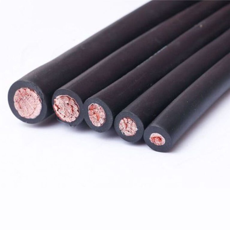
Specify “low voltage wire” on a purchase order without understanding what actually separates it from general-purpose wiring, and you will eventually pay for that gap — either in a failed inspection when the insulation grade doesn’t match the installation environment, in premature insulation breakdown that takes a production line down mid-shift, or in a procurement audit that flags mismatched ratings as a liability. The confusion is understandable: walk into most electrical supply houses and the physical difference between a “regular” wire and a low voltage wire looks trivial. It usually isn’t.
Yes, there is a real difference. Low voltage wire is formally defined by IEC 60038 as wire rated for systems at or below 1,000 V AC or 1,500 V DC, and it is engineered to that boundary — with insulation thickness typically between 0.6 mm and 2.0 mm depending on conductor cross-section and voltage class, conductor geometry optimized for known current and resistivity targets, and jacket materials selected for the specific mechanical and thermal stresses of low voltage distribution. “Regular wire” has no single standard definition, which is exactly where specification errors begin.
What makes this worth digging into is that the differences are layered — some are obvious once you know where to look, others only surface when something goes wrong. The gap between the two categories touches conductor material selection, insulation engineering, regulatory compliance, and total installed cost in ways that aren’t always obvious from a datasheet. Understanding the full picture changes how you spec, how you procure, and how you troubleshoot.
How Voltage Classification Systems Define ‘Low Voltage’ Across IEC, NEC, and Global Standards
The phrase “low voltage wire” gets used loosely on procurement documents, project specs, and distributor catalogs — sometimes meaning anything below 1,000 V, sometimes meaning 12 V landscape lighting cable, sometimes meaning whatever the writer happened to be looking at. That inconsistency creates real problems when a factory owner in Southeast Asia is sourcing cable for a project that needs to satisfy both a European equipment supplier and a local electrical inspector working off a different code. Getting the classification right before you write the purchase order saves a lot of rework.
IEC 60038: The International Baseline
IEC 60038 is the standard most international cable manufacturers — and the datasheets they produce — use as their reference. It divides the voltage landscape into three bands that directly determine how a cable is engineered:
Extra-Low Voltage (ELV): up to 50 V AC or 120 V DC. At these levels, the primary insulation design concern shifts away from dielectric breakdown and toward mechanical protection and environmental exposure. Think automotive wiring, 24 V DC control loops, and Class 2 instrumentation circuits. Wall thickness can be minimal from a voltage standpoint, but the jacket still needs to handle abrasion, oil, or UV depending on where it sits in the plant.
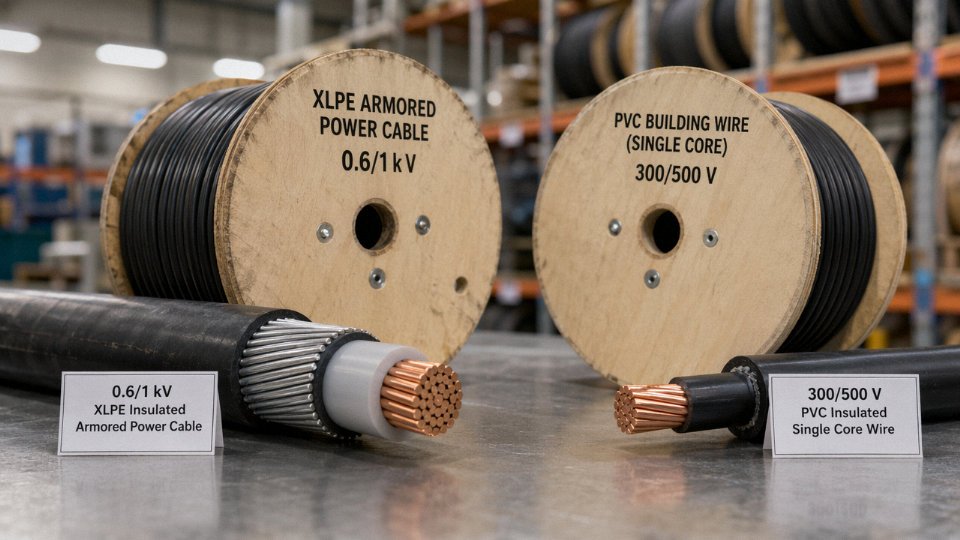
Low Voltage (LV): 50 V to 1,000 V AC, or up to 1,500 V DC. This is the band that covers the overwhelming majority of industrial and commercial electrical infrastructure — motors, lighting panels, distribution boards, building circuits. Insulation thickness in this range typically runs from around 0.6 mm on small cross-sections at 300/500 V rated cables up to roughly 2.0 mm on larger conductors in the 600/1,000 V class, depending on conductor size and the specific voltage designation. Standard cable types here include PVC-insulated building wire, NYY power cable, and XLPE-insulated armored cable.
Medium Voltage (MV): 1 kV to 35 kV. Cable design changes substantially — you now need semiconductive screening layers, carefully controlled conductor stranding, and often metallic shielding to manage electric field stress. Procurement and installation errors that are merely inconvenient at LV become genuinely dangerous at MV.
NEC and the North American Parallel System
The NEC (NFPA 70) doesn’t organize its world the same way. Rather than drawing a single threshold at 1,000 V, it introduces circuit classifications — Class 1, Class 2, and Class 3 remote-control and signaling circuits — that are defined by power output limits and use conditions, not purely voltage. A Class 2 circuit, for instance, caps at 30 V and 100 VA, which influences cable sizing, overcurrent protection requirements, and permitted wiring methods independently of what IEC would say about the same voltage level. When you’re sourcing cable for a machine that ships to North America but was designed to IEC specs, this parallel system is where the confusion usually starts. The voltage might fall well within what both systems call “low,” but the permitted cable types and installation methods can diverge.
IEC 60038 defines Low Voltage as systems operating at or below 1,000 V AC or 1,500 V DC.True
This threshold is the internationally recognized definition under IEC 60038, used as the basis for cable ratings, switchgear design, and safety standards across most global markets.
BS 7671 and AS/NZS 3000: Export Market Nuances
The UK’s BS 7671 (18th Edition) broadly aligns with IEC voltage bands but uses its own cable designation conventions — H07V-R, H05VV-F, and similar harmonized codes — that don’t always appear on non-European cable drums. Australia and New Zealand follow AS/NZS 3000, which references its own approved cable standards under AS/NZS 5000. Both markets will scrutinize whether your cable carries the right voltage designation and third-party mark, not just whether the underlying engineering is equivalent. For export projects, assume the inspector will check the drum print, not just the test report.
Reading the U₀/U Notation
Every cable drum or reel from a reputable manufacturer should show a rated voltage in the format U₀/U — for example, 0.6/1 kV or 300/500 V. U₀ is the rated voltage between any conductor and earth (or the metallic screen); U is the rated voltage between any two phase conductors. A cable marked 0.6/1 kV is designed for systems where the conductor-to-earth voltage doesn’t exceed 600 V and phase-to-phase doesn’t exceed 1,000 V. That’s your low voltage cable in IEC terms. When buyers see “regular wire” on a local supplier’s price list, it almost always refers to 300/500 V or 450/750 V single-core PVC building wire — which sits squarely inside the LV band. It isn’t a separate category. It’s a specific, relatively modest subset of it.
| Standard | ELV Upper Limit | LV Range | Typical Cable Types in LV Band |
|---|---|---|---|
| IEC 60038 | 50 V AC / 120 V DC | 50 V–1,000 V AC / 1,500 V DC | NYY, XLPE armored, PVC single-core (H07V-R) |
| NEC (NFPA 70) | ~30 V (Class 2 circuit) | Up to ~600 V (most distribution) | THHN/THWN, NM-B, MC cable |
| BS 7671 | 50 V AC | Up to 1,000 V AC | H07V-R, SWA armored, FP200 |
| AS/NZS 3000 | 50 V AC | Up to 1,000 V AC | V-90, X-90, SDI cable (AS/NZS 5000 series) |
The practical takeaway: before specifying “low voltage wire,” state which standard governs the installation. The voltage band may overlap across IEC, NEC, and BS 7671, but the cable type designations, test requirements, and permitted installation methods do not.
Insulation Material and Thickness Engineering: The Core Technical Difference Between Wire Types
The gap between wire types isn’t a marketing category. It’s physics. Insulation has to do two things: hold off voltage without breaking down, and survive the thermal and mechanical environment it lives in for 20–40 years. Get either wrong and you’re looking at insulation failure, ground faults, or a fire — not someday, but eventually and predictably.
Dielectric Strength and Why Rated Voltage Sets the Floor
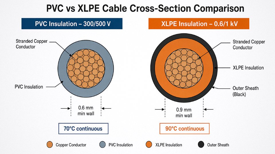
Every insulation system is sized around peak voltage plus a safety margin baked into the standard. A 0.6/1 kV cable — the workhorse of industrial LV distribution — must withstand the AC spark test at 3.5 kV for one minute under IEC 60502-1. A 300/500 V building wire per IEC 60227 is tested at 2 kV. That difference in test voltage drives the minimum insulation wall thickness, which is why you cannot substitute a 300/500 V rated flex for a 0.6/1 kV installation even if the conductor size is identical. The numbers look similar on paper. The safety margins are not.
PVC: The Baseline Material and Its Real Limits
PVC (polyvinyl chloride) dominates standard building wire globally, and for most indoor fixed wiring in conduit, it’s perfectly adequate. It’s cheap, flexible at room temperature, easy to terminate, and bonds well to copper. The standard conductor temperature rating is 70°C continuous — fine for lightly loaded residential and commercial circuits.
Where PVC causes problems: direct UV exposure degrades it within a few years, leaving the insulation brittle and cracked. Anyone who’s stripped old outdoor PVC wire knows the insulation doesn’t peel — it shatters. In cable trays near process equipment with oil mist, solvent splashes, or ozone-generating motors, PVC absorbs plasticizer leaching over time and eventually stiffens. These are installation environment issues, not product defects. Specifying PVC in those conditions is the error.
XLPE: When the Thermal Load Actually Matters
Cross-linked polyethylene (XLPE) starts as ordinary PE, then undergoes a chemical or radiation-induced crosslinking process that creates a three-dimensional polymer network. The result is insulation that won’t soften and flow under sustained heat — typically rated 90°C continuous, 130°C short-circuit peak for many constructions. That roughly 20°C conductor temperature advantage over PVC translates directly to current-carrying capacity: the same 16 mm² copper conductor carries noticeably more amperes in XLPE than PVC, which sometimes lets you drop one conductor size and still meet the load. In a large substation fit-out with hundreds of feeder runs, that cross-section reduction can be meaningful in copper weight.
XLPE is harder to strip cleanly with basic tools and is less forgiving during termination if a jointer scores the insulation wall. It’s worth training the crew before the cable is already in the tray.
LSZH: The Confined-Space Requirement That Keeps Growing
Low Smoke Zero Halogen insulation has moved from a niche specification to a near-standard requirement in tunnels, metro systems, hospitals, ships, and data centers. The reasoning is straightforward: PVC, when it burns, releases hydrogen chloride gas — corrosive, toxic, and dense enough to disorient people trying to evacuate a confined space within seconds. LSZH compounds use mineral-filled polyolefin bases (typically with aluminium trihydrate or magnesium hydroxide as flame retardants) instead of halogenated additives.
Visually, LSZH cable is often slightly stiffer and has a matte, slightly chalky surface texture compared to the glossy finish of standard PVC. It requires different bending radius allowances on installation — ignore this and you stress the insulation at the termination point.
LSZH cables produce significantly less toxic and corrosive smoke than PVC cables in fire conditionsTrue
PVC insulation releases hydrogen chloride (HCl) gas when burned; LSZH compounds are halogen-free and designed to minimize toxic smoke emissions, which is why IEC 60332 and IEC 61034 fire performance standards are routinely specified alongside LSZH cable requirements in public and marine applications.
Insulation Thickness by Conductor Cross-Section
The figures below are nominal wall thicknesses under IEC 60227 (300/500 V, typical building wire) and IEC 60502-1 (0.6/1 kV industrial cable). Actual production tolerances allow a minus allowance per standard — usually around 10–15% of nominal — so don’t expect every reel to measure exactly at nominal.
| Conductor Size | IEC 60227 (300/500 V) | IEC 60502-1 (0.6/1 kV) |
|---|---|---|
| 1.5 mm² | 0.7 mm | 0.8 mm |
| 2.5 mm² | 0.8 mm | 0.8 mm |
| 6 mm² | 1.0 mm | 1.0 mm |
| 16 mm² | 1.0 mm | 1.0 mm |
| 35 mm² | 1.2 mm | 1.2 mm |
| 70 mm² | 1.4 mm | 1.4 mm |
The convergence at larger cross-sections reflects that conductor-to-conductor spacing — not raw voltage withstand — starts to drive insulation geometry once you’re above roughly 10 mm².
Jacket, Sheathing, and Armoring: Not a Voltage Issue
The outer sheath on a multicore cable is not additional dielectric protection. It mechanically binds the cores, resists abrasion, and provides a substrate for printing the cable identification. Steel wire armoring (SWA) or aluminum wire armoring (AWA) adds a layer of crush and impact resistance — critical for direct burial, cable runs through concrete, or anywhere mechanical damage is a realistic hazard. AWA is standard where the cable runs alongside AC systems and magnetic losses in steel armor would otherwise be a concern.
None of this has anything to do with voltage class. A 0.6/1 kV SWA cable and a 0.6/1 kV unarmored cable have identical insulation wall thickness. The armor is an installation environment decision, not a voltage decision. Procurement teams sometimes conflate armored with “higher rated.” They’re different axes entirely.
Conductor Design Differences: Stranding, Cross-Section, and Material Selection Across Wire Categories
The insulation gets most of the attention in specification documents, but the conductor construction is where real application failures tend to originate. Wrong stranding class for a flex application, aluminum where the termination hardware expects copper, undersized cross-section because someone applied a residential ampacity table to an industrial motor circuit — these are the choices that generate warranty disputes and unplanned downtime.
Solid vs. Stranded Conductors: IEC 60228 Class 1 and Class 2
IEC 60228 defines the conductor classes that matter most in everyday specification work. Class 1 is solid — one conductor, no stranding. It’s practical and economical for fixed building wiring up to about 16 mm², where the cable won’t flex after installation and terminations into screw clamps or DIN rail devices are clean and repeatable. Above 16 mm², solid conductors become stiff enough that installation crews struggle to route them through conduit bends without kinking, which is why stranded Class 2 conductors take over for larger fixed installations. Class 2 gives you the same DC resistance as an equivalent solid conductor but breaks the conductor into multiple wires — typically 7 to 19 strands depending on cross-section — making the cable manageable in tight cable trays.
The distinction matters for procurement because Class 1 wire looks identical in cross-section to Class 2 on a datasheet if you’re not checking the conductor construction column. In a switchgear assembly plant, substituting Class 2 where Class 1 was specified (or vice versa) can cause connection problems with ferrule-type terminals designed around one specific geometry.
Fine-Wire Stranding: Class 5 and Class 6 for Flexible Service
Class 5 and Class 6 are where the stranding count jumps significantly — dozens to hundreds of fine wires, depending on the cross-section. This construction is used in flexible cords, portable tools, trailing cables, and anywhere the cable bends repeatedly during service life. The physics is straightforward: more, finer wires distribute bending stress across a larger number of individual elements, and no single wire carries enough of the load to fatigue-crack quickly. A 2.5 mm² Class 5 conductor might use 50 wires of 0.26 mm diameter; the same cross-section in Class 2 uses 7 wires of about 0.68 mm. Flex life difference is substantial — typically an order of magnitude or more in repeated-bend testing, though actual service life depends heavily on bend radius, cycle rate, and temperature.
One practical catch: fine-wire conductors measure slightly higher resistance than their nominal class would suggest if the individual wires aren’t perfectly parallel (they aren’t — they spiral). This is normal and accounted for in the IEC standards, but it occasionally causes confusion when a technician measures resistance on a reel and finds a value a few percent above what a solid-conductor table predicts.
Copper vs. Aluminum in Low Voltage Systems
Copper’s resistivity runs around 1.72 × 10⁻⁸ Ω·m at 20°C; aluminum sits at roughly 2.82 × 10⁻⁸ Ω·m. That’s a conductivity gap of about 60%, which forces a cross-section upsize when substituting aluminum for copper. The standard rule of thumb is two IEC cross-section steps — so where 16 mm² copper is specified, you’re looking at 25 mm² aluminum, give or take depending on installation conditions and the specific ampacity table you’re working from.
Aluminum’s real advantage is weight and cost per meter, which matters enormously on long distribution runs — utility feeders, large industrial buildings, overhead service entrances. A 240 mm² aluminum cable weighs roughly 35–40% less than the equivalent copper cable, and on a 500-meter pull that’s a meaningful difference for installation labor and cable tray loading calculations.
The termination question is where aluminum causes the most trouble in practice. Aluminum forms an oxide layer almost immediately on a freshly cut surface, and aluminum oxide is a decent electrical insulator. Jointing aluminum conductors without proper preparation — meaning a no-ox compound, correct torque sequence on compression lugs, and hardware rated specifically for aluminum — leads to high-resistance connections that heat up under load, eventually failing. Many industrial facilities have a blanket policy of copper-only for anything below 35 mm² specifically to avoid this problem at the termination level, even when the cable run itself would work fine in aluminum.
Conductor Surface Treatments
Bare copper is the default for most building and industrial wiring — it’s cheaper and makes excellent contact with standard terminal hardware. Tinned copper adds a thin layer of tin (typically 1–5 µm, though this varies by specification) that dramatically slows the surface oxidation that can increase contact resistance over time in humid environments. Marine cables, food-processing facilities that wash down with hot water and chemicals, outdoor junction boxes in coastal regions — these are the applications where you’ll find tinned conductors specified almost universally. Tinning also improves solderability, which still matters in certain control panel and instrumentation applications where soldered connections are preferred over crimp.
One thing worth knowing: tinned conductors can complicate certain gas-tight crimp connections because the tin layer affects the cold-weld mechanism. It’s not a problem when you’re using hardware designed for tinned conductors, but mixing tinned wire into a connector system spec’d for bare copper is worth flagging to whoever is selecting the terminal hardware.
Cross-Section Sizing Logic for Industrial Low Voltage Systems
Four separate requirements actually drive the conductor cross-section decision, and “regular wire” sizing tables typically only address one or two of them.
Ampacity — continuous current-carrying capacity — is the obvious one and the one most sizing guides lead with. But voltage drop over distance is often the binding constraint on long runs. A motor fed from a distribution panel 150 meters away on a modestly sized cable can see terminal voltage drop under heavy load that causes the motor to draw higher current to maintain torque, which heats the cable further. It’s a self-reinforcing problem.
Short-circuit withstand is the third constraint. The conductor has to survive the thermal energy of a fault until the protective device clears it. This is calculated from the fault current, the clearing time of the upstream breaker or fuse, and the conductor’s adiabatic heat capacity — and for large cables close to the source, it can produce a minimum cross-section that’s larger than what ampacity alone would suggest.
Motor starting current is the fourth, and it catches people out regularly. Induction motors on direct-on-line starting draw 5–8 times full-load current for several seconds. Sizing the feeder cable purely on running ampacity and ignoring the starting event usually still works thermally (the event is brief), but the voltage drop during starting can be severe enough to affect other equipment on the same bus — and that effect gets worse as the feeder cable gets longer or undersized.
Production Scale and Conductor Consistency
Consistent conductor quality across a large international order depends heavily on manufacturing infrastructure. Conductor diameter uniformity, strand lay length, and surface treatment consistency are all process variables that drift when production is fragmented across multiple small operations. Jinda’s five production bases and 470,000 m² of integrated manufacturing space provide the process control and batch-to-batch consistency that matters when a procurement manager is sourcing 50,000 meters of cable for a single project and can’t afford to find out in the field that reel 200 behaves differently from reel 20.
Aluminum conductors require a minimum two cross-section step increase over equivalent copper conductors for the same ampacity in standard low voltage cable applications.True
This follows from the resistivity difference between copper (≈1.72 × 10⁻⁸ Ω·m) and aluminum (≈2.82 × 10⁻⁸ Ω·m), and is consistent with IEC 60364 and most national low voltage wiring standards that publish parallel copper/aluminum ampacity tables.
Application Environments That Demand Low Voltage Cable Over Standard Wiring
Understanding the physics and standards is one thing. Knowing where that distinction actually costs you money — or gets someone hurt — is what matters on the job.
Residential and Commercial Building Wiring
Standard 300/500 V or 450/750 V rated wire is entirely appropriate for internal fixed wiring installed inside conduit, trunking, or wall cavities where it’s protected from mechanical damage and moisture. That’s what it was designed for. The trouble starts when someone grabs the same reel and runs it as a direct-burial garden supply, or pulls it through an exposed outdoor tray in a rooftop plant room. Neither application is appropriate. Direct burial demands a cable with moisture-resistant sheathing — typically PVC or PE outer jacket rated for the purpose — and in many jurisdictions a specific burial voltage class. A standard NYM-J or similar 300/500 V cable dropped into a ground trench without armoring will absorb moisture at the cut ends within a season or two, leading to insulation resistance failures that are notoriously difficult to trace.
Industrial Power Distribution Panels and Motor Feeders
This is where under-specification causes real downtime. Motor control centers (MCCs), switchgear feeders, and variable frequency drive (VFD) output cables are almost universally specified at 0.6/1 kV. The reason isn’t just continuous voltage — it’s transient overvoltages. VFDs generate voltage spikes that can reach 2× the DC bus voltage at the motor terminals, particularly on longer cable runs. A 450/750 V building wire used as a VFD output cable may survive commissioning and fail six months later during a load surge, taking the motor winding with it. Replacing a burnt stator is expensive. Tracing the root cause back to undersized cable insulation takes time most plants don’t have.
VFD output cables should be rated 0.6/1 kV minimum to withstand reflected wave overvoltages in inverter-driven motor circuits.True
Reflected wave phenomena in PWM-driven VFD circuits can produce peak voltages well above the nominal system voltage, particularly on cable runs over roughly 15–20 meters. IEC and NEMA application guidelines for VFD installations consistently recommend 0.6/1 kV cable ratings for this reason.
Renewable Energy: Solar PV and Wind
Solar DC string voltages routinely reach 1,000 V DC on utility-scale arrays, and some 1,500 V DC systems are now common. Standard building wire is not rated for DC at these levels, and it’s certainly not rated for continuous UV exposure. Solar cable standards — TÜV EN 50618 and IEC 62930 for marine/offshore PV — specify UV stabilization, ozone resistance, and temperature cycling performance that a generic PVC insulated wire simply cannot match. Skipping the proper solar cable to save a few cents per meter is the kind of decision that voids system warranties and creates ground-fault conditions that are genuinely dangerous to service personnel.
Underground Direct Burial
Beyond voltage class, buried cables need armoring — steel wire armor (SWA) or aluminum wire armor (AWA) — plus a moisture-resistant outer sheath. The armor protects against rodents, settling soil, and incidental excavation damage. Standard surface-mount wire has neither. In wet climates, an unarmored cable buried without a gel-filled or MDPE sheath will typically show insulation degradation within three to five years, depending on soil chemistry and water table depth.
Marine and Offshore Installations
Standard building wire is outright prohibited here. IEC 60092 governs marine cable construction: halogen-free, low smoke, resistant to oil, salt spray, and vibration. LSZH (low smoke zero halogen) sheathing is mandatory on passenger vessels and most offshore platforms because toxic smoke in an enclosed hull during a fire is the worst-case scenario. A procurement team that substitutes a standard XLPE/PVC cable to cut costs on a vessel fit-out is creating a flag-state inspection failure and a liability exposure.
Data Centers and Critical Infrastructure
European CPR (Construction Products Regulation) cable classes — Eca through Cca — determine how cable flame performance is verified and documented for building certification. IEC 60332 flame test categories govern this in international projects. Specifying the wrong class doesn’t just fail an inspection; it affects building insurance ratings and, in the event of a fire, creates legal exposure for the specifying engineer. In critical infrastructure, the cable class is a design decision, not a procurement afterthought.
Export Project Alignment
When cables ship across borders, voltage class and insulation type must match the destination country’s wiring regulations, not the exporter’s home standard. A 450/750 V cable acceptable under one national code may be non-compliant under another jurisdiction’s distribution rules. Working with a manufacturer experienced in multi-country supply — one that can produce 0.6/1 kV, 300/500 V, or specialized variants to IEC, BS, or AS/NZS standards from the same facility — eliminates the re-specification risk that otherwise surfaces at project commissioning, usually at the worst possible time.
International Standards Certification Landscape: CE, UL, CCC, and What Marks Actually Guarantee
Certification marks on cable jackets look authoritative. Some are. Some are printed there because a sales rep knew they would reassure a procurement manager who wouldn’t check. Knowing what each mark actually obligates a manufacturer to do — and how to verify it — is probably the most underused skill in international cable procurement.
IEC 60227 and IEC 60502-1: The Foundational Standards
IEC 60227 covers PVC-insulated cables rated up to 450/750 V and is the baseline standard most plant electricians are actually working with when they specify general low voltage wiring. It mandates conductor construction (minimum strand counts, conductor resistance per cross-section), insulation compound properties and minimum thickness by voltage class, marking requirements, and a defined battery of electrical and mechanical tests — including spark testing at the line, bending, and insulation resistance after immersion. IEC 60502-1 steps up to power cables rated 1 kV through 3 kV and adds requirements for extruded insulation screening, sheath integrity under more aggressive conditions, and stricter conductor resistance tolerances. A cable claiming IEC 60502-1 compliance but lacking documented test results for the voltage-withstand and partial-discharge tests is a flag worth chasing before you sign a purchase order.
CE Marking: Legal Weight, Not Third-Party Verification
CE is widely misread as a quality mark. It isn’t. Under the Low Voltage Directive 2014/35/EU and the Construction Products Regulation (which governs cables in fixed installations), the CE mark is the manufacturer’s own declaration that the product conforms to applicable EU directives. No external body stamps that mark on — the manufacturer does. What this means practically: a legitimate CE declaration carries legal liability back to the manufacturer or EU-based importer, which is real leverage. But there’s no inspection event behind it the way there is behind a UL listing. Ask for the Declaration of Conformity document, the specific directive references, and the technical file summary. If a supplier hesitates on any of those, that’s informative.
UL Listing: Continuous Factory Testing Is the Actual Value
For North American projects, the relevant standards are UL 44 (thermoset-insulated wire and cable), UL 83 (thermoplastic-insulated wire and cable), and UL 1277 for electrical power and control tray cable. UL-listed means UL has conducted initial product testing and maintains a follow-up inspection program at the factory — typically quarterly unannounced visits with production samples pulled and tested. “Recognized” (the UR mark) is a component-level designation for parts that go into end products; it does not authorize direct use in final installations the way a full Listing does. Procurement teams sourcing cable for US or Canadian installations should confirm “Listed,” not just “Recognized,” and verify the specific file number on ul.com.
CCC / 3C: Non-Negotiable for China-Destined Product
China Compulsory Certification is mandatory for cable types listed in the CCC catalogue — this includes most PVC-insulated power cables for end-use in Chinese infrastructure. If you’re sourcing from a Chinese manufacturer for domestic Chinese projects, verify the 3C certificate covers the exact product type and cross-section range you’re ordering, not just a superficially similar product line. Jinda holds CCC certification across its relevant product categories, which is verifiable through the CNCA (Certification and Accreditation Administration of China) database.
Regional Certifications Worth Knowing
| Certification Body | Region | Relevant Standard(s) |
|---|---|---|
| BASEC (BSI) | United Kingdom | BS 6004, BS 6346, BS EN 50525 series |
| VDE | Germany | DIN VDE 0276, aligned with IEC 60502 |
| KEMA-KEUR / KIWA | Netherlands | NEN and IEC-aligned cable standards |
| SAA / RCM | Australia / New Zealand | AS/NZS 5000 series |
| SASO | Saudi Arabia | SASO and IEC 60502-based requirements |
Verification in Practice: How to Catch a Fake Mark
Certificate logos are trivially copied. The only reliable check is pulling the certificate number from the cable’s documentation and querying it directly on the issuing body’s public database — ul.com for UL, the CNCA portal for CCC, VDE’s certificate search for VDE marks. A legitimate supplier will hand you that certificate number without being asked twice. Mismatched dates, certificate numbers that return no results, or certificates that cover a different product family than what you’re actually buying are all common patterns with non-compliant product.
Shandong Jinda Special Cable Group holds verifiable international certifications across its low voltage cable product lines, including CCC certification for China-market products.True
As a manufacturer operating since 1987 with documented export to 50+ countries, Jinda maintains compulsory and voluntary certifications as a baseline for international supply. Buyers should request specific certificate numbers and verify independently through issuing body databases, which Jinda's sales team supports as standard practice.
One practical habit worth building into your procurement process: before a container ships, request a copy of the production batch test report alongside the certificate. Standards like IEC 60502-1 require routine tests on every production length — conductor resistance, voltage test, insulation resistance. If a supplier can’t produce those per-batch, the certificate on file doesn’t tell you much about what actually got wound onto that drum.
Cost Structure Analysis: Why Low Voltage Cables Are Priced Differently From Standard Wire
If you’ve ever sat across from a supplier offering a 20% discount on “equivalent” cable and felt uneasy, that instinct is usually right. The price gap between a properly rated low voltage cable and standard building wire isn’t padding — it reflects real differences in material inputs, processing complexity, and compliance overhead. Understanding what’s actually inside that price lets procurement teams push back on specification downgrades with something more than gut feel.
Raw Material Cost Dominance: Copper and the LME Effect
Copper typically accounts for 60–75% of the total manufactured cost of a standard low voltage cable, depending on conductor cross-section and whether the design is single-core or multi-core. That proportion shifts somewhat for aluminum-conductor designs — aluminum’s higher resistivity (roughly 2.82 × 10⁻⁸ Ω·m versus copper’s 1.72 × 10⁻⁸ Ω·m) means larger cross-sections are needed for equivalent current capacity, so raw material weight per meter goes up even as unit metal cost comes down.
The practical consequence: cable pricing tracks LME copper spot prices with a lag of roughly two to six weeks, depending on a manufacturer’s hedging position and inventory cycle. International procurement orders placed when copper sits above $9,500/tonne will land at meaningfully different unit costs than orders placed during a trough. For large projects — think 50+ tonne cable packages — timing a blanket purchase order against LME trends can shift total material spend by 8–12%, sometimes more. Locking in pricing through a framework agreement with a manufacturer who carries sufficient stock buffer is one of the more underrated procurement levers available.
Insulation Compound Costs: PVC, XLPE, and LSZH Are Not Interchangeable
Standard PVC insulation is cheap and well-understood. XLPE (cross-linked polyethylene) costs roughly 15–30% more per kilogram of compound than equivalent-grade PVC, and that premium is justified by its higher permissible operating temperature (typically 90°C continuous versus 70°C for PVC), better dielectric performance, and longer service life in thermally stressed installations. LSZH (low smoke zero halogen) compounds run 30–60% above comparable PVC, sometimes higher for flame-retardant grades. Specifying LSZH in an open office fit-out because it appeared on a generic spec sheet is a cost mistake; specifying it in a tunnel, a crowded data center cable tray, or a passenger rail application is entirely justified by the toxicity and smoke density reduction it provides in a fire event.
Certification and Testing: A Real Cost, Not a Markup Fiction
IEC, UL, and CE certification involves initial type-testing fees, periodic surveillance audits, and re-testing whenever a compound lot or conductor supplier changes. Spread across production volume, this adds a modest but real per-meter overhead — more significant for lower-volume specialty cables, less so for high-run commodity sizes. A cable priced suspiciously below certified equivalents is frequently uncertified or self-declared. That distinction matters enormously when an insurance claim or a safety investigation traces back to the cable specification.
Certification costs are a genuine quality overhead distributed across production volume, not arbitrary manufacturer markup.True
Third-party testing under IEC 60332, IEC 60228, or UL 44, for example, involves real laboratory fees and annual surveillance costs. These are verifiable through audit records and test certificates. Manufacturers cutting price below market often do so partly by reducing or falsifying certification activity.
Armoring Adds Weight, Processing Steps, and Measurable Cost
Steel wire armoring (SWA) on a 4-core 16 mm² cable adds roughly 0.8–1.4 kg per meter of cable weight and increases per-meter cost by approximately 15–25% over an unarmored equivalent — the range depends on steel wire diameter, lay configuration, and current steel pricing. Aluminum wire armoring (AWA) is lighter and preferred where magnetic losses are a concern (single-core cables especially), but AWA compound cost is less stable and fabrication tolerances are tighter. Neither armoring type is free overhead; both are legitimate cost drivers for applications in direct burial, mechanical exposure, or where rodent activity is a known site condition.
Manufacturing Complexity in Multi-Core Designs
A simple single-core building wire — strand, insulate, spool — is a short production sequence. A screened 4-core low voltage instrumentation cable with individually shielded pairs, a collective foil screen, drain wire, and LSZH outer jacket runs through six to nine production passes with 100% spark testing at the insulation stage and dimensional checks at each. Tighter conductor stranding tolerances for flexible cable (Class 5 or 6 per IEC 60228) also mean slower draw speeds and more die changes. That complexity is reflected in price and is also why delivery lead times vary so much across cable types.
The Installed Cost Perspective Procurement Teams Routinely Miss
Cable material typically represents 8–15% of total electrical installation cost on a commercial or industrial project — the rest being conduit, terminations, labor, testing, and commissioning. Downgrading from a specified XLPE-insulated armored cable to a cheaper PVC unarmored substitute to save 10% on that 8–15% slice saves perhaps 1–1.5% of overall project cost. If that substitution causes a premature failure requiring cable replacement inside a poured slab or a congested cable tray, remediation labor alone can exceed the original cable material cost several times over. Procurement decisions that optimize cable unit price in isolation consistently underperform against decisions that optimize for total installed and lifecycle cost.
Manufacturers operating at scale — multiple production lines, high annual copper throughput, established compound supply agreements — can offer substantially better unit pricing on large international orders without compromising on certified quality. The economics of volume purchasing and stable raw material procurement genuinely do flow to the buyer when the supplier has the manufacturing infrastructure to absorb them.
Common Specification and Installation Mistakes When Distinguishing Wire Types on Real Projects
These errors show up repeatedly across industrial fit-outs, commercial builds, and export projects. Some are careless; more often they come from engineers who genuinely don’t know the boundary between wire categories, because nobody told them and the ampacity table didn’t either.
Using 300/500 V Rated Cable in 0.6/1 kV Distribution Circuits
This is probably the single most consequential substitution mistake on real sites. A 300/500 V rated wire looks identical to a 0.6/1 kV cable from the outside — same color, same conductor cross-section, often the same reel. The insulation wall on the 300/500 V product is thinner by design, and it was never tested to the dielectric stress that a 0.6/1 kV distribution circuit will apply over time. Under continuous voltage stress, the insulation ages exponentially faster. You don’t get an immediate fault; you get progressive degradation over 18–36 months until the insulation can no longer hold, usually in a junction box or tight conduit bend where heat concentrates. Electrical fire investigators consistently flag this substitution as one of the leading cable-related ignition causes in installations that bypassed proper inspection. The fix at design stage costs nothing — catching it during a site survey after the ceiling is closed costs considerably more.
Sizing by Ampacity Alone
Ampacity tables are not interchangeable across voltage classes, even when the numbers happen to match. A 2.5 mm² conductor carrying 20 A looks the same whether the cable is rated 300/500 V or 0.6/1 kV. The current-carrying capacity might be identical on paper, but the insulation system — its material grade, thickness, and long-term thermal endurance — is categorically different. Procurement teams who pull a current rating from a generic cable catalogue and order the cheapest product that meets that number are essentially ignoring half the specification.
Ignoring Derating for Installation Conditions
Standard ampacity values assume a specific set of conditions: single cable, open air, 30°C ambient, no solar load. In practice, industrial low voltage cable gets routed in bundles of 12–30 cables through enclosed cable trays, sometimes in plant rooms running 45–55°C year-round. The derating factors for those conditions can reduce usable ampacity by 30–50% depending on grouping and ambient temperature. Using the uncorrected table value in a hot, bundled tray installation and then wondering why cables are running warm six months later is a genuine pattern I’ve seen more than once.
Mixing Certification Zones on Export Projects
A cable carrying CE marking is not automatically acceptable on a UL-listed switchboard destined for a North American facility, and vice versa. The underlying test methods, conductor class definitions, and insulation compound requirements differ. This becomes a problem most often during design review when a project team specifies cable from a local supplier certified to one standard, then ships the equipment to a jurisdiction enforcing a different one. Catching this at the bill-of-materials stage is a one-hour review. Catching it during a third-party commissioning audit is a procurement crisis.
IEC 60228 and ASTM B8 define conductor class requirements differently, meaning a cable meeting one standard's Class 5 flexible conductor requirement does not automatically satisfy the other.True
IEC 60228 and ASTM B8 use different stranding and tensile criteria for equivalent conductor classifications, which affects both flexibility performance and termination compatibility across different national standards.
Underestimating Voltage Drop on Long Industrial Runs
Residential wiring practice is built around short circuits — typically under 30 meters. Industrial low voltage distribution runs of 100–400 meters, occasionally longer, are routine. At those lengths, voltage drop drives conductor sizing well above what the thermal requirement would suggest. A 4 mm² conductor may be thermally adequate for the load current, but a 400-meter run at that cross-section could produce a voltage drop exceeding 5–7% depending on power factor and load profile, which causes motor starting problems and nuisance tripping of sensitive equipment. The voltage drop calculation should happen before the thermal check, not as an afterthought.
Confusing ‘Low Voltage’ With ‘Low Specification’
Some buyers treat 0.6/1 kV cable as the budget tier because the voltage rating sounds modest compared to medium voltage products. It isn’t. A properly manufactured 0.6/1 kV XLPE or PVC cable involves controlled compound formulation, precise insulation wall thickness tolerances, and type-testing to IEC 60502-1 that covers conductor resistance, insulation resistance, voltage withstand, and aging performance. The variation in quality within the low voltage category is actually wider than in medium voltage, because the lower barrier to market entry means more manufacturers participate. Cheap low voltage cable is cheap for a reason — typically thinner insulation walls, recycled compound with inconsistent properties, or conductors slightly under the nominal cross-section. None of that shows on a datasheet.
Improper Termination of Aluminum Low Voltage Cable
Aluminum conductors oxidize quickly when exposed to air, forming Al₂O₃ — a layer with much higher electrical resistance than the base metal. Without anti-oxidant compound applied at termination, and without lugs that are specifically rated for aluminum, the joint resistance climbs over time. A high-resistance termination in a 200 A feeder circuit generates heat proportional to I²R; it doesn’t trip a breaker because the overall circuit current is within rating, but the joint reaches temperatures that carbonize insulation and eventually fail. Correct torque specification matters too — aluminum is softer than copper and creeps under sustained mechanical stress, which loosens connections that were correct at installation. This requires re-torquing on a maintenance schedule, something that rarely makes it into the handover documentation.
Frequently Asked Questions About Low Voltage Wire and Regular Wire Differences
Can I use regular household wire for a low voltage lighting system?
This comes up constantly, and the answer depends on what you mean by “low voltage lighting.” Most landscape lighting, LED drivers, and under-cabinet systems run at 12 V or 24 V DC — properly classified as extra-low voltage (ELV) under IEC 60449. Standard 300/500 V household wire is electrically overspecified for those voltages by a wide margin; the insulation alone could handle far greater stress than the system will ever impose.
The practical problem is form factor and flexibility. Household wire — typically solid or lightly stranded — was designed to be pulled through conduit and stay put. ELV lighting cable is purpose-built with finely stranded conductors (Class 5 or Class 6 per IEC 60228) that tolerate repeated flexing, tight routing around fixtures, and connection to small terminal blocks without work-hardening and cracking over a few seasons. Many electrical codes also require cable rated and marked for the specific application; using unmarked household wire in a signed-off ELV installation creates a compliance gap that will surface during inspection. Use the right product.
What does 0.6/1 kV mean on a cable drum label?
The notation follows IEC 60502 convention: U₀ is the rated voltage between any conductor and earth (or the metallic screen), and U is the rated voltage between any two phase conductors. So 0.6/1 kV means 600 V conductor-to-earth, 1,000 V conductor-to-conductor. This is a low voltage cable — it sits exactly at the IEC 60038 ceiling for LV classification — and it is the workhorse rating for industrial power distribution, commercial building feeders, and motor circuits worldwide. If you see this marking on a drum from any manufacturer, you are looking at a standard LV product, not something exotic.
0.6/1 kV is the most common voltage rating for industrial and commercial low voltage power cable globally.True
IEC 60502-1 specifies 0.6/1 kV as the primary rating class for multicore and single-core power cables used in industrial and commercial LV distribution, and this rating is referenced in national standards derived from IEC across most markets.
Is low voltage wire cheaper than high voltage cable?
Generally yes. Less insulation material, simpler extrusion geometry, no need for semi-conductive screens or high-precision layer bonding — the manufacturing process is genuinely less demanding. That said, “low voltage cable” spans an enormous range. A 1.5 mm² two-core 300/500 V flexible cord costs almost nothing per meter. A 240 mm² armored 0.6/1 kV copper feeder cable with XLPE insulation and LSF sheathing is a significant line item. Cost ultimately tracks conductor cross-section, copper versus aluminum, insulation compound, armor type, and certification. Expecting all low voltage cable to be cheap is how procurement teams end up accepting underspecified product.
Can low voltage cable be buried underground without conduit?
Standard PVC-insulated, PVC-sheathed low voltage cable — the ubiquitous NYY or similar construction — needs conduit or duct for direct burial in most jurisdictions. The sheath provides environmental protection but not the mechanical resistance needed against ground movement, rodents, or incidental excavation. Armored cables — steel wire armored (SWA) or double steel tape armored with a PE outer sheath — are a different matter. Where local regulations permit, properly selected armored LV cable can go directly into a prepared trench, typically with a sand bed and tile warning layer above. Always confirm the specific construction against the project’s local code; “armored” alone is not enough if the outer sheath material isn’t rated for soil contact and moisture exposure in that climate.
How do I verify that a cable from an overseas manufacturer is genuinely certified?
Ask for the full certificate number, the exact issuing certification body name, and the scope of the certificate — which cable constructions and ratings it actually covers. Then check it yourself. UL certificates are searchable on UL Product iQ. VDE marks are verifiable through the VDE database. BSI Kitemark holders appear on the BSI portal. KEMA-KEUR and DNV certificates have their own registries. If the manufacturer hesitates to provide the certificate number, that tells you something. In practice, a few minutes on those databases has caught more than one certificate that listed a different company name or covered a narrower product range than what was being quoted.
Does wire color coding differ between low voltage and regular wire?
Yes, and this is an area where mistakes have real consequences during installation and maintenance. IEC 60446 establishes the base color code — brown/black/grey for phases, blue for neutral, green-yellow for protective earth — but regional variations exist and matter. North American practice follows NEC conventions that differ significantly from IEC. Older European installations may have the pre-harmonization colors. ELV DC systems add polarity identification that three-phase LV systems don’t use. Always specify color coding requirements against the destination country’s current standard, not the manufacturer’s default. A cable shipped from one market into another with mismatched colors will either require re-identification tape throughout — labor cost — or create a live safety hazard during future maintenance.
What is the minimum bend radius for low voltage cable during installation?
Unarmored LV cable: typically 6–8 times the overall cable diameter, depending on conductor class and insulation compound. Armored cable — SWA or STA — runs 12–15 times overall diameter, sometimes higher for larger sizes; the armor wires themselves dictate the limit more than the insulation does. These figures come from IEC 60502 and manufacturer installation guides; your specific cable’s datasheet may be tighter. Violating minimum bend radius isn’t always immediately obvious — the cable doesn’t fail on the day you pull it. Insulation deforms, conductor strands work against each other, and you get premature dielectric degradation or intermittent faults that are genuinely difficult to trace back to the installation bend. On a congested tray or in a tight cabinet entry, it is worth taking the extra ten minutes to route correctly rather than forcing the cable around a corner that’s too sharp.
How to Specify and Source the Right Low Voltage Cable for International Projects With Jinda
Getting the technical knowledge right is only half the job. The other half is translating that knowledge into a cable specification precise enough that a manufacturer can quote accurately — and that a factory owner or project engineer can actually verify on delivery. Vague specs invite substitution. Tight specs protect the project.
Build a Complete Cable Specification Before You Contact Anyone
A fully formed specification for a low voltage cable order should include, at minimum:
- Rated voltage (U₀/U): State this explicitly — 300/500 V, 450/750 V, or 0.6/1 kV are the common LV classes. Don’t just write “low voltage.”
- Conductor material and cross-section: Copper or aluminum, and the cross-sectional area in mm². Also specify whether you need Class 1 (solid), Class 2 (stranded), or Class 5 (flexible) conductors per IEC 60228.
- Number of cores: Single-core, 3-core, 4-core, 5-core — and whether a separate earth conductor is included.
- Insulation and sheathing material: PVC, XLPE, LSZH, EPR — each has a different temperature ceiling and chemical resistance profile, and the difference matters in confined spaces or high-ambient environments.
- Armoring requirement: SWA (steel wire armored), STA (steel tape), or unarmored. Direct burial almost always needs armoring. Cable tray installs often don’t.
- Temperature rating: Typical LV cables are rated −15 °C to +70 °C (PVC) or up to +90 °C (XLPE), but installations near furnaces, compressors, or in tropical climates may push the upper boundary.
- Flame performance class: IEC 60332-1 (single cable), IEC 60332-3 (bunched), or IEC 60754/61034 for LSZH smoke and halogen content.
- Applicable certification standard: IEC, BS, VDE, NFC, AS/NZS — this is driven by the destination country, not the manufacturer’s location.
Miss two or three of these items and you will receive a quote that cannot be fairly compared against alternatives. Worse, you may take delivery of cable that technically meets the partial spec but fails an on-site inspection.
Tell the Manufacturer How the Cable Will Be Installed
Installation method changes the recommended product more than most buyers realize. A 4-core 16 mm² cable laid directly in wet soil in a 45 °C ambient environment in a Gulf-region project needs armoring, a UV-resistant outer sheath, and a temperature-derated current capacity — that is a meaningfully different product from the same conductor size running in a cable tray inside a temperature-controlled European facility. Give the manufacturer the installation method (direct burial, conduit, cable tray, free air), the ambient temperature range, any chemical or mechanical exposure risks, and the destination country’s wiring standard. A competent manufacturer stops guessing and starts specifying the right product.

Why Supplier Breadth Reduces Project Risk
Jinda’s product range runs from 300/500 V flexible cords through 0.6/1 kV multi-core power cables, armored cables, LSZH cables, solar cables (TÜV and IEC 62930 rated), and instrumentation cables. In practice, most mid-to-large projects need several cable types simultaneously — power distribution, control wiring, instrumentation loops, maybe a solar string circuit. Sourcing these from three or four different suppliers multiplies documentation tracking, shipment coordination, and quality audit effort. Consolidating to a single qualified manufacturer with that product breadth is not a convenience argument; it is a project management risk argument.
Jinda supplies customers in more than 50 countries worldwideTrue
This figure is stated in the company's official profile and reflects their established international distribution and project supply history since 1987.
Quality Assurance as Procurement Risk Reduction
Jinda operates an in-house testing laboratory calibrated to IEC standards — conductor resistance, insulation resistance, voltage withstand, flame performance, mechanical tests. For international procurement managers who cannot visit the plant, third-party witnessed testing and factory acceptance testing (FAT) arrangements are standard practice. Five production bases allow parallel production runs on large orders, which matters when a project has a fixed energization date and cannot absorb a four-week queue delay at a single-site supplier.
Lead Times, Logistics, and Documentation
Realistic lead times for standard LV cable from stock or short-run production range from roughly 2 to 6 weeks depending on conductor cross-section, armoring complexity, and order volume — custom constructions or large tonnage orders push toward 8 to 12 weeks, so early engagement with procurement matters. Jinda’s logistics experience across more than 50 countries means the documentation package — packing lists, test reports, certificates of conformity, country-of-origin certificates, and where required, material declarations for REACH or RoHS — arrives complete and in the format customs and project engineers actually need.
Submit your project specification or sample requirements to Jinda’s technical support team. The response is a product recommendation and a quotation, backed by an after-sales and technical support infrastructure built for ongoing supply relationships — not a one-time transaction. For procurement managers building a long-term supply chain, that distinction is worth more than the lowest unit price on a single container.