
Specify the wrong wire and the consequences stack up fast: insulation that can’t handle peak load temperatures starts degrading within months, a control circuit wired with undersized conductors introduces voltage drop that makes a VFD fault intermittently, or an outdoor run rated for dry locations only turns brittle and cracks after one winter. None of those failures announce themselves clearly. They show up as unexplained downtime, nuisance trips, or a smoldering junction box at 2 a.m. Getting the application match right from the start is cheaper than any of those outcomes.
Low voltage wire — rated at or below 1,000 V AC (or 1,500 V DC) per IEC 60228 and NEC standards — is used across building power distribution, lighting circuits, motor and HVAC control wiring, instrumentation, renewable energy systems, EV charging infrastructure, and data/signal runs. Conductor sizes span roughly 0.5 mm² for signal work up to 400 mm² for heavy feeder circuits, with the right choice depending on load current, installation method, ambient temperature, and applicable code.
What makes low voltage wire genuinely interesting from a procurement and engineering standpoint is how much variation hides under one label. A wire called “low voltage” in a solar DC string circuit, a tunnel lighting grid, and a factory motor control panel might share a voltage class on paper but need completely different insulation chemistry, flexibility ratings, and mechanical protection. The global market for this cable category was sitting around USD 40 billion in 2023 and is still climbing — partly because every new EV charger, rooftop array, and automated production line runs on it. The real question isn’t whether you need low voltage wire. It’s which one, and why.
Building and Residential Power Wiring: Branch Circuits, Lighting, and Service Entrances
Walk through almost any construction project — residential tract home, mid-rise office block, retail fitout — and the bulk of the wire going into the walls is low voltage by definition, operating well under that 1,000 V AC ceiling. The variation in how it’s specified, however, is enormous, and getting the conductor sizing or cable type wrong doesn’t just fail an inspection. It causes nuisance tripping at best, insulation breakdown or fire at worst.
Branch Circuits: The Everyday Workhorse
North American residential practice under NEC Article 210 and Table 310.16 puts 15 A general lighting and receptacle circuits on 14 AWG (roughly 2.1 mm²) copper, with 20 A kitchen and bathroom circuits stepping up to 12 AWG (≈3.3 mm²). That single AWG size difference is the line between a code violation and a compliant install, and in practice many contractors default to 12 AWG throughout just to eliminate the risk of accidentally feeding a 20 A circuit with 14 AWG — it costs maybe 15–25% more in material but saves callbacks. Dedicated 30 A circuits for electric dryers and ranges use 10 AWG (roughly 5.3–6 mm²), and you’ll see 8 AWG (8.4 mm²) appear for larger electric ranges or EV Level 2 chargers running at 40 A continuous.
IEC 60364-5-52 works from cross-section in mm² rather than AWG gauge numbers, and the ampacity values differ somewhat depending on installation method — clipped direct to a surface, run in conduit, or buried in thermal insulation, where derating can knock a conductor’s usable capacity down by 30% or more. This is one of those details that gets missed on fast-track commercial projects.
Cable Types Across Markets: Not Interchangeable
The physical cable used in residential wiring looks superficially similar from one country to another. It isn’t.
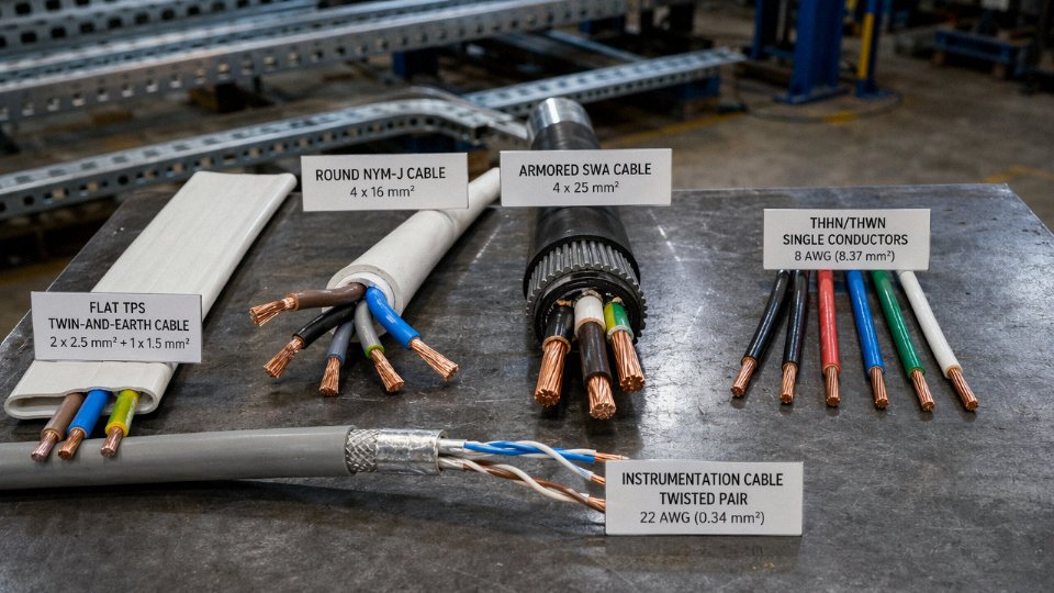
Australian and UK residential installations use flat TPS (twin-and-earth) with a bare or green/yellow earth conductor sitting between the two insulated cores inside a grey PVC outer sheath. North American NM-B (the product most people call “Romex,” though that’s a brand name from Southwire) runs a similar concept — insulated line, neutral, and bare equipment ground — but uses a paper-wrapped bundle inside a nylon-jacketed outer. European NYM-J cable has individually insulated cores including a green/yellow earth, all inside a round grey PVC sheath with a filler to maintain shape. Neutral color coding alone — blue in IEC markets, white or grey in North America — means wiring pulled from one market’s surplus stock into another country’s installation will fail inspection and, more importantly, creates real confusion for maintenance electricians working under a different convention.
TPS, NM-B, and NYM-J cables are interchangeable if the conductor cross-section is equivalentFalse
While conductor ampacity may be similar, sheath material, earth conductor type, color coding, and moisture ratings differ significantly. Using NM-B in a wet location rated for NYM-J, or misreading neutral colors across standards, creates both code violations and genuine safety hazards.
Commercial Buildings: Armor, Conduit, and Fire Rating
Exposed cable runs in commercial mechanical rooms, plant rooms, or above accessible ceilings typically require mechanical protection. In North America that means MC cable (metal-clad, per NEC Article 330) or the older BX armored cable. UK and Australian commercial practice leans on SWA (steel wire armored) for similar duty. The armor isn’t just physical — it often serves as the equipment ground path, which means a compromised armor connection creates a grounding fault that’s invisible until something trips or someone gets a shock.
For raceways and conduit systems, individual THHN/THWN-2 conductors are the standard North American choice, rated 90 °C dry and 75 °C wet. Conduit fill is the limiting factor people underestimate: NEC Chapter 9 tables restrict fill to 40% of conduit interior area for three or more conductors, and on a retrofit project trying to add circuits to existing conduit runs, that limit gets hit surprisingly quickly.
Emergency lighting, fire alarm, and smoke control circuits carry an additional requirement: survival under fire conditions. IEC 60331 specifies circuit integrity testing (typically 30–90 minutes at 750–850 °C depending on the class), and mineral-insulated (MI) cable or appropriately rated LSZH fire-resistant cable is the usual answer. NFPA 72 in North America similarly mandates survivability for fire alarm wiring, which is why you’ll see 2-hour fire-rated cable specified on any commercial job with a real fire engineer reviewing the drawings.
Energy Efficiency Codes Are Driving Conductor Sizes Up
This is a relatively recent shift worth flagging for procurement teams. NEC 2023 and the broader push aligned with IEC 61439 requirements on power distribution assemblies are nudging designers toward upsizing conductors to cut I²R losses on loaded circuits. Practically speaking, 6 mm² is now the frequent choice on 32 A commercial branch circuits where 4 mm² was common five years ago. The energy savings over a building’s lifecycle can justify the upfront copper cost, particularly in facilities running high continuous loads — data centers, commercial kitchens, manufacturing lines. The procurement implication is real: if you’re quoting on a commercial project designed to 2020-era specs and the engineer has since updated to NEC 2023 or local energy codes, your cable quantities and cross-sections may need revisiting before you commit to a price.
Conductor Sizing Quick Reference
| Circuit Type | Typical Current Load | IEC Cross-Section | NEC Equivalent AWG | Typical Insulation | Conduit Fill Note |
|---|---|---|---|---|---|
| General lighting / receptacles | 15–16 A | 1.5–2.5 mm² | 14–12 AWG | PVC / XLPE, 70–90 °C | Max 40% fill, 3+ conductors |
| Kitchen / bathroom circuits | 20 A | 2.5–4 mm² | 12 AWG | PVC / THHN | Derate in conduit bundles |
| Dryer / range circuit | 30–40 A | 6–10 mm² | 10–8 AWG | PVC, rubber or XLPE | Verify derating for 4-wire |
| Service entrance / feeder | 100–200 A | 25–120 mm² | 2 AWG – 4/0 AWG | XLPE, USE-2, SWA | Single-conductor in separate conduit often required |
| Emergency / fire-rated circuit | Varies | 1.5–2.5 mm² typical | 14–12 AWG | LSZH fire-resistant, MI cable | Segregated from general wiring per code |
Ampacity values depend on ambient temperature, installation method, and number of bundled conductors — always verify against the applicable national standard table, not just this reference.
Industrial Control, Instrumentation, and Automation Wiring: Where Signal Integrity Defines the Application
Walk through any operating process plant and you’ll see power cables and control cables running in the same general direction — sometimes on adjacent trays — but they are not interchangeable, and treating them as equivalent is one of the faster ways to generate unexplained trips, nuisance alarms, and the kind of intermittent faults that take a maintenance crew three shifts to chase down.
Power vs. Control Wiring: Same Voltage Class, Completely Different Job
A 230 V AC control circuit feeding a contactor coil operates within the low voltage envelope, but the wire serving it is not a miniature power cable. Control cables — typically 0.75 mm² to 4 mm², multi-core, often individually screened — carry switching signals to PLCs, relay panels, motor starters, and safety interlock systems. They are governed under IEC 60227 (PVC-insulated) and IEC 60245 (rubber-insulated) for the insulation system, and the conductor class matters: a flexible Class 5 conductor inside a marshalling panel behaves very differently under repeated termination stress than a rigid Class 1 conductor does.
The current is usually low, sometimes a few hundred milliamps. The signal, though — that has to arrive clean and at the right moment. Noise tolerance is near zero in a safety-critical interlock.
Shielded Instrumentation Cable and the Grounding Problem Nobody Talks About Enough
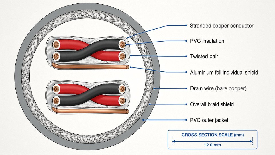
For 4–20 mA analog loops, thermocouple extension wires, and fieldbus protocols like HART or FOUNDATION Fieldbus, you move into instrumentation-grade cable: twisted pairs with individual foil shields, a drain wire, and often an overall braid (coverage typically 85–98% depending on specification). The twist rate and the shield coverage are both engineered, not cosmetic.
In practice, the single most common source of noise-induced signal error in process plants is not the cable itself — it is improper shield grounding. The shield needs a single-point ground, typically at the control room end. Ground it at both ends and you create a ground loop; 50/60 Hz current flows through the drain wire and induces exactly the kind of low-level interference that corrupts a 4 mA signal reading. I’ve seen flow transmitters reading 2–3% high for months because a commissioning technician grounded both ends “to be safe.”
Grounding an instrumentation cable shield at both ends creates a ground loop that introduces 50/60 Hz noise into analog signal circuits.True
A shield grounded at two points with different ground potentials allows induced current to flow through the drain wire, superimposing an AC component onto the signal — a well-documented cause of analog measurement error confirmed by IEC 61000-5-2 and standard instrumentation engineering practice.
Multi-Pair Cable for DCS and PLC Marshalling
When you’re wiring a DCS or large PLC system, pair count selection becomes a procurement and installation decision simultaneously. Standard options run from 2-pair to 40-pair or beyond — individual screened pairs, overall screen, or both. The rule of thumb that holds up in practice: each 4–20 mA loop gets its own twisted pair. Running two loops on the same pair to save cable costs is a decision that looks fine on paper and causes cross-talk problems under load, particularly in dense marshalling cabinets where cable bundles run warm.
Individual drain wires per pair allow selective grounding. An overall drain handles common-mode interference across the whole cable. Whether you need both depends on the noise environment — a motor control center room needs more protection than a clean DCS equipment room does.
Specialty Wire Types the Catalog Lists but the Plant Floor Actually Uses
Silicone-insulated wire rated to 180 °C per IEC 60245-4 is standard inside furnace control panels and kiln wiring — places where PVC would soften and fail within months. It’s more expensive, noticeably so, but the alternative is rewiring a panel annually.
Flexible PUR-sheathed trailing cables for robotic arms and linear axes use Class 5 or Class 6 fine-stranded conductors (IEC 60228) specifically because the copper has to survive tens of millions of flex cycles without work-hardening and fracturing. Using a standard installation cable on a moving axis is a warranty-voiding and ultimately maintenance-generating mistake. Oil-resistant outer sheathing (typically TPE or PUR compound) is non-negotiable in machine tool environments where coolant and cutting oil contact is constant.
Cable Routing and Separation in Industrial Installations
IEC 61000-5-2 recommends a minimum 200 mm separation between unscreened signal/control cables and unscreened power cables running in parallel. In practice, plants often can’t achieve that in congested areas — which is exactly why screened cable exists and why the screening has to be terminated correctly.
In ATEX Zone 1 and Zone 2 hazardous area installations, earthing continuity isn’t a best practice, it’s a compliance requirement. Cable glands must maintain the earth path through the armour or screen, and the installation has to be verified, not assumed. A cable that passes every electrical test but has a compromised armour earth in a Zone 1 area is a safety failure waiting for the right conditions.
Solar PV, Wind, and Battery Storage Systems: Low Voltage Wire in Renewable Energy Infrastructure
Renewable energy installations look straightforward on a single-line diagram. In practice, the cabling environment is one of the harshest you’ll encounter — sustained UV exposure, thermal cycling every single day, DC arcs that won’t self-extinguish, and in wind towers, cables that slowly twist over tens of thousands of operating hours. Choosing “any IEC-rated low voltage cable” and hoping for the best is a procurement error that shows up as ground faults, premature insulation failure, or in the worst case, a rooftop fire.
DC String Wiring: Why Solar-Specific Certification Exists
The wire running panel-to-panel and from string combiner to inverter is called PV wire, solar cable, or more precisely, an EN 50618 (European) or UL 4703 (North American) rated cable. Physically it looks simple — single-core, tinned copper, XLPE or EPR insulation, LSZH outer sheath — but the certification requirements behind that construction are not trivial.
The voltage rating is the first thing to get right. Utility-scale systems increasingly run at 1,500 V DC rather than the older 1,000 V DC standard, because higher DC voltage means fewer parallel strings, smaller combiner boxes, and lower I²R losses in the DC trunk cable. A cable rated 1,000 V AC is not acceptable at 1,500 V DC. DC arcs do not zero-cross. When insulation degrades or a connector fails on an AC circuit, the arc extinguishes itself 100–120 times per second. On a DC circuit at 1,500 V with a 10 A string current, the arc sustains indefinitely until something burns through or a breaker trips. This is why IEC 60364-7-712 and NEC Article 690 both require DC-rated conductors and arc-fault protection on the string side.
EN 50618 specifies a 90 °C continuous / 120 °C short-term temperature rating, UV resistance per IEC 62788-1-4 (typically 1,000+ hours Xenon arc exposure without cracking), and double insulation construction — a primary insulation layer over the conductor plus a separate outer sheath. For rooftop and building-integrated installations, halogen-free sheathing is increasingly required or at minimum strongly advisable; burning PVC cable on a roof produces HCl gas that is corrosive to inverter electronics and genuinely dangerous to fire crews.
Standard building wire (e.g., IEC 60227 PVC-insulated) can be substituted for EN 50618 solar cable on rooftop PV strings if the voltage rating matches.False
Standard PVC building wire lacks the UV stabilization, double insulation, and DC voltage rating required for exposed rooftop PV string wiring. Using it voids certifications, typically violates local electrical codes, and significantly increases the risk of insulation failure within a few years of outdoor exposure.
Battery Energy Storage System Cabling
BESS interconnects are short, brutally high-current runs — think 35 mm² to 150 mm² fine-stranded Class 5 copper, typically orange-sheathed per UN ECE R100 convention for lithium battery systems and IEC 62619 safety requirements. The fine stranding matters because these cables are routed in tight cabinet spaces with small bend radii; solid or coarse-stranded conductors crack at the termination over time from vibration and thermal expansion.
Termination practice here is not optional engineering. Compression lugs, torqued to the manufacturer’s specification (usually somewhere in the 20–50 N·m range depending on lug size and terminal material), are the standard. Loose bolted connections on a 200 A DC bus don’t just fail — they arc, heat, and in a lithium battery cabinet, that’s a thermal runaway scenario. Some battery OEMs now publish specific lug crimp die and torque sequences in their installation manuals; procurement should confirm cable OD tolerance matches the lug barrel before bulk ordering.
Thermal management is a secondary consideration that gets ignored until it causes a derating problem. BESS containers in hot climates can see ambient temperatures of 40–50 °C, and cable bundles running in enclosed trays lose heat slowly. For dense installations, derate cable ampacity accordingly — the 40 °C base temperature assumption in IEC 60364-5-52 tables is optimistic in a container in coastal Qatar in August.
AC Output Side: Inverter to Distribution Board
Once you cross the inverter output terminals, you’re back in familiar IEC 60502-1 XLPE power cable territory. The wrinkle is sizing. NEC 690.8 requires that AC output conductors handle 125% of the inverter’s continuous rated output current, not just the nominal design load. IEC 60364-7-712 has an equivalent requirement. In practice this means a 100 kW inverter outputting at ~430 V three-phase doesn’t get sized at 134 A — you size for 167 A and then apply any additional derating for installation method, ambient temperature, and grouping. Engineers routinely undersize this section of the system because they anchor on the load calculation and forget the renewable-specific multiplier.
Wind Tower Cabling: The Torsion Problem
Inside a wind turbine tower, the cable environment is unlike almost anything else in electrical engineering. The nacelle rotates — continuously, sometimes more than 720° in one direction before the yaw drive unwinds — and the power and control cables that run up the tower must survive this rotation over a 20-year service life. That’s tens of thousands of twist cycles.
The cables used here are trailing or torsion-flex cables: Class 5 (or Class 6) fine-stranded copper, EPR insulation rated for −40 °C to +90 °C (EPR handles cold-weather flexibility far better than XLPE or PVC), and specifically anti-torsion lay in the stranding. Anti-torsion lay means the individual conductors are counter-helically wound so that the cable neither tightens nor loosens under rotation — it remains dimensionally stable. A standard power cable twisted 500 times will begin to birdcage, damaging insulation from the inside. The temperature range is not an exaggeration; tower bases in northern Europe or Inner Mongolia see genuine −30 °C to −40 °C winters, and a cable that goes brittle in the cold will crack the first time the yaw drive kicks in on a January morning.
Offshore array cables connecting turbines to the substation are medium voltage (typically 33 kV), outside the low voltage scope here. But the low voltage control and power cables inside each tower represent significant cable length per unit — a typical 5 MW onshore turbine might use 800–1,500 m of various cable types inside the tower and nacelle — and replacement in a commissioned tower is expensive enough that buying the right cable specification upfront is rarely the wrong decision.
Electric Vehicle Charging Infrastructure and Automotive-Grade Low Voltage Wiring
EV charging is probably the fastest-moving segment in the low voltage cable market right now, and procurement teams that treat it like standard building wire end up with field failures, rejected inspections, or — in the worst case — charging cables that crack and delaminate after one winter in a northern climate parking garage.
Charging Station Supply-Side Cable: Level 1 Through DC Fast Charging
Level 1 charging (120 V / 16 A, roughly 1.4 kW) is the simplest case. A 2.5 mm² XLPE-insulated conductor is typically adequate for the circuit run, and in most jurisdictions you’re working within a standard branch circuit, so the installation cable requirements aren’t dramatically different from residential wiring. Don’t over-engineer it, but don’t undersize the conduit — Level 1 installations often get upgraded later.
Level 2 is where sizing decisions get consequential. At 240 V with draw anywhere from 32 A to 80 A (roughly 7.2 kW to 22 kW), supply conductors typically run 6 mm² to 16 mm², depending on run length, ambient temperature, and whether the conduit is shared. XLPE insulation is the workhouse choice here: it handles the thermal cycling better than standard PVC over a multi-year installation life, and it doesn’t become brittle in the 10–15 °C underground parking structures you find in northern Europe and Canada.
DC fast charging is a different animal. A 350 kW charger at up to 1,000 V DC pulls enough current that supply-side conductors can reach 95 mm², and you’re now firmly in the territory of IEC 61851 and — depending on connector interface — SAE J1772 or CHAdeMO standards governing both the station equipment and the cable assembly. Getting the insulation system wrong on a high-current DC circuit isn’t just a code violation; resistive losses and heat buildup can cause insulation softening at terminations within months.
The Charging Cable Assembly: What Makes It Different From Any Other Flexible Cable
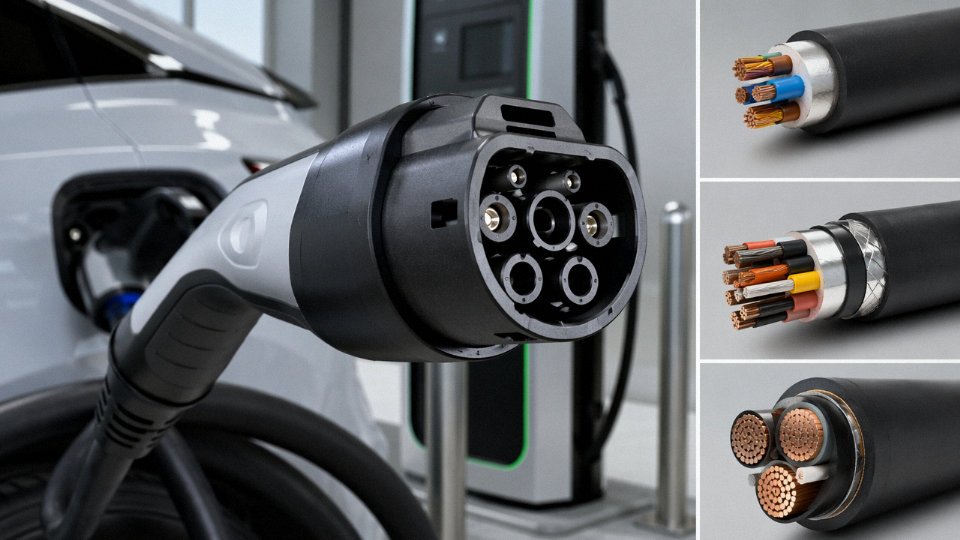
The cable that actually hangs between the station and the vehicle gets abused in ways that fixed installation cable never does. It gets driven over, kinked in sub-zero temperatures, dragged across asphalt, exposed to road salt, motor oil, and UV. Standard flexible building cable fails these conditions quickly.
IEC 62893 sets out the specific requirements for EV charging cable assemblies: Class 5 or Class 6 fine-wire stranded conductors for flexibility, cold-temperature flex testing down to −30 °C (relevant anywhere north of roughly 40° latitude in winter), resistance to oils and UV, and mechanical abrasion ratings appropriate for ground contact. Thermoplastic elastomer (TPE) outer jackets have become the dominant choice over PVC partly for this reason — they stay pliable at low temperatures where PVC would stiffen and eventually crack at the bend point near the connector.
Standard flexible PVC building cable is not suitable for use as an EV charging cable assembly exposed to outdoor conditions and repeated flexing.True
IEC 62893 specifies cold flexibility, oil resistance, UV stability, and mechanical durability requirements that standard PVC flexible cable does not meet. Field use of non-certified cable risks insulation cracking, connector ingress failures, and potential shock hazard.
An operational warning: charging cable assemblies procured outside of UL 2251 (North America) or IEC 62893 (international) certification are a liability problem for charging network operators, not just a technical one. Insurers and utility interconnection agreements increasingly ask for conformance documentation.
Automotive Wire Harnesses: 12 V, 24 V, and the Shift to 48 V
Inside the vehicle, the voltage levels are lower but the environmental demands are arguably more severe than anything you’ll find in a building. Automotive low voltage wire harnesses operate at 12 V (passenger cars), 24 V (commercial trucks and buses), or increasingly 48 V in mild-hybrid architectures. Conductor cross-sections range from roughly 0.13 mm² for sensor signal wires up to 6 mm² for high-current feeds near the battery — and in some heavy truck applications, larger.
Insulation standards here are ISO 6722 and JASO D611, both of which specify thin-wall and ultra-thin-wall constructions that reduce harness mass and diameter compared to industrial cable. Temperature ratings depend heavily on location: 85 °C is typical for body wiring away from heat sources, 105 °C for general under-hood routing, and 125 °C (or higher in specialty grades) for wires routed near the exhaust, engine block, or high-voltage battery pack cooling zones in hybrid vehicles. Getting the temperature class wrong typically shows up as insulation cracking or hardening within two to three years — it’s a warranty return, not an obvious installation failure.
The 48 V mild-hybrid architecture is changing harness economics in a real way. For the same power, 48 V draws roughly a quarter of the current compared to 12 V, which means conductors can be thinner. That’s a meaningful weight reduction across a harness that might contain 40–60 kg of copper in a full-size vehicle. Several OEMs are also substituting aluminum conductors in larger cross-section runs (typically 6 mm² and above) specifically to cut weight. Aluminum works, but the termination details matter enormously: aluminum creeps under bolt torque over thermal cycles, and aluminum-to-copper junctions require bimetallic terminals or antioxidant compound to prevent galvanic corrosion. Skipping that step creates high-resistance connections that generate heat and, eventually, fail.
Procurement Implications for Charging Infrastructure Projects
For bulk procurement of supply-side installation cable going into charging station projects, the relevant compliance checkpoints are local utility interconnection standards — IEEE 1547 applies to grid-tied inverter feeders in the US, for instance — alongside the building and electrical codes governing the facility type. The cable assembly (vehicle-side flexible cable) requires IEC 62893 or UL 2251 certification as a separate procurement line item; it is not interchangeable with the installation cable, and mixing them up is a surprisingly common mistake on projects where a single procurement manager is handling both.
Charging station operators rolling out across multiple countries should verify that their cable assembly supplier can provide documentation for both IEC and regional standards, since a product certified only under one framework may not pass inspection in another jurisdiction.
Direct Burial, Underground, and Outdoor Exposure Applications: When Low Voltage Wire Must Survive the Ground
Underground wiring is not simply “the same cable, buried deeper.” The ground is a chemically active, thermally variable, mechanically unpredictable environment, and treating it otherwise is how projects end up with failed insulation at year three instead of year thirty. Every design decision — cable construction, burial depth, backfill material, corrosion protection — compounds. Get one wrong and the others can’t save you.
Cable Constructions That Actually Belong in the Ground
Four main constructions dominate direct-burial low voltage applications, and they are not interchangeable.
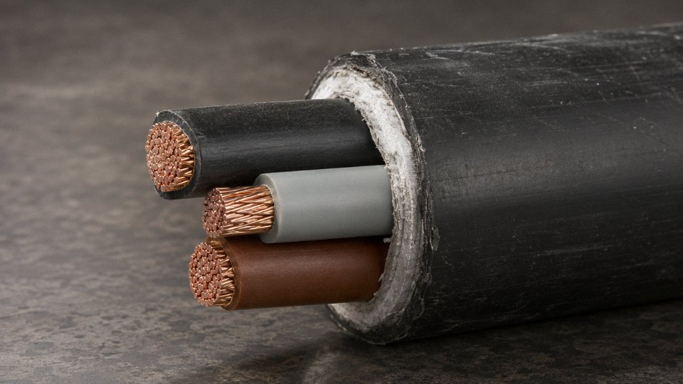
XLPE-insulated, steel wire armored (SWA) cable — designated N2XRY under IEC 60502-1 and its national equivalents — is the workhorse of European and Middle Eastern underground infrastructure. The steel wire armor takes mechanical abuse from backfill settlement, rodent pressure, and incidental digging, while XLPE handles the thermal cycling far better than PVC at elevated load currents. In practice, most specifiers in the Gulf region add a corrugated HDPE outer sheath over the SWA for coastal chloride environments. It adds cost, roughly 8–15% on the cable unit price depending on sheath thickness, but it often eliminates the need for conduit.
USE-2 / RHH / RHW-2 per UL 44 is the North American standard for direct burial. The cross-linked polyethylene insulation handles 90°C wet and dry, and the sunlight-resistance (SR) rating makes it acceptable for the exposed run between grade and the service entrance — a detail inspectors actually check. These cables rely on conductor geometry and insulation quality rather than mechanical armor, so they are typically run in PVC conduit where vehicle loading or rocky soil is a concern.
Flat-armored cable with HDPE outer sheath suits high-moisture environments: river crossings, irrigation zones, coastal reclamation land. The flat armor profile resists the crushing loads that round armor can roll under, and HDPE’s near-zero water vapor transmission rate matters over a 25-year design life in waterlogged clay.
Aluminum-sheathed, lightly armored cable gets specified for rural distribution feeders where installed cost per kilometer dominates the decision. The aluminum sheath provides a degree of moisture protection and doubles as a concentric neutral in some configurations. It works well in stable, dry agricultural soils. In coastal or chemically aggressive ground, it requires real thought — more on that below.
Burial Depth: Minimums Are Not Design Targets
IEC 60364-5-52 Table B.52.2 calls for 0.6 m under residential areas, 0.8 m under driveways, 1.0 m under roadways. NEC Table 300.5 allows 600 mm for USE-2 direct burial and 450 mm in rigid PVC conduit. Experienced specifiers routinely exceed these by 200–300 mm in agricultural areas where subsoiler cultivation equipment routinely operates at 500–600 mm depth, and in cold climates where frost penetration can heave unarmored cables until their bend radius approaches the failure threshold. On one typical industrial park project I’ve seen scoped, the civil engineer added 400 mm to the IEC minimum purely because a future road upgrade was anticipated. That decision costs almost nothing at installation and potentially avoids a complete excavation and replacement.
Soil Thermal Resistivity and Ampacity: The Calculation Engineers Skip
This is the part that gets quietly omitted on smaller projects and causes overloaded cables years after handover.
Soil thermal resistivity (ρ) governs how efficiently heat dissipates from a loaded cable into the surrounding earth. Moist loam runs around ρ = 1.0 K·m/W. Sandy, dry soil — common in arid regions and well-drained embankments — can reach ρ = 2.5 K·m/W or higher. Per IEC 60287, that difference alone can derate a cable’s continuous current rating by 25–35%, depending on burial depth and grouping. A 95 mm² copper N2XRY cable rated at roughly 220–240 A in standard conditions might be limited to 155–175 A in dry sandy ground. Specifying on the standard derating tables without a site-specific soil resistivity measurement is an optimistic assumption that shows up as premature insulation degradation.
The mitigation is thermally stabilized backfill — “thermal sand” or proprietary graded thermal concrete — placed in the immediate cable zone, typically 100–150 mm around the cable. It adds perhaps 3–6% to civil installation cost on a typical run but restores most of the derated ampacity. IEC 60287-3-1 provides the calculation framework. It is worth running.
Soil thermal resistivity (ρ) can reduce buried cable ampacity by 25–35% in dry sandy ground versus moist loam conditions, as calculated under IEC 60287.True
IEC 60287 provides the established methodology for calculating cable current-carrying capacity based on soil thermal resistivity. Sandy dry soil (ρ ≈ 2.5 K·m/W) significantly impedes heat dissipation compared to moist loam (ρ ≈ 1.0 K·m/W), and the resulting ampacity reduction in the 25–35% range is consistent with published derating data from multiple cable manufacturers and IEC reference tables.
Overhead and Tray-Exposed Outdoor Runs
Not every outdoor low voltage installation goes underground. Self-supporting aerial bundled cable (ABC) with a pre-tensioned messenger wire handles the last-mile distribution segment in many rural utility systems — it is significantly cheaper to install than underground in open terrain and easier to inspect and repair. The outer sheath on ABC must carry a genuine UV stabilization package, not just a carbon-black pigment sprinkled into standard PVC. UV degradation in high-irradiance climates — the Middle East, equatorial regions, high-altitude Andean installations — can embrittle a standard PVC sheath within five to seven years.
In enclosed cable bridges and tunnels, LSZH (low smoke, zero halogen) outer sheaths are required under EN 50289 and increasingly demanded by project specifications even where not strictly mandated. The fire performance reason is obvious. Less obvious is that LSZH sheaths in those enclosed environments also simplify maintenance shutdown decisions, since the toxic gas release that forces full evacuation in a halogenated-sheath fire is partially avoided.
Corrosion: The Long-Game Failure Mode
Chloride-rich coastal soils are aggressive toward aluminum sheaths. Steel wire armor in the same environment begins to corrode at mechanical imperfections in the bitumen coating within eight to twelve years in some tropical coastal sites. The usual mitigations are a sacrificial zinc anode system for long cable runs (spaced at intervals calculated from soil resistivity and the anode consumption rate), impressed current cathodic protection for major infrastructure, and corrosion-inhibiting compound-filled conduit for shorter critical runs.
Stray DC current from traction systems — metro lines, light rail, electrified freight rail — creates a subtler problem: electrochemical corrosion on buried conductors running parallel to the rail route. The mechanism is well established and the risk is proportional to the current density and soil conductivity. On projects within roughly 500–1,000 m of a DC traction system, the design should include an assessment against EN 50162 (protection of structures from stray current corrosion). Ignoring it on a long feeder run in an urban rail corridor is, in my experience, the kind of decision that produces a corrosion failure at year eight and a contract dispute about who specified what.
| Soil / Environment | Primary Threat | Preferred Cable Construction | Key Mitigation |
|---|---|---|---|
| Moist agricultural loam | Mechanical damage, rodents | SWA N2XRY or armored USE-2 in conduit | Exceed NEC/IEC depth minimum by 200–400 mm |
| Dry sandy soil (arid) | Thermal derating, UV at entry point | N2XRY + thermal sand backfill | IEC 60287 ampacity calculation, thermal backfill |
| Coastal / chloride-rich | Aluminum/steel sheath corrosion | HDPE-sheathed SWA or plastic-sheathed flat armor | Sacrificial anodes, avoid aluminum sheath |
| Near DC traction systems | Stray current electrochemical corrosion | PVC or HDPE-sheathed copper, no bare aluminum sheath | EN 50162 assessment, insulated joints |
| Enclosed cable bridge/tunnel | Fire/smoke in armored runs | LSZH outer sheath, armored | EN 50289 compliance, segregated cable trays |
A general operational warning: never backfill directly over an unprotected cable with sharp granular material, regardless of armor specification. Angular stone or recycled concrete rubble concentrated under mechanical load will work through even SWA over five to ten years of ground movement. A 100 mm layer of compacted fine sand under and above the cable before general backfill is cheap insurance — and it is frequently omitted on rushed civil contracts.
Selecting the Right Low Voltage Wire: A Procurement and Engineering Decision Framework
Getting the specification wrong costs more than the cable. Rework, re-pulling, failed inspections, or a derated circuit that trips on the first hot summer day — these are the real consequences of skipping a structured selection process. What follows is a five-step sequence that integrates electrical, mechanical, environmental, and commercial variables into a defensible cable spec before you issue a purchase order.
Step 1: Confirm System Voltage and Fault Level
Start here, not at the conductor size. Verify that a 0.6/1 kV rated cable is genuinely sufficient for your system’s maximum sustained voltage and prospective fault current. Most low voltage distribution networks sit comfortably within this envelope, but some industrial bus systems — particularly in mining or heavy process plants — can push transient overvoltages that argue for reviewing insulation class carefully. If your fault level is high enough that the cable’s short-circuit withstand capacity becomes a sizing constraint, that needs to enter the calculation before anything else.
Step 2: Calculate Design Current and Apply Derating — All of It
This is where most procurement-level specs go wrong. Engineers will size a conductor for its rated current in free air and stop there.
Derating factors stack multiplicatively, not additively. Take a worked example: four 3-core cables, 35 mm² Cu XLPE, laid flat and touching on a cable tray. Per IEC 60364-5-52, the grouping factor for four circuits in that arrangement is roughly 0.65. Ambient temperature is 45 °C rather than the reference 30 °C, giving a temperature correction factor of approximately 0.87. Combined derating is 0.65 × 0.87 = 0.565. A cable rated at 154 A in free air is now limited to around 87 A in this installation — a 44% reduction. That’s the gap that causes nuisance tripping, accelerated insulation aging, and eventually a fire risk nobody wants to explain to an insurer.
Grouping is consistently the most underestimated variable in the plants I’ve seen. Burial depth and soil thermal resistivity matter too for direct-buried runs, especially in clay-heavy soils that hold heat.
Step 3: Check Voltage Drop and Upsize If Needed
IEC guidance recommends no more than 3% voltage drop on final circuits, with a 5% maximum from the origin of the installation to any point of use. Run the calculation at full design current, not a reduced estimate. For long feeders — a 200 m run to a remote pump station, say — you’ll often find that voltage drop forces you up one or two conductor sizes beyond what thermal capacity alone requires. Size for the constraint that actually governs, not the one that’s easiest to calculate.
Step 4: Define the Environmental Class
Nail down IP rating, UV exposure, chemical environment (oils, acids, ozone), mechanical loading (armored vs. unarmored, flexible vs. fixed), and operating temperature range. An LSZH sheath is mandatory in tunnels, confined cable routes, and public buildings in most markets. A standard PVC outer jacket is fine in a dry indoor panel. Getting these backwards creates a real problem — standard PVC becomes brittle and cracks in sustained UV exposure within two to four years depending on climate, and that’s a maintenance headache you don’t want on a rooftop solar installation.
Step 5: Confirm the Required Certification Mark
Destination market drives this entirely. UL listing for North America, CE marking with relevant harmonized standards for Europe, CCC for China, SASO for Saudi Arabia, GOST-R for Russia and much of Central Asia, BIS for India. Specifying the right mark upfront avoids the expensive problem of cables arriving on-site that customs or the local electrical inspector will not accept.
Copper vs. Aluminum: The Procurement Trade-off at Scale
Copper’s conductivity (roughly 58 MS/m) versus aluminum’s (around 35 MS/m) means aluminum needs a larger cross-section to carry the same current — typically one or two sizes up. But aluminum is 30–40% lighter and roughly 50–60% lower cost per unit length for equivalent current capacity at cross-sections of 50 mm² and above. On long feeders and overhead distribution runs where voltage drop is manageable and termination is done by experienced crews using proper compression lugs, aluminum makes economic sense. For control panels, intricate conduit runs, and anything under 35 mm² where termination reliability and conduit fill matter more, copper is usually the right call. The decision is genuinely application-specific — anyone who tells you one answer fits all scenarios is selling something.
Supply Chain and Lead Time Realities
Standard PVC/SWA power cables in common cross-sections (roughly 4 mm² through 240 mm²) are typically ex-stock or available within two to four weeks from a manufacturer running multiple production lines. Specialty constructions — LSZH armored, high-flex continuous-flex rated, mineral-insulated — realistically run 8 to 20 weeks from order depending on conductor size, quantity, and current production loading. For large projects, frame agreements with factory-direct pricing and batch-level test certificate traceability are worth negotiating explicitly. Jinda’s five production bases across China allow staggered batch scheduling that can meaningfully compress lead times on multi-item project lists, compared with sourcing from separate specialized suppliers.
Derating factor stacking (grouping × temperature) can reduce a cable's usable current capacity by more than 40% compared to its free-air ratingTrue
Per IEC 60364-5-52, correction factors are applied multiplicatively. A grouping factor of 0.65 combined with a 45°C ambient temperature factor of 0.87 yields a combined factor of approximately 0.565, reducing a 154 A free-air rating to roughly 87 A — a 43–44% reduction.
Application Specification Reference Table
| Application | Standard | Conductor Size Range | Insulation | Armoring | Certification |
|---|---|---|---|---|---|
| Residential branch circuit | IEC 60227 / NEC | 1.5–6 mm² Cu | PVC | None | CE / UL / CCC |
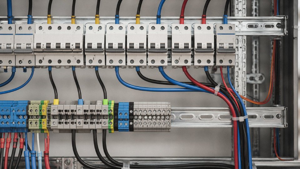
| Industrial control panel | IEC 60228 | 0.5–4 mm² Cu | PVC or LSZH | None | CE / UL |
| Solar DC string | IEC 62930 / EN 50618 | 4–10 mm² Cu | XLPE/HEPR | None | TÜV / UL 4703 |
| EV Level 2 supply | IEC 62893 | 6–16 mm² Cu | Flexible XLPE | None (flexible) | CE / UL |
| Direct burial feeder | IEC 60502-1 | 16–240 mm² Cu or Al | XLPE | SWA or steel tape | CE / local utility |
| Outdoor cable tray | IEC 60502-1 | 4–185 mm² Cu or Al | XLPE + UV PVC | Optional AWA | CE / CCC |
| Flexible machine connection | IEC 60245 | 0.75–35 mm² Cu | Flexible PVC | None | CE |
| LSZH tunnel installation | IEC 60332-3 | 4–185 mm² Cu | XLPE + LSZH | SWA | CE + IEC 60332 |
Conductor size ranges shown are typical starting points; actual sizing depends on load, run length, and derating factors calculated per Steps 2 and 3 above.
Frequently Asked Questions About Low Voltage Wire Applications
Can I use standard building wire (NM-B or NYM) outdoors or underground?
No — and this comes up more often than it should. NM-B and NYM are designed for dry interior locations. They have no UV stabilization, no moisture-barrier layer, and their outer sheaths will degrade within a season or two of outdoor exposure. Underground, ground moisture migrates into the insulation, leading to insulation resistance failures that show up as nuisance tripping or, worse, undetected leakage current. Direct burial requires USE-2, URD, or armored SWA cable rated for wet locations. Exposed outdoor runs need a sunlight-resistant (SR) rated cable or must run in conduit. Using interior-rated wire outside is a code violation and a genuine fire and shock hazard, not a paperwork issue.
What is the difference between a low voltage wire and a low voltage cable?
In common industry usage, “wire” means a single insulated conductor; “cable” is two or more conductors assembled under a common outer sheath. In practice, IEC and NEC documents use both terms loosely and inconsistently, which creates real confusion during procurement. The safe habit is to always specify by construction description and the relevant standard number — not by what someone called it in a sales sheet. “4 mm² single-core, 0.6/1 kV, IEC 60502-1” is unambiguous. “Low voltage wire” by itself is not a specification.
How do I specify conductor cross-section for a solar DC string?
Start with the string short-circuit current (Isc) at STC, multiply by 1.25 per IEC 60364-7-712, then apply derating for ambient temperature and cable grouping. Select the next standard cross-section from the IEC 60228 series — 2.5, 4, 6, 10, 16 mm² are the typical steps. Most residential string installations land on 4 mm² or 6 mm² PV wire rated for 1,500 V DC. Rooftop installations in hot climates (ambient regularly above 40 °C, cables lying on dark roofing membrane) need an additional derating pass — skipping that step on a large array can mean years of accelerated insulation aging before anyone notices.
Is aluminum wire safe for residential use?
At ≥50 mm² — service entrances, sub-panel feeders — aluminum is widely used and perfectly safe, provided you use AL-rated terminations and apply anti-oxidant compound at every connection. The problem is small-gauge aluminum (AWG 12–10 range) in branch circuits, which has a documented history of overheating at loose connections. Many residential codes either prohibit it or restrict it to specific applications. Always verify with the local authority having jurisdiction before specifying.
What certifications should I require when importing low voltage cable?
Destination market dictates the answer: UL 83 / UL 44 / UL 4703 for North America; CE with a CPR Declaration of Performance for the EU; CCC for sale within China; SASO for Saudi Arabia; BIS IS 1554 for India; GOST-R for Russia and CIS markets. Reputable manufacturers — Jinda included — can supply batch test certificates, third-party reports from SGS, TÜV, or Intertek, and mill certificates traceable to the specific production run. If a supplier cannot produce traceable documentation, that is a red flag regardless of price.
Jinda supplies third-party witnessed test reports and mill certificates traceable to each production run for export orders.True
Integrated manufacturers with in-house QC labs and established third-party auditor relationships routinely provide this documentation; it is standard practice for compliant export cable supply.
How much voltage drop is acceptable?
IEC 60364-5-52 recommends no more than 3% for lighting circuits and 5% for power circuits, measured from the supply transformer to the load. NEC recommends the same thresholds but does not mandate them. In solar PV DC wiring, most designers target 1–2% to protect energy yield — on a 1 MW array, the difference between 1% and 3% DC-side losses is real money over a 25-year asset life. Voltage drop is proportional to current and conductor length, inversely proportional to cross-section. Longer runs almost always justify stepping up one conductor size.
When is LSZH wire actually required?
Anywhere dense smoke or corrosive gas would kill people or destroy equipment faster than the fire itself: tunnels, metro systems, ships, offshore platforms, data centers, high-occupancy buildings. Standard PVC releases hydrogen chloride (HCl) when it burns — toxic, corrosive to electronics, and it turns evacuation corridors into black-out zones within minutes. LSZH insulation per IEC 60754-1/2 and EN 50267 dramatically cuts both hazards. Specific mandates come from EN 45545 for railway rolling stock, IEEE 1202 for power station cables, and project-specific owner specifications. In my experience, specifiers often forget LSZH on the secondary distribution inside a facility while correctly specifying it on the main runs — a gap worth closing during design review.
Can Jinda supply non-standard cross-sections, custom colors, or special drum lengths?
Yes. With 470,000 m² of production capacity across five bases in China, Jinda handles made-to-order requirements routinely: non-standard conductor cross-sections, custom sheath colors (orange for EV/HV circuits, red for fire alarm, white for clean-room environments), drum lengths from 100 m coils up to 3,000 m steel drums, and bespoke multi-core configurations. Factory inspection, third-party witnessing, and complete documentation packages — test reports, material certificates, packing lists — are standard for export orders, not extras you need to negotiate for.




