Wiring a machine wrong — or specifying the wrong cable type at procurement — rarely announces itself until something fails. A relay panel fed with power cable instead of proper screened control cable picks up enough electrical noise to misfire actuators; a conveyor stops mid-shift; the maintenance crew spends four hours chasing a fault that was built into the specification from the start. That kind of downtime compounds fast, and in high-cycle automation environments the cost is rarely just the repair.
A control cable is a multi-core electrical cable designed to carry low-level signals, switching commands, and control voltages — typically 300/500 V up to 450/750 V, occasionally 0.6/1 kV for heavier industrial duty — between control panels, sensors, actuators, and field devices. Unlike power cables, control cables prioritize signal integrity, mechanical flexibility, and often electromagnetic shielding over current-carrying capacity.
What makes control cable selection genuinely complicated is how many variables converge at once: core count, cross-section, shield type, jacket material, flex rating, the installation environment. Get any one of those wrong and you either have a safety problem or a slow-burning reliability problem that only shows up under load, in summer heat, or after the cable has flexed a few thousand cycles too many. The rest of this article works through each of those decisions in the order a procurement engineer or panel designer actually encounters them.
Core Construction Layers: Conductors, Insulation, Shielding, and Jackets Explained
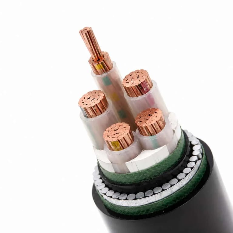
Understanding what’s inside a control cable isn’t academic — it’s what separates a procurement decision that holds up for fifteen years from one that causes a warranty dispute after the first summer.
Conductors
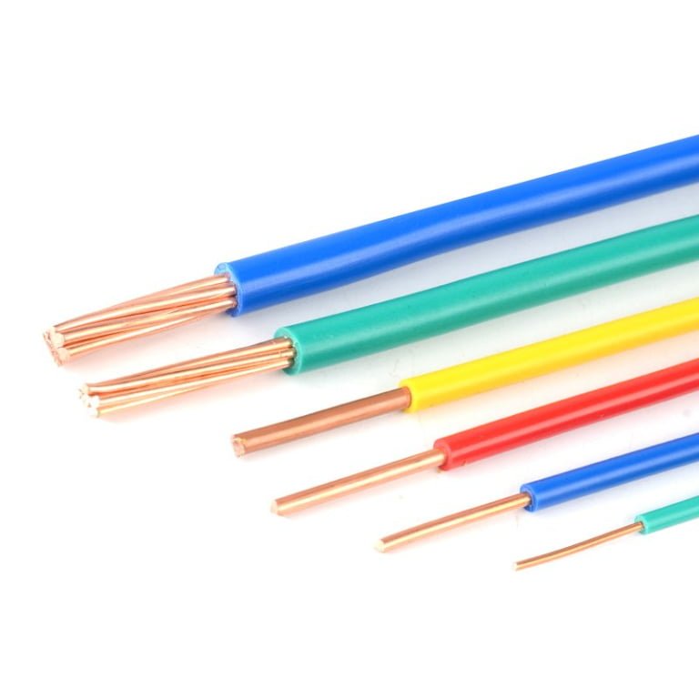
Most control cables use plain annealed copper, though tinned conductors are worth specifying in humid or coastal environments where bare copper oxidizes at termination points and drives up contact resistance over time. Class 2 stranded construction (per IEC 60228) is the default for almost everything in panel wiring and field runs — it tolerates repeated flexing during installation and survives the inevitable “just pull it a bit tighter” moments that happen on every job site.
Cross-sections run from 0.5 mm² up to 10 mm², but in practice the vast majority of industrial procurement clusters around 0.75 mm², 1.5 mm², and 2.5 mm². The 0.75 mm² cores handle most instrumentation and low-current signal circuits; 1.5 mm² is the workhorse for control logic wiring where you’re switching 24 V DC or 230 V AC through relay contacts; 2.5 mm² starts appearing when the control cable is also carrying motor feedback or solenoid coil currents above roughly 10 A. Anything larger than 4 mm² in a control cable is unusual enough that you should double-check whether a power cable wouldn’t be the right call.
Core Insulation
PVC is still the workhorse — rated to 70 °C, inexpensive, readily available in every color under the sun, and perfectly adequate for dry indoor installations. Its weaknesses are well known: it gets brittle below about -15 °C, it softens and can deform under sustained heat near motor housings, and it releases hydrogen chloride when it burns.
XLPE (cross-linked polyethylene) steps up to 90 °C, handles aggressive chemicals better, and maintains mechanical integrity across a wider temperature swing. Expect to pay roughly 15–30% more per meter depending on core count and shield configuration — the premium is real but usually justifiable on outdoor runs or anywhere near process heat.
LSZH (low smoke zero halogen) is increasingly mandated rather than merely preferred in tunnels, railway rolling stock, data centers, and offshore platforms. It burns more slowly and without the toxic halogen gases that make PVC dangerous in confined evacuations. It is also less flexible than PVC at low temperatures, which matters if you’re pulling cables through conduit in an unheated building in January.
LSZH insulation is required by IEC 60332-3 for cables installed in grouped bunches in confined or public spacesTrue
IEC 60332-3 specifies flame propagation tests for bunched cables; LSZH materials are commonly required to meet the emission and smoke density limits set by this and related standards such as IEC 61034 and IEC 60754.
Core Identification
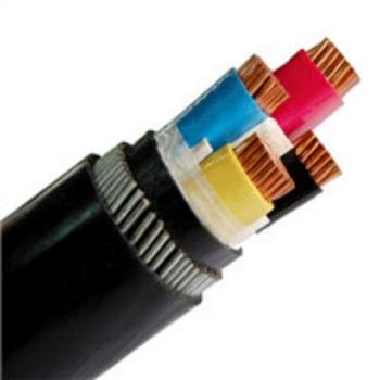
For cables up to about five or seven cores, color-coded insulation following IEC 60446 conventions is standard. Beyond that, numbered cores are the practical answer — no one can reliably distinguish fifteen different color variations under a cabinet’s fluorescent light at midnight during a commissioning push. Consistent, readable core identification genuinely reduces wiring errors and cuts commissioning time. That’s not a vague claim; a misidentified core in a safety interlock circuit is a real incident waiting to happen.
Shielding Options
This is where a lot of specification errors occur, usually in the direction of under-shielding.
Unshielded cables (SY-type in European nomenclature) are fine for hardwired control circuits in a clean electrical environment — think basic relay logic in a small panel, away from variable frequency drives or high-current switching. Once you introduce VFDs, servo drives, or any kind of analog signal alongside digital wiring, you need shielding.
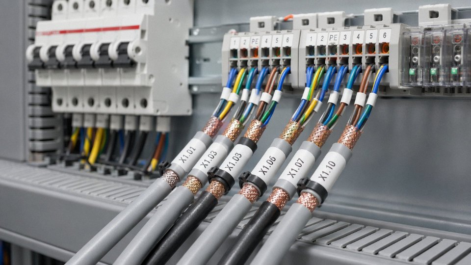
Individual pair or triad foil shields (aluminum-polyester laminate) provide the most targeted protection for multi-pair instrumentation cables, isolating each circuit from its neighbors. An overall foil shield gives reasonable coverage against external radiated interference without adding much diameter or cost. Braided copper shields have lower transfer impedance at higher frequencies and are better grounded at terminations — they’re the right choice when the cable runs near power busbars or through heavy industrial EMI environments. Combined foil-plus-braid is the belt-and-suspenders option for analog signals in genuinely noisy plants; it costs more and adds stiffness, but it’s the correct answer for 4–20 mA loops routed near drives.
Bedding, Armoring, and Outer Jacket
Steel wire armoring (SWA) is specified for direct burial, mechanical abuse in cable trays, or anywhere a forklift might conceivably drive over a cable run. Steel tape armoring (STA) is lighter and cheaper but only handles radial crush loads — it won’t stop a sharp impact. For light-duty indoor trays without mechanical hazard, neither is necessary.
The outer jacket material depends on the environment. PVC is fine for most indoor and sheltered outdoor applications. PUR (polyurethane) is significantly more resistant to oils, cutting fluids, and abrasion — it’s common in machine tool and food processing installations. LSZH outer sheaths follow the same logic as LSZH insulation: mandated in confined spaces and public infrastructure.
Jacket color carries real operational meaning. Black is the conventional outdoor and buried service color in most markets. Gray is the indoor/panel standard across European industrial practice. Orange signals high-visibility hazardous locations or mining cables in several international conventions. Specifying the wrong jacket color doesn’t break anything immediately, but it creates confusion during maintenance and can cause compliance issues on regulated sites.
| Construction Element | Material Options | Key Standard | Typical Use Case |
|---|---|---|---|
| Conductor | Plain or tinned annealed copper, Class 2 stranded | IEC 60228 | Panel wiring, field instrumentation, control loops |
| Core insulation | PVC (70 °C), XLPE (90 °C), LSZH | IEC 60502, IEC 60332 | PVC: general indoor; XLPE: elevated temp/chemical; LSZH: confined/public spaces |
| Core identification | Color-coded (≤7 cores) or numbered (>7 cores) | IEC 60446, DIN VDE 0293 | Commissioning accuracy, fault tracing, maintenance |
| Shielding | Unshielded, foil (Al-PET), overall braid, foil+braid | IEC 60096, EN 50288 | EMI sensitivity, signal type, proximity to drives |
| Bedding/armor | SWA, STA, unarmored | IEC 60502-1 | Direct burial, tray, conduit, indoor panel |
| Outer jacket | PVC, PUR, LSZH | IEC 60227, IEC 60332-3 | Chemical resistance, abrasion, fire regulation |
International Standards and Approvals That Govern Control Cable Selection
Specifying the wrong standard for a destination market isn’t a paperwork problem — it’s a re-procurement event that can stall a commissioning schedule by weeks. Getting the standards right at the RFQ stage is cheaper than any other time.
IEC 60227 and IEC 60502-1: Know Which Series Actually Applies
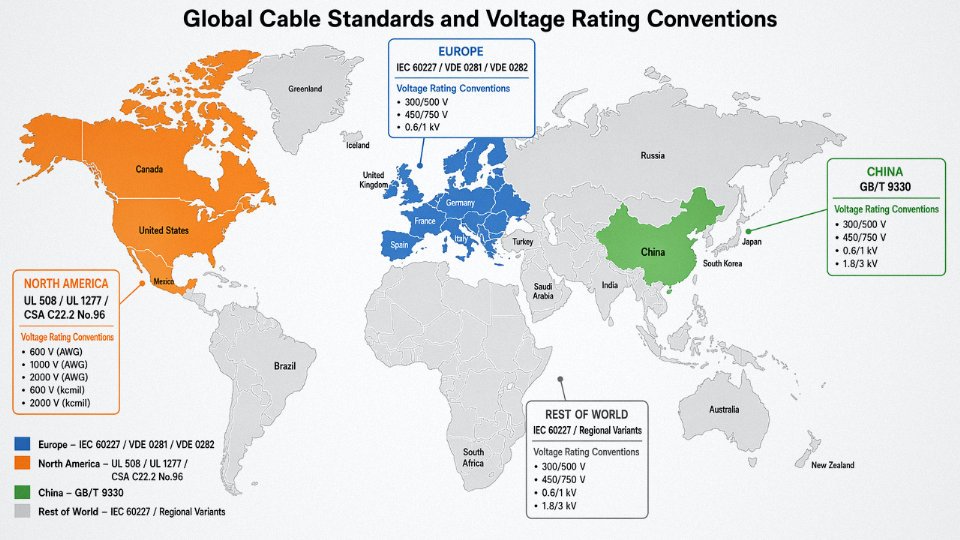
These two IEC series confuse a surprising number of procurement engineers. IEC 60227 covers PVC-insulated cables rated up to 450/750 V — this is the series that directly governs the majority of general-purpose control cables used in automation panels, motor control centers, and instrumentation loops. IEC 60502-1 covers power cables with extruded insulation (PVC or XLPE) rated from 1 kV upward, so for a 0.6/1 kV control cable sitting at the upper end of the voltage range, you may find yourself in a grey zone where both series get referenced depending on the insulation system. The practical rule: if your control cable is below 1 kV and PVC-insulated, IEC 60227 is your primary reference. XLPE-insulated control cables approaching 1 kV often get specified under IEC 60502-1 conventions, particularly in European power-generation projects.
VDE 0281 and VDE 0282: Why European Project Engineers Call Out Type Names
German standards VDE 0281 (PVC-insulated) and VDE 0282 introduced the alphanumeric type designation system that became the de facto specification language across European projects. When an engineering contractor in Germany, the Netherlands, or Poland writes “YSLY-JZ 7G1.5” or “YSLCY-OB 4×1.0” into a cable schedule, they are not being arbitrary — each letter encodes insulation material, sheath type, conductor arrangement, and shielding configuration. Chinese manufacturers supplying European projects must be able to cross-reference these type codes fluently against their own construction parameters. A mismatch in sheath material or conductor stranding class, even if it looks minor on a datasheet, can trigger rejection at factory acceptance testing. In practice, this cross-referencing capability separates manufacturers who genuinely serve export markets from those who are simply repackaging domestic product.
UL 508 and CSA C22.2 No. 96: North American Projects Operate on Different Rules
North American projects specify AWG conductor sizing (typically AWG 22 down to AWG 10 for control applications), 600 V ratings, and require cables to carry an active UL listing — not just compliance, but listing. UL 508 governs industrial control equipment and informs the cable requirements inside panels; the cable itself typically needs to be listed under UL 508 or relevant UL standards such as UL 1277 for instrumentation tray cable. CSA C22.2 No. 96 is the Canadian parallel. If a cable destined for a Texas chemical plant or an Ontario automotive line ships without UL/CSA marks, it will not pass the AHJ (authority having jurisdiction) inspection. Full stop.
GB/T 9330: The Chinese National Standard and Its Export Relationship
GB/T 9330 is the Chinese national standard covering plastic-insulated control cables and defines the baseline construction — conductor class, insulation thickness tolerances, core identification, and test methods — against which domestic production is measured. Jinda’s manufacturing processes are aligned with GB/T 9330, but export production is regularly specified and tested to IEC 60227, VDE types, or customer-defined standards. The standards are broadly compatible at a construction level, but differences exist in test voltages, sheath thickness tables, and conductor resistance limits that matter at the acceptance stage.
GB/T 9330 and IEC 60227 are structurally similar enough that a cable compliant with GB/T 9330 will typically meet IEC 60227 requirements in most tested parameters, though formal third-party IEC test reports are still required for international project documentation.True
Both standards share technical roots, but project owners and EPCs in international markets require documented IEC compliance, not assumed equivalence. Test reports from accredited labs are the accepted evidence.
Marine and Offshore Approvals: Stricter Than You Expect
DNV (Det Norske Veritas), Lloyd’s Register, Bureau Veritas, and ABS each maintain their own type-approval programs for shipboard and offshore cables. The requirements go beyond standard IEC flame retardancy — halogen-free sheath compounds, specific smoke density and toxicity limits, and cold-bend performance at −40 °C are routine demands. A cable that passes IEC 60332-3 flame spread testing can still fail a marine approval test on smoke opacity. Type approval must be issued specifically to the manufacturer and cable construction; it is not transferable. Vessels and platforms operating under flag-state requirements will name the approved manufacturer in their documentation.
ATEX and IECEx: What the Hazardous Area Requirements Actually Mean for Cable Selection
Control cables themselves do not carry ATEX or IECEx certification — those certifications apply to equipment with ignition risk (motors, switches, junction boxes). What hazardous-area installations do require is that cables meet specific construction characteristics compatible with the zone classification: armoring appropriate for mechanical protection, sheath materials that don’t generate static in Zone 1/2 environments, temperature ratings that stay within the T-class of the system, and in many cases, compliance with IEC 60079-14 installation standard requirements. An unarmored PVC-sheathed cable is not automatically excluded from Zone 2, but the system designer bears responsibility for demonstrating that the construction is suitable. Get this wrong and the consequences range from an insurance void to a regulatory shutdown.
Standards Quick-Reference Table
| Standard / Approval | Issuing Body | Primary Region | Key Requirement |
|---|---|---|---|
| IEC 60227 | IEC | Global | PVC-insulated cables ≤ 450/750 V; core insulation and sheath test methods |
| IEC 60502-1 | IEC | Global | Extruded insulation cables 1 kV and above; XLPE and PVC power/control |
| VDE 0281 / VDE 0282 | VDE (Germany) | Europe | Type designation system (YSLY, YSLCY, etc.); widely used in European project specs |
| UL 508 / UL 1277 | UL (USA) | North America | Active UL listing; AWG sizing; 600 V rating; mandatory for AHJ inspection |
| CSA C22.2 No. 96 | CSA | Canada | Canadian equivalent of UL requirements; required for Canadian installations |
| GB/T 9330 | SAC (China) | China | Domestic production baseline; insulation/sheath thickness, conductor resistance |
| DNV / LR / BV / ABS | Classification societies | Marine / Offshore | Halogen-free, smoke/toxicity limits, cold-bend performance; manufacturer-specific type approval |
| IECEx / ATEX | IECEx / EU | Hazardous areas | Cable construction compatibility with zone classification; not a cable certification per se |
Control Cable Types by Application: Flexible, Shielded, Armored, and High-Flex Variants
Understanding what a control cable is gets you halfway there. The harder question — and the one that actually drives procurement decisions — is which type belongs in your specific installation. Get this wrong and you’re looking at nuisance trips, premature cable failure, or a re-pull job that costs ten times what the right cable would have.
Fixed Installation Cable: The Workhorse Majority
For static routing in cable trays, conduits, and marshalling panels, an unshielded or lightly shielded multi-core cable like YSLY or NYY-J is usually the correct and most cost-effective choice. These cables use Class 2 stranded conductors, a PVC or XLPE insulation system, and an overall PVC jacket — robust enough for decades of service in a dry or moderately humid environment when they’re not being flexed, dragged, or exposed to chemicals. Building automation systems, substation interlock wiring, and process plant I/O loops running to conventional relay or PLC panels are all natural territory. Core counts from 4 to 19 cover the vast majority of these applications, though runs to large junction boxes sometimes push into 24- or 37-core territory.
Shielded Cable in EMI-Dense Environments
The moment you introduce variable-frequency drives, servo amplifiers, welding stations, or high-speed switching gear into the picture, unshielded control cable becomes a liability. Induced noise couples into unshielded conductors and can cause false triggers, erratic PLC inputs, or corrupted encoder feedback — faults that are genuinely difficult to diagnose and often get blamed on the controller before anyone checks the cable.
Screened variants like YSLCY (with a braided copper shield) or YSLYCY (with an individual core screen plus an overall braid) provide a low-impedance return path for induced currents and reduce radiated EMI to adjacent circuits. The shield must be terminated correctly — single-point earthing for low-frequency applications, both-ends earthing in high-frequency drive environments — because a floating or poorly bonded shield can actually worsen noise performance. This detail gets missed more often than it should in panel builds done under schedule pressure.
Armored Cable for Mechanical and Environmental Hazard
Steel wire armored (SWA) or steel tape armored control cables — often supplied as SY or CY variants with armoring added — are the right call for direct burial, outdoor trenched routes, underground pits, and areas where mechanical damage or rodent attack is plausible. The armoring also adds meaningful tensile strength, which matters in vertical runs down deep shafts or on cable ladders where the cable weight becomes a real load. In my experience, projects in food processing plants and outdoor substations routinely underspecify armoring on the assumption that conduit protection is adequate; a single excavator strike or a rodent gnaw-through changes that calculation fast.
High-Flex and Continuous-Flex Cable
Standard PVC-jacketed cable with Class 2 conductors will fatigue and fracture inside a cable track or on a robot arm — sometimes within weeks under aggressive duty cycles. High-flex cables use fine-stranded Class 5 or Class 6 conductors, specially compounded PUR (polyurethane) jackets, and fillers engineered to prevent core migration under repeated bending. Rated cycle lives of 5 million to 10 million flexing cycles are realistic for quality PUR cables, versus a few hundred thousand at best for standard constructions. The jacket compound matters as much as the conductor stranding; PUR resists abrasion and tearing in cable chain applications far better than PVC.
Standard PVC control cables will fail prematurely in continuous-flex cable track applicationsTrue
Standard PVC-insulated cables use Class 2 conductors and rigid PVC compounds not designed for repeated bending. In energy chain or robotic axis duty, conductor fatigue fractures and insulation cracking develop within a fraction of the service life achieved by purpose-built Class 5/6 fine-stranded PUR cables.
Oil-Resistant and Chemical-Resistant Variants
Machine tools, mobile hydraulic equipment, and chemical processing lines expose cable jackets to cutting fluids, hydraulic oil, solvents, and cleaning agents that swell or crack standard PVC within months. PUR-jacketed cables or cables using special oil-resistant PVC compounds (sometimes designated with an “-C” suffix in German nomenclature) hold up where standard grades fail visibly. The distinction matters for outdoor mobile equipment especially, where UV exposure compounds the degradation.
LSZH/LSOH Cable for Fire-Critical Installations
In tunnels, offshore platforms, mass-transit systems, and data centers, the hazard in a cable fire is rarely the flame itself — it’s the dense toxic smoke and halogen acid gases that standard PVC releases when burning. EN 60754 covers halogen content, EN 61034 governs smoke density, and the IEC 60332 series addresses flame propagation. LSZH (low-smoke zero-halogen) or LSOH cable compounds meet these thresholds, and specifying them is increasingly a code requirement rather than an option in these occupancies. The mechanical properties of LSZH compounds are generally softer than PVC, so LSZH cables in high-flex applications need to be specifically rated for that duty — not all LSZH jackets are.
Selecting the Right Type: A Practical Decision Sequence
Work through these questions in order and you’ll land on the correct cable type without over-specifying or under-specifying:
- Voltage class first — 300/500 V covers most control and interlock circuits; step up to 450/750 V or 0.6/1 kV only if the system voltage or national standard requires it
- Fixed or moving installation — any repeated flexing, cable chain, or robotic application immediately points to high-flex PUR; everything else continues down the list
- EMI environment — VFDs, servo drives, or welding equipment present? Screened cable is not optional
- Mechanical hazard — direct burial, outdoor exposure, rodent risk, or tensile loading on vertical runs? Add armoring
- Fire and smoke regulation — tunnel, offshore, transit, or data center? LSZH/LSOH is likely mandatory; confirm the applicable standard for your jurisdiction
- Chemical exposure — hydraulic fluid, coolant, or solvent contact? Specify PUR or oil-resistant PVC jacket compound explicitly
- Temperature range — standard PVC works from roughly −20 °C to +70 °C; PUR extends the low end; XLPE or silicone compounds handle elevated temperatures in furnace areas or engine rooms
Working through this sequence takes ten minutes and prevents the kind of mid-project re-specification that delays commissioning and strains supplier relationships.
Where Control Cables Are Installed: Industry Sectors and Specific Circuit Examples
Control cables are everywhere once you start looking for them — bundled in cable trays behind PLC racks, buried in conduit under refinery pipe racks, laced through cable chains on robot arms. The variety of deployment contexts is genuinely wide, and the installation challenges in each sector are different enough that a cable well-suited to one environment can fail quickly in another.
Industrial Automation and Manufacturing
This is where most engineers first encounter control cable. PLC I/O wiring, motor starter interlocks, conveyor drive enable circuits, end-of-line vision sensor feedback — all of it runs on control cable. A mid-size automotive assembly plant, say a body shop and trim line combined, can contain somewhere between 50 and 200 km of control cable across its PLC racks, safety relay panels, and distributed I/O nodes. That range depends heavily on how much of the I/O is consolidated versus distributed and whether the plant has moved to AS-Interface or similar fieldbus on the machine level. Shielded multicore cables in 0.75 mm² and 1.5 mm² dominate here. Unshielded cables occasionally appear in short runs inside control cabinets, but anything routed near variable-frequency drives typically needs a braided or foil screen to keep noise off the signal lines.
Oil, Gas, and Petrochemical
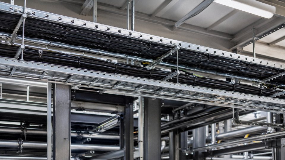
Runs get long here — several kilometers is normal in a large refinery, and LNG terminals can push that further. Field transmitters, solenoid valves, motorized ball valves, flame detectors, and emergency shutdown (ESD) actuators all need individual cabling back to the DCS or safety instrumented system (SIS). Armored construction (usually steel wire armor or aluminum wire armor) is essentially mandatory for any cable laid in cable trenches or exposed to vehicle traffic. LSZH jacket compounds are standard in most modern facilities, and flame-retardant specifications tend to follow IEC 60332-3 bunch-burn testing at minimum. The armored-and-screened combination adds cost and weight, but losing an ESD cable to mechanical damage in a hazardous area is not an acceptable trade-off.
Power Generation and Substations
Current transformers, voltage transformers, relay panels, busbar protection circuits, and circuit breaker control circuits all connect via control and protection cables. Voltage ratings here often step up — 0.6/1 kV rated cables appear regularly in substation secondary wiring. IEC 61850 process bus is gradually displacing some copper control cable volume in new greenfield substations by moving protection signals onto fiber, but the transition is slow and conventional control cable remains dominant in retrofit and brownfield projects well into the foreseeable future.
Marine and Shipbuilding
Engine rooms, bridge control consoles, cargo management systems, ballast control, and fire detection networks all run through ships on control cable. DNV GL or Lloyd’s Register approval is a procurement requirement, not optional. Halogen-free construction matters a great deal on vessels — smoke density and toxicity in an enclosed hull are life-safety issues, not just regulatory checkbox items.
Building Automation and Infrastructure
HVAC damper actuators, elevator interlock circuits, fire alarm signal circuits, access control panels — these typically run on lower core counts and modest cross-sections, often 0.75 mm² to 1.5 mm². In tunnels, hospitals, airports, and high-rise buildings, LSZH cables are mandated under current fire codes in most jurisdictions. Older buildings still have PVC-jacketed cable throughout, which is worth knowing if you are doing a phased retrofit.
Renewable Energy
Wind turbine nacelles present an unusual mechanical demand: the cable inside the tower twists continuously as the nacelle yaws. High-flex control cables with fine-stranded conductors and flexible jacket compounds are specified for this. Failure modes from using standard cable here are accelerated conductor fatigue and jacket cracking, usually showing up within a year or two rather than the expected service life. In solar farms, shielded control cables between combiner boxes and inverter control panels suppress noise from high-frequency PWM switching, which can otherwise corrupt sensor readings.
Mining and Heavy Industry
Draglines, haul trucks, and large conveyor drive control systems operate in conditions that would destroy standard industrial cables within months. Armored construction, oil-resistant jacket compounds (often TPE or PCP-based), and UV stabilization all matter. Temperature swings in open-cut mines can run from below freezing at night to well above 40 °C on exposed cable trays in summer, so jacket compound selection based on the actual site temperature range — not just a generic rating — is worth the extra step during specification.
Control cables in wind turbine towers require high-flex, fine-stranded construction to withstand continuous torsional movement during nacelle yawingTrue
Wind turbine towers experience continuous yaw rotation that twists cables; standard fixed-installation control cables are not rated for this cyclic torsional stress and fail prematurely through conductor fatigue and jacket cracking. High-flex control cables with fine-stranded conductors are specifically engineered for this duty.
How to Read a Control Cable Specification: Decoding Type Designations, Core Counts, and Datasheets
Reading a cable datasheet sounds straightforward until you’re comparing quotes from three suppliers, each using a slightly different type designation for what’s supposed to be the same cable. Getting this wrong doesn’t show up immediately — it shows up six months later when a contactor starts dropping out on a cold morning or a cable tray fill calculation is rejected during a site inspection.
Decoding a VDE-Style Type Designation
Take YSLY-JZ 7×1.5 mm² as a worked example — a common flexible control cable specified throughout European-style automation projects.
Reading left to right: the first Y indicates a PVC outer sheath. S denotes screened (present in screened variants; absent where no shielding layer exists). L specifies PVC insulation on individual conductors. The second Y confirms a PVC jacket as the outermost mechanical protection. JZ identifies the cable as a flexible, multi-core construction — the J indicating flexible stranding, Z indicating numbered cores (as opposed to colored-only identification). Then 7 is the core count, and 1.5 is the conductor cross-section in mm².
Each character is load-bearing. Swap the jacket compound code and you’ve changed the chemical resistance profile entirely. Miss the S and you’ve specified an unscreened cable into a VFD environment. In practice, many procurement teams skim the alphanumeric prefix and focus on the core count and cross-section — that’s where errors quietly accumulate.
Why Core Count Is Not Arbitrary
Counts like 7, 12, 19, and 37 aren’t random. They follow geometric packing rules — one central core surrounded by successive hexagonal layers of 6, 12, 18 cores — which produces a genuinely round cable cross-section. Deviate from these numbers and you either get a non-circular profile (problematic for glands and conduit fill) or wasted diameter. Most industrial procurement runs heavily toward 4-core, 7-core, 12-core, and 19-core configurations for exactly this reason.
The trade-off between fewer large conductors versus more small ones is real. Fewer, larger cores give you lower resistance per run and higher current capacity per conductor — useful for long runs driving high-inrush loads. More, smaller cores give you routing flexibility, easier termination in dense panels, and lower installed cable cost per circuit in multi-signal applications. A 19×0.75 mm² cable is not interchangeable with a 7×2.5 mm² cable even if the overall diameters are similar.
Datasheet Parameters That Actually Matter
Rated voltage (Uo/U, e.g., 300/500 V) sets the insulation system baseline. Conductor resistance at 20 °C (typically 12–13 Ω/km for 1.5 mm², depending on stranding class) directly feeds your voltage drop calculation. Insulation resistance should be specified in MΩ·km — values below roughly 100 MΩ·km warrant a harder look at the insulation compound. Capacitance (pF/m) matters for fast-switching signal circuits; high capacitance can degrade signal edges on longer runs. Minimum bending radius and temperature range determine installation method and routing path — a cable rated to –5 °C minimum installation temperature is genuinely problematic on an outdoor northern European site in January.
Voltage Drop in Control Circuits
Control cables rarely fail thermally. They fail because voltage drop causes a contactor to drop out or a solenoid refuses to energize. The calculation is straightforward:
V_drop = (2 × L × I × R_conductor) / 1000
where L is run length in meters, I is load current in amps, and R_conductor is resistance in Ω/km. A 75-meter run of 1.5 mm² cable (≈12.1 Ω/km) carrying 2 A gives roughly 3.6 V drop — against a 24 V DC coil, that’s meaningful margin erosion, especially if the supply voltage itself is already at the low end of tolerance.
Common Specification Mistakes
Using a power cable for control wiring is more common than it should be. Power cables use rigid Class 1 or Class 2 stranding, which fatigues quickly in a panel door application and often lacks the numbered core identification needed for maintenance. Omitting shielding anywhere near a VFD is a recurring problem — the fix after installation costs far more than the shield would have. Under-specifying jacket compound for chemical exposure (choosing standard PVC where an oil-resistant PVC-C or polyurethane jacket is needed) tends to surface during the first maintenance cycle. Bundling derating is frequently forgotten: a cable rated for 6 A in free air may be derated to 3.5–4 A when run in a tightly packed cable tray with 20 other cables.
Voltage drop, not thermal overload, is the primary failure mode in control cable runs for low-voltage automation circuitsTrue
Control cables carry low currents relative to their cross-section, so thermal limits are rarely approached. However, resistance-driven voltage drop across long runs can reduce supply voltage below the minimum pick-up voltage of contactors, solenoids, and relays, causing intermittent or complete actuation failures.
Cross-Referencing Legacy Specifications
Older projects often carry DIN or pre-harmonized VDE type codes that don’t map directly to current IEC nomenclature. Jinda’s technical support team works through this regularly — matching a legacy designation against the current construction standard, confirming the equivalent harmonized type code, and where required, issuing third-party-verified test reports for project documentation. For procurement teams dealing with plant expansions where the original cable spec is 20 years old, that cross-referencing service prevents a lot of unnecessary re-engineering.
Installation Best Practices: Routing, Segregation, Termination, and Testing
Getting the cable spec right is only half the job. A perfectly specified, fully certified control cable can still fail within a year if it’s routed carelessly, terminated sloppily, or never tested before commissioning. Most installation faults I’ve seen traced back to one of three things: tray segregation ignored during a rushed fit-out, shield grounding done wrong because nobody checked the drawing, or ferrule crimps done with the wrong tool because the correct one was left in the other building.
Cable Tray Segregation
Control cables carry low-level signals — often milliamp or millivolt range — and they pick up noise from adjacent power conductors through capacitive and inductive coupling. IEC practice calls for a minimum physical separation of 200 mm to 300 mm between control cable trays and medium-voltage or high-current power trays; the exact figure depends on the power cable’s voltage class, whether the trays are metallic and bonded, and how long the parallel run is. Separate, grounded steel trays are better than relying on distance alone. Shielded control cables reduce susceptibility, but they don’t make segregation optional — shielding attenuates noise; it doesn’t block it entirely in a long parallel run next to a 415 V motor feeder carrying 60 A of switching current.
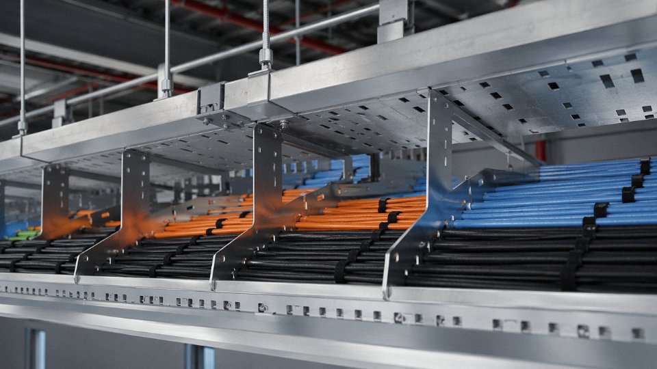
Cross the trays at 90° wherever power and control runs must intersect. It’s a small habit, but it makes a measurable difference in noise pickup on sensitive analog loops.
Bend Radius and Pulling Tension
Minimum static bending radius for unarmored control cables is typically 6× to 8× the cable’s outer diameter; armored types need 12× or more. Pulling around a cable tray corner with a tight inside radius is probably the single most common cause of invisible installation damage — the insulation cracks internally, the shield foil fractures, and nothing shows up until the first IR test six months into operation. Pulling tension should not exceed roughly 50 N/mm² of conductor cross-section. For a 7-core × 1.5 mm² cable, that works out to about 525 N maximum — easy to exceed if someone yanks a 100-meter run by hand through conduit without a pulling grip.
Shield Grounding
This is where a lot of engineers get into trouble. Grounding a cable shield at both ends is effective for high-frequency interference above roughly 1 MHz, but at power frequency it creates a circulating ground loop current that actually introduces noise into the circuit. For instrumentation and control signals below 1 MHz — the majority of plant applications — ground the shield at the panel end only, and leave the field end floating or connected through a small capacitor (typically 10 nF) if the installation standard requires it. The drain wire should run to a clean, low-impedance earth bar, not daisy-chained through a terminal block with a dozen other grounds.
Core Identification and Termination
Mark both ends of every core with ferrule markers before a single wire goes into a terminal. Use identical numbering across the cable schedule, the panel drawing, and the field junction box label. Fifteen minutes of consistent labeling at installation saves three or four hours of tracing during commissioning — that’s not an exaggeration.
Use the correct crimping tool matched to the ferrule size. An under-crimped ferrule on a 1.5 mm² core will back out of a spring-clamp terminal under vibration. Strip insulation to exactly the right depth; nicking conductor strands during stripping is subtle but serious — those damaged strands fatigue and break under repeated vibration, and the connection looks fine until it doesn’t. Torque terminal screws to the values on the terminal manufacturer’s datasheet. Most engineers skip this; most callbacks involve a high-resistance joint.
A shield grounded at both ends always improves noise rejection in control cable circuits.False
Dual-end shield grounding reduces high-frequency noise but introduces a 50/60 Hz ground loop current in the shield conductor, which can inject noise into sensitive instrumentation circuits. Single-point grounding at the panel end is standard practice for signals below 1 MHz.
Pre-Commissioning and Ongoing Maintenance Testing
Before energizing, run insulation resistance at 500 V DC for 300/500 V rated cables, or 1000 V DC for 450/750 V cables, and record the readings. Confirm continuity on every core. Verify shield continuity end-to-end. If the project spec calls for hi-pot testing, do it before terminations at the field end are landed — retrofitting after the fact causes unnecessary stress on equipment connected to the other end. Document everything as a baseline.
Periodic inspection matters more than most plants admit. Annual visual checks for jacket damage, trending IR values over time (moisture ingress shows up as a slow decline over several readings, not a sudden drop), and thermal imaging of panel terminations can catch a developing high-resistance joint before it causes a spurious trip or, worse, a localized fire. A termination running 15–20 °C above ambient in a thermal scan is worth investigating before the next scheduled shutdown, not after.
Procurement Guidance: How to Specify, Source, and Quality-Verify Control Cables for International Projects
Getting a control cable specification wrong at the purchase order stage is one of those mistakes that surfaces at the worst possible moment — during cable pulling, or worse, during commissioning when the instrument loop won’t stabilize and someone starts tracing back to the cable. A complete, unambiguous specification prevents that entirely.
Building a Specification That Leaves Nothing to Interpretation
A purchase order for control cable should include, at minimum: the type designation or standard reference (e.g., KVVP2, YSLY-JZ, or IEC 60227/IEC 60502 as applicable), rated voltage, number of cores and cross-section stated together (e.g., 7 × 1.5 mm²), conductor material and class (plain annealed copper, Class 2 or Class 5 for flexible), insulation and jacket compound (PVC, XLPE, LSZH — and the specific grade where it matters), shielding type if required (overall foil, braided, or both, with coverage percentage specified), armoring type if applicable, core identification method (color code to IEC 60446 or numeric), drum length, and any project-specific approval — DNV GL for marine, ATEX-rated jacket compound for Zone 2, UL listing for North American installations. If your project engineer says “just get the standard cable,” ask which standard. That single question prevents a re-specification three months in.
What Supplier Quality Actually Looks Like
ISO 9001 certification matters, but it’s a floor, not a ceiling. What separates a reliable control cable manufacturer from a compliant-on-paper one is the test infrastructure behind the certificate. Look for an in-house cable test laboratory capable of conductor resistance measurement per IEC 60228, spark testing at appropriate voltage on every meter of insulated core (typically 4 kV a.c. or equivalent d.c. for 0.6/1 kV-class insulation), and capacitance measurement on shielded types — because a shielded cable with excessive capacitance will degrade signal integrity in analog instrumentation loops even if it passes every visual inspection.
Third-party type test reports from accredited bodies — CESI, KEMA, TÜV, SGS, Intertek — carry real weight. Ask for them. Ask also for raw material traceability: copper rod certificates showing conductivity and purity, and compound certificates for PVC or XLPE batches tied to the specific production lot on your order. A manufacturer that can’t produce these documents at audit is telling you something important.
Factory Audit Checkpoints Worth Verifying
On a factory visit or third-party audit, the areas that reveal the most are: extrusion line temperature control logs (compound degradation from overheating shows up in long-term insulation resistance, not in a day-one spark test), conductor resistance verification per finished reel against IEC 60228 tolerances, spark test continuity records, and drum labeling accuracy — length measurement errors of 5–10% are not unheard of with some suppliers, and that discrepancy hits you at installation.
Lead Times, Drum Lengths, and Freight Logic
Standard catalog types from a held stock range ship within days. Custom configurations — unusual core counts, special compound, specific armoring — typically need 4 to 8 weeks of production lead time, depending on batch size and compound availability. Drums run roughly 500 m to 2,000 m depending on cable diameter; a 19 × 2.5 mm² armored drum can weigh 600–900 kg, which immediately shifts the freight conversation from air to sea. For urgent partial requirements, air freight on a smaller reel is sometimes the only option. Build this into project contingency budgets.
Jinda exports control and specialty cables to customers across the Middle East, Southeast Asia, Africa, Europe, and the Americas, supported by country-of-origin certificates, material test reports, and third-party inspection coordination.True
Jinda operates five production bases in Shandong province covering 470,000 m² and has supplied international projects across more than 50 countries since its founding in 1987.
The Total Cost Calculation Most Buyers Get Wrong
A cable priced 12–18% lower per meter looks attractive until it fails insulation resistance acceptance tests on-site — and re-pulling a 300-meter run through a congested cable tray in an operating plant costs multiples of the original material saving, before you factor in schedule delay. Specify conductor resistance compliance, minimum insulation resistance values (typically ≥ 100 MΩ·km for new PVC-insulated control cable, though this varies with core count and temperature), and acceptance test procedures directly in the purchase order. That language protects project value and gives you contractual standing if material doesn’t perform.
Jinda’s manufacturing scale — five bases, over 1,000 employees, a product range spanning control, power, instrumentation, fire-resistant, and specialty cables — means standard types are available without the lead time risk of a single-line producer, and project-specific requirements can be handled without subcontracting core production processes.
Frequently Asked Questions About Control Cables
Can I use a control cable instead of a power cable to supply a small motor?
Don’t do it. Control cables are designed around switching and signal duties — their conductors are sized to carry milliamps to a few amps at most, and their insulation systems are validated for that thermal regime. Put a 0.75 mm² or even a 2.5 mm² control cable core on a motor circuit running continuous load current and you’re asking for thermal overload, insulation softening, and eventually a fire or a nuisance trip at the worst possible moment. Even a “small” 0.37 kW single-phase motor can draw 2–3 A continuously at full load, which sounds modest until you account for locked-rotor inrush of 5–7× that figure.
The right tool is a properly rated power cable sized to IEC 60364-5-52 (or your applicable national annex), accounting for ambient temperature, grouping, and installation method. No shortcut here.
What is the difference between a control cable and an instrumentation cable?
They overlap in voltage class and general appearance, which is why they get confused on procurement lists. A control cable is built for discrete switching — running a PLC output to a contactor coil, carrying a 24 V DC on/off signal, transmitting a low-power analog command. The priority is reliable current-carrying at up to 450/750 V and mechanical robustness across a cable tray full of other conductors.
Instrumentation cable is a different design philosophy entirely. The signal levels are smaller — 4–20 mA loops, 0–10 V analog, thermocouple millivolt signals in the single digits — and accuracy is everything. Individual pairs or triads with their own drain wires and foil shields, low capacitance to prevent signal distortion across long runs, high insulation resistance to keep leakage currents from corrupting a precision measurement. Swap them, and you’ll get unexplained drift or noise on a thermocouple input that will send a maintenance tech chasing ghosts for days.
How many cores do I need?
Count every discrete signal, every common return, every interlock, and then add 20% spare capacity on top. This is standard industry practice, not over-engineering — field devices get added, interlocks get revised, and a cable already installed in a conduit buried under a concrete floor cannot be replaced cheaply. A device needing 6 active cores should drive you toward a 7-core or 8-core cable at minimum.
For larger junction runs, 12-core and 19-core cables are almost always more economical than running multiple 4-core or 7-core cables in parallel — fewer termination entries, less tray fill, and a single drum to manage on site.

Does a shielded control cable eliminate the need for tray segregation from power cables?
No. Shielding reduces capacitive (electric field) coupling, and a correctly terminated, single-point-grounded shield also reduces inductive coupling to a useful degree. But IEC 61000 and IEEE 518 still require physical separation — typically 150–300 mm depending on voltage class and whether trunking or metallic trays are involved. A parallel run of 400 V power cables carrying several hundred amps will still induce interference into an adjacent control cable bundle regardless of shielding if the separation is inadequate. Shielding and segregation are complementary, not substitutes.
What is the maximum length for a control cable run before signal integrity becomes a problem?
It depends heavily on the signal type, which is the honest answer. For 24 V DC discrete control, voltage drop drives the limit — a 1.5 mm² core can typically manage 200 to 400 m before the receiving contactor drops below its minimum pick-up voltage, but the actual figure depends on conductor resistance, loop current, and the relay’s voltage tolerance. For 4–20 mA analog loops, the constraint is total loop resistance; if the transmitter has a 600 Ω maximum load specification and you’re at 580 Ω already, one extra spur will push it out of range. For Modbus RTU or PROFIBUS over control cable, capacitance per meter and characteristic impedance determine segment length limits that the fieldbus standard specifies precisely.
Sketch the loop, calculate the parameters, check them against the device datasheet. Guessing on cable runs is how you end up troubleshooting at 2 a.m.
Are LSZH control cables always required in offshore and marine installations?
Not universally, but the trend is firmly in that direction. DNV, Lloyd’s Register, Bureau Veritas, and ABS all mandate low-smoke, halogen-free cables in accommodation spaces, escape routes, stairwells, and enclosed machinery spaces — areas where toxic combustion gases and reduced visibility would impede evacuation. Conventional PVC-jacketed cable may still be accepted in certain open-deck external locations or non-critical utility runs, depending on the classification society’s rules and the flag state’s additional requirements.
The practical rule: pull the project’s approved cable schedule and the applicable class notation before you specify anything. Getting this wrong means a rejected material list and a delay in getting cable to the vessel — not a conversation anyone wants with a project manager mid-outfitting.
How does Jinda ensure consistent quality across large-volume export orders?
Jinda operates an ISO 9001-certified quality management system with in-process spark testing on every insulated core and 100% electrical testing on completed cables per IEC standards, with full batch traceability from copper rod to finished drum.True
These are documented manufacturing practices at Jinda's production facilities, verifiable through factory audits and quality records supplied with shipment documentation.
For export projects where the buyer needs independent assurance, Jinda supports third-party inspection by SGS, Bureau Veritas, or any customer-nominated inspection body at the factory prior to shipment. Drums are labeled with full traceability data — production batch, test records, drum length — so an EPC or end-user procurement team can reconcile what arrives on site against what was tested in the factory. With five production bases and over 470,000 m² of manufacturing space, volume commitments that would strain a smaller mill are within normal operating range.