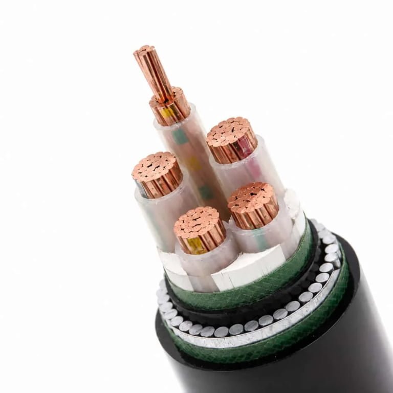
Specify the wrong voltage rating on a low voltage cable and you’re not just looking at a failed inspection — you’re looking at insulation breakdown under load, nuisance tripping that your maintenance team will chase for weeks before finding the real cause, and in worst cases, a fire event that voids your insurance and shuts the line. Procurement managers ordering by price alone, and engineers who copy cable specs from an old drawing without checking the new system voltage, both make this mistake more often than anyone likes to admit.
Low voltage cables handle AC systems up to 1,000 V and DC systems up to 1,500 V per IEC 60038 and NEC standards. Within that range, common ratings are 300/500 V, 450/750 V, and 0.6/1 kV — where the first figure is conductor-to-ground voltage and the second is conductor-to-conductor. Picking the right rating depends on your system voltage, installation method, and whether you’re running AC or DC.
What gets engineers into trouble isn’t usually the headline voltage limit — it’s the gap between what a cable is rated to withstand and what it can actually carry continuously without degrading, which pulls in conductor cross-section, current density, ambient temperature, and how many cables are bundled together. Those factors interact in ways that aren’t obvious from a spec sheet alone.
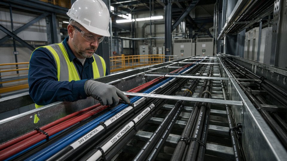
Voltage Rating vs. Current Rating: The Two Limits Every Engineer Must Separate
These two parameters get conflated constantly — on job sites, in spec sheets, even in some purchasing conversations. They are not the same thing, they are not interchangeable, and they are governed by completely different physics. Getting this wrong is one of the more reliable paths to a premature cable failure.
Voltage Rating: An Insulation Problem
A cable’s voltage rating is determined entirely by the dielectric strength of its insulation — the ability of that material to resist electric field breakdown without conducting current through it. XLPE runs roughly 20–30 kV/mm of dielectric strength; PVC sits lower, typically 15–20 kV/mm depending on compound grade and temperature. The insulation thickness is then specified to maintain an adequate margin above the system’s continuous operating voltage and its transient peaks.
A 0.6/1 kV cable — the first figure being conductor-to-ground, the second conductor-to-conductor — typically carries 0.8–1.0 mm of XLPE or PVC wall thickness, depending on conductor cross-section and the applicable standard (IEC 60502-1 being the usual reference). A 300/500 V cable might have only 0.5–0.6 mm. That difference looks trivial until you run the IEC 60502-1 dielectric withstand test: the formula is 2U₀ + 2,000 V applied for a short duration, where U₀ is the rated conductor-to-ground voltage. For a 0.6/1 kV cable that puts the test voltage at 3,200 V. For a 300/500 V cable the same formula gives 2,600 V. Those aren’t large margins — they’re the reason you can’t substitute downward on voltage class without genuinely reviewing the installation conditions.
Impulse Withstand Matters More Than Steady-State Voltage
The rated continuous voltage is not the worst thing the insulation will ever see. Switching transients in industrial panels — particularly when contactors or VFDs interrupt inductive loads — can produce spikes well above system voltage. Lightning surges are worse. For 1 kV-class cables, the impulse withstand voltage (Ui, sometimes called rated impulse voltage) typically falls in the 4–6 kV range. Cables rated at 0.6/1 kV are routinely tested to 4 kV impulse per IEC 60502-1. Cheaper 300/500 V flex cables are not designed for that environment. Running one in a panel with any significant switching load is asking for insulation puncture — not immediately, but through progressive degradation over months or years.
Current Rating: A Thermal Problem
Here’s the part that catches people. A 1.5 mm² H07V-K flexible wire rated at 450/750 V will carry roughly 15–17 A continuously in free air, depending on ambient temperature and installation method — that range shifts down toward 13 A if it’s bunched with other loaded cables or clipped to a surface. Exceed that current limit by 20–30% for any sustained period and the PVC insulation begins softening. Exceed it by 50% and you’re looking at thermal degradation that can progress to shorts within hours in a warm enclosure. The dielectric strength of the insulation is essentially untouched throughout this whole process. The voltage rating is fine. The cable is still failing.
Undersizing conductor cross-section is more dangerous in practice than running a low-voltage cable slightly below its rated voltage class.True
Thermal failure from excessive current density is the dominant failure mode in low-voltage installations. The insulation dielectric margin is typically 2–3× the operating voltage, while thermal margins are much tighter and depend on installation method, ambient temperature, and bundling — factors that frequently push real-world conditions close to the limit.
Resistive heating scales with I²R, so doubling the current quadruples the heat generated in the conductor. The insulation temperature rating — 70 °C for standard PVC, 90 °C for XLPE — sets the hard ceiling on continuous current, not voltage. In practice, an installation that’s thermally marginal will fail within a few years of commissioning; one that’s running at 80% of rated voltage in a 1 kV-class cable will likely outlast the building.
Side-by-Side Reference
| Rated Voltage Class | Typical Insulation Thickness (PVC) | Typical Insulation Thickness (XLPE) | IEC Dielectric Test Voltage (2U₀ + 2,000 V) | Impulse Withstand (Ui) |
|---|---|---|---|---|
| 300/500 V | 0.5–0.6 mm | 0.4–0.5 mm | 2,600 V | ~2.5 kV |
| 450/750 V | 0.6–0.7 mm | 0.5–0.6 mm | 2,900 V | ~2.5–4 kV |
| 0.6/1 kV | 0.8–1.0 mm | 0.7–0.9 mm | 3,200 V | 4–6 kV |
Actual thickness varies by conductor size and standard — treat these as orientation values, not spec-sheet substitutes. Always verify against the specific cable standard (IEC 60502-1, HD 603, or equivalent) for the product you’re procuring.
The practical takeaway is simple: when reviewing a cable’s suitability for a circuit, check the current-carrying capacity first against your calculated load and your installation conditions. Voltage class is usually not the limiting constraint in a properly specified low-voltage system. Thermal headroom almost always is.
How Insulation Material Controls the Voltage Ceiling: PVC, XLPE, and Rubber Compared
The voltage rating stamped on a cable isn’t an arbitrary number picked by the marketing department. It’s determined almost entirely by the insulation material — specifically its dielectric strength, how that strength degrades with heat and age, and how thick a wall the manufacturer can practically extrude around the conductor. Choose the wrong insulation for your voltage environment and you’re not just looking at a code violation; you’re looking at progressive insulation breakdown that can run quietly for months before it fails catastrophically.
Dielectric Strength: What the Numbers Actually Mean on the Factory Floor
Dielectric strength is measured in kV/mm — how many kilovolts the material can withstand per millimeter of thickness before it breaks down. PVC sits in the 15–20 kV/mm range depending on formulation, plasticizer content, and temperature. XLPE and EPR both run roughly 20–25 kV/mm. Silicone rubber is back down around 15–20 kV/mm, similar to PVC, though it earns its place through thermal performance rather than raw dielectric numbers.
What this means practically: a standard 0.6/1 kV XLPE-insulated cable might have an insulation wall of 0.7–1.0 mm for smaller conductor sizes. Run the arithmetic — even at the low end of XLPE’s dielectric range, that’s 14–25 kV of withstand capability against a 1 kV rated system. The safety margin is substantial, which is exactly the point. Insulation doesn’t just handle the rated voltage; it has to survive voltage spikes, switching transients, and partial discharge events without accumulating damage over a 20–30 year service life.

PVC’s Thermal Penalty and Why It Matters Under Load
PVC is workable, cheap, and widely available — it’s still the dominant insulation for general wiring in buildings across most of the world. The problem is its thermal ceiling. Standard PVC-insulated cables are rated for 70°C conductor temperature under continuous operation. Dielectric strength in PVC drops noticeably as temperature climbs; at or near 70°C, you’ve already consumed a meaningful slice of that margin. Push the load hard in a warm cable tray during a summer peak and you’re running the insulation hotter than the rated conditions while simultaneously reducing the dielectric strength that protects against voltage stress.
This is why you’ll often see PVC-insulated cable specified conservatively in industrial environments — engineers derate current capacity to keep conductor temperature well below 70°C, partly for thermal reasons and partly to preserve insulation life.
Moisture and UV exposure make things worse. Outdoor or direct-burial PVC installations absorb water over time, particularly at joints and terminations. Plasticizers leach out. The insulation becomes brittle and its effective dielectric strength degrades — not dramatically in year one, but meaningfully by year eight or ten. This is the kind of failure mode that doesn’t show up in acceptance testing; it shows up as a ground fault on a wet February morning, years after installation.
PVC insulation loses dielectric strength progressively when exposed to moisture and elevated temperature over multi-year service periodsTrue
Plasticizer migration and thermal oxidation degrade PVC's polymer chain structure over time, reducing its ability to resist electric stress. This is well-documented in IEC aging studies and reflected in derating guidelines for long-service-life installations.
Why XLPE Dominates Industrial and Infrastructure Cable Specifications
XLPE’s cross-linked molecular structure changes the game. The cross-linking process creates a three-dimensional polymer network that resists thermal softening, which is why XLPE is rated to 90°C continuous conductor temperature versus PVC’s 70°C — that’s not a small difference when you’re sizing cables in a packed conduit bank. Under short-circuit conditions, XLPE can withstand conductor temperatures up to roughly 250°C without losing structural integrity, where PVC would deform and potentially allow conductors to touch.
For 0.6/1 kV applications — the workhorse rating for industrial distribution, infrastructure cabling, and utility connections — XLPE is the default insulation in most serious specifications globally. Its higher dielectric strength means equivalent protection at thinner walls, and its thermal stability means voltage-withstand capability doesn’t erode the same way PVC’s does under sustained load.
EPR (ethylene propylene rubber) offers comparable dielectric strength to XLPE and considerably better flexibility in cold temperatures. It’s common in mining, shipboard, and portable cable applications where mechanical flexing matters and PVC would crack. The trade-off is cost — EPR compounds run noticeably higher than XLPE, sometimes 30–50% more depending on formulation and market conditions, so it rarely displaces XLPE in fixed-installation infrastructure work.
LSZH / HFFR: Not Just About Smoke, But Voltage Performance Too
Low-smoke zero-halogen (LSZH, also called HFFR) insulation was developed primarily for enclosed spaces — tunnels, data centers, transit systems — where PVC’s combustion byproducts would be lethal in a fire event. But the voltage performance question is legitimate, because early LSZH formulations had noticeably lower dielectric strength than PVC and required thicker insulation walls to compensate.
Modern LSZH compounds have closed that gap significantly. Current formulations from reputable manufacturers can achieve dielectric ratings equivalent to standard PVC at similar wall thicknesses, which means a properly specified LSZH cable at 300/500 V or 0.6/1 kV doesn’t involve any voltage-handling compromise compared to PVC. The difference shows up in cost (LSZH materials run higher) and in installation feel — LSZH jackets tend to be stiffer and can be more challenging to pull through conduit on large conductor sizes.
For projects with defined regulatory requirements around fire performance — IEC 60332 series, EN 50575 Euroclass ratings, or specific transit authority standards — LSZH is often mandatory regardless of cost. The voltage capability is there; it’s the compliance paperwork and material cost that drive the conversation.
Matching Insulation to Your Operating Environment
A 0.6/1 kV cable is a 0.6/1 kV cable regardless of insulation — but “can it handle the voltage” is a much longer question than the nameplate suggests. What the cable experiences over its service life depends heavily on whether the insulation can maintain its dielectric properties under the actual operating temperature, moisture exposure, UV, and mechanical conditions of the installation.
Jinda manufactures low voltage cables across PVC, XLPE, and LSZH insulation systems precisely because no single material suits every environment. A direct-burial distribution run in a high-ambient-temperature region calls for a different insulation specification than a flexible connection in a cold-climate mining application or a data-center raised-floor run where fire code drives the material choice. The voltage rating sets the ceiling; the insulation material determines whether the cable actually holds that ceiling reliably through a full service life.
Conductor Size, Cross-Section, and the Voltage Drop Equation in Real Installations
Once you’ve confirmed that the cable’s insulation can handle the system voltage — which the previous sections covered — the next problem is whether the conductor itself can deliver that voltage to the load end without bleeding off too much of it as resistive heat. This is the voltage drop problem, and in low voltage systems it bites far more often than insulation failure does.
The governing equation for a single-phase circuit is:
V_drop = I × R × L × 2
For three-phase:
V_drop = I × R × L × √3
where R is the conductor’s AC resistance in Ω/km at operating temperature, L is the one-way cable run in km, and I is the load current in amperes. The factor of 2 in single-phase accounts for both the live and neutral conductors carrying current. Simple enough on paper. In practice, engineers either forget the ×2, ignore temperature correction, or — most commonly — just size by ampacity and hope the voltage holds up. It usually doesn’t on runs beyond 40–50 m at higher currents.
A Worked Example Worth Keeping Handy
Take a 32 A single-phase load at 230 V, sitting 80 m from the distribution board — a fairly typical motor feeder or workshop socket circuit. The cable is 6 mm² copper, which has a resistance of roughly 3.08 Ω/km at 20°C per IEC 60228.
V_drop = 32 × 3.08 × 0.08 × 2 = 15.77 V
That’s 6.9% of 230 V. The IEC and BS 7671 limit for final circuits is 4%, meaning 9.2 V maximum on a 230 V system. This cable fails the voltage drop check by a significant margin, even if 6 mm² is perfectly adequate for 32 A thermally. Moving to 10 mm² (1.83 Ω/km) drops the loss to 9.37 V — still marginally over. 16 mm² (1.15 Ω/km) gives 5.9 V, which is within spec. So the installed cable ends up one or two sizes larger than the ampacity tables would suggest. That’s the norm, not the exception, on anything beyond a short home run.
Resistance Per Kilometer Reference Table (Copper, 20°C, IEC 60228)
| Cross-Section (mm²) | Max. Resistance (Ω/km) |
|---|---|
| 1.5 | 12.10 |
| 2.5 | 7.41 |
| 4 | 4.61 |
| 6 | 3.08 |
| 10 | 1.83 |
| 16 | 1.15 |
| 25 | 0.727 |
| 35 | 0.524 |
| 50 | 0.387 |
| 70 | 0.268 |
| 95 | 0.193 |
| 120 | 0.153 |
| 150 | 0.124 |
| 185 | 0.0991 |
| 240 | 0.0754 |
Values are for plain copper, round stranded conductors. Real installed resistance will be higher at operating temperature — roughly 0.4% per °C above 20°C, so a cable running at 70°C carries about 20% more resistance than the table shows. For precise sizing, always apply the temperature correction.
Aluminum: Bigger, Cheaper, Heavier
Aluminum conductors need a cross-section roughly 1.6× larger than copper to match the same resistance — so where you’d use 95 mm² copper, you’re looking at 150 mm² aluminum. The trade-off is real: aluminum is typically 40–60% cheaper by weight at market prices (depending heavily on LME spot and alloying grade), but the larger cross-section means bigger terminations, heavier cleats, and potentially a larger conduit or tray. On long rural distribution runs — 500 m or more — aluminum almost always wins on total installed cost. On short industrial drops where labor and termination hardware dominate, the saving narrows considerably.
The Cumulative Drop Problem on Long Feeders
A single 80 m run is manageable. A rural low voltage distribution network feeding several loads 300–600 m from a substation is a different situation entirely. Voltage drop is cumulative — each segment in series adds to the deficit at the furthest load. It’s not unusual to find the ampacity-correct cable producing 8–12% voltage drop by the time you reach the end of the run, causing motors to run hot, variable-speed drives to trip on undervoltage, and lighting to flicker noticeably. The fix is always the same: oversize the feeder conductors relative to what pure current-carrying capacity requires, or split the network with an additional supply point.
This is where the concept of economic cross-section becomes genuinely useful rather than academic. The logic is straightforward: a larger conductor costs more upfront but wastes less energy in resistive losses over its service life, which typically runs 25–40 years for buried infrastructure cable. For a 300 m, 150 A three-phase feeder running at 70% load factor, stepping from 95 mm² to 150 mm² copper might add $3,000–8,000 to material cost (depending on copper pricing and project scale) but recover that difference in energy savings within 4–8 years at typical industrial electricity tariffs. Beyond that breakeven, every year is pure savings.
Sizing low voltage cables purely by ampacity without checking voltage drop is compliant with thermal limits but can still result in underperforming or non-compliant installations.True
IEC 60364 and BS 7671 impose both a current-carrying capacity requirement and a separate voltage drop limit. A cable that passes the ampacity check can still fail the voltage drop check, especially on longer runs at higher currents. Both criteria must be satisfied independently.
The practical takeaway: run the voltage drop calculation before finalizing any cable cross-section, not as an afterthought. On runs under 20–25 m at modest currents, ampacity will usually govern. Beyond that, voltage drop often does — and ignoring it is how you end up pulling cable twice.
Temperature, Installation Method, and Derating Factors That Reduce Safe Voltage-Handling Capacity
A cable’s nameplate rating is not a guaranteed operating limit — it’s a reference condition. Both IEC 60364-5-52 and NEC 310 publish ampacity tables at a baseline ambient of 30°C, with the conductor temperature assumed to be at its rated ceiling (70°C for standard PVC, 90°C for XLPE). The moment your actual installation conditions diverge from those reference conditions — and they almost always do — you are required to apply correction factors that reduce the cable’s safe carrying capacity below that printed figure.
Derating, in plain terms, is the mandatory reduction of a cable’s rated ampacity to account for the extra heat that real-world conditions trap around the conductor. Voltage handling is not directly derated the same way current is, but the connection is tight: once a conductor runs hotter than its insulation was designed for, the insulation degrades, and a cable that has been thermally overstressed for months or years will eventually fail at voltages it should handle comfortably.
Ambient Temperature Correction
For PVC-insulated cables with a 70°C conductor temperature rating, the IEC correction factors shift meaningfully across the range of climates you actually encounter in the field:
| Ambient Temperature (°C) | Correction Factor |
|---|---|
| 10 | 1.22 |
| 20 | 1.12 |
| 25 | 1.06 |
| 30 | 1.00 (reference) |
| 35 | 0.94 |
| 40 | 0.87 |
| 45 | 0.79 |
| 50 | 0.71 |
| 60 | 0.58 |
A cable derated to 0.58 of its rated ampacity — which is what you face running PVC wire in a 60°C ambient, say inside an uncooled steel enclosure in a Gulf region summer — is carrying barely half the current it looks rated for on paper. Ignore that and the insulation cooks. Slowly, invisibly, until it doesn’t.
Cable Grouping and Mutual Heating
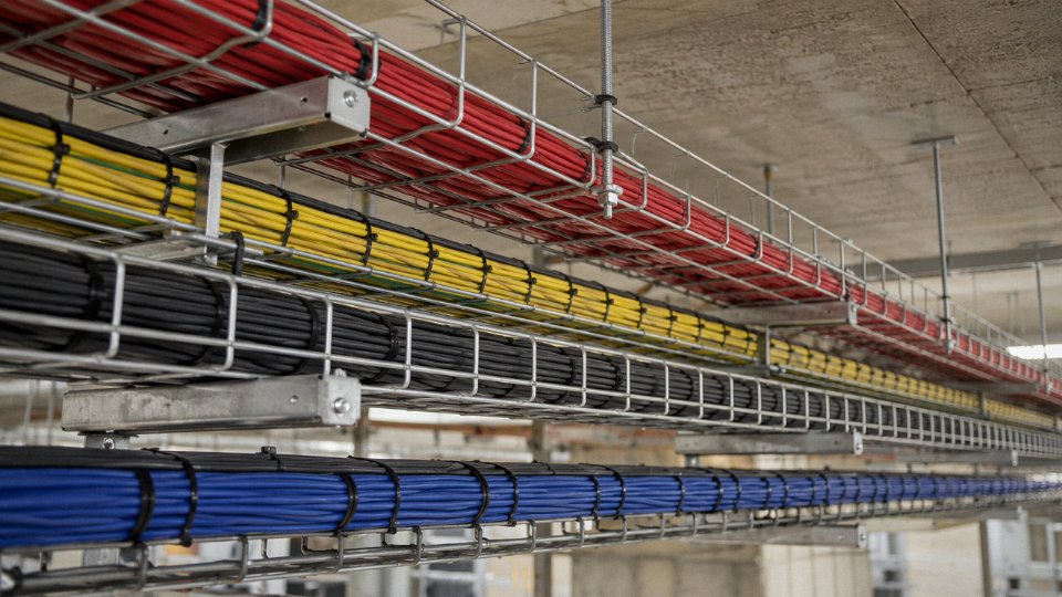
Grouping multiplies the problem. When six single-core cables are bundled touching in a tray or conduit, each conductor’s waste heat has nowhere to go — the adjacent cables act as insulation. IEC 60364-5-52 Table B.52.17 puts the grouping factor for six circuits touching at roughly 0.57, meaning each cable in that bundle should be sized as though it can only carry 57% of its standalone ampacity. In practice, on plant floors with dense cable trays, engineers sometimes stack cables in multiple layers without accounting for this, which is one of the more common causes of nuisance tripping and premature insulation failure I’ve seen.
Installation Method and Thermal Resistance
The installation method itself controls how well heat can escape. Ranked roughly from best to worst heat dissipation: free air with airflow > clipped directly to a masonry wall > open perforated cable tray > enclosed conduit in air > direct burial in moist soil > direct burial in dry soil > conduit buried in dry soil.
That last one surprises people. Dry soil has a thermal resistivity that can reach 2.5–3.0 K·m/W depending on composition and moisture content — worse than moist soil at around 1.0 K·m/W. A cable that runs fine in free air may need to be one or two cross-section sizes larger when buried in sandy, dry ground in an arid climate. Burial depth matters too; shallower burial in the 0.5 m range typically dissipates heat better than the 1.0–1.2 m depths used in some utility work.
The Arrhenius Aging Effect
This is where derating connects directly to long-term voltage-handling capacity. Polymer insulation ages thermally according to the Arrhenius model: every 10°C sustained above the rated conductor temperature roughly halves the insulation’s expected service life.
Operating a PVC cable at 80°C conductor temperature instead of its rated 70°C will approximately halve its insulation service life over time.True
This follows the Arrhenius thermal aging model, which is the basis for IEC 60216 and is widely applied in cable insulation life prediction. A 10°C increase above rated temperature is the standard half-life interval used in the industry.
A cable that reaches end-of-insulation-life prematurely will show reduced dielectric strength — meaning it becomes unreliable at the very voltage it was rated to handle. That’s how you get intermittent ground faults on a 0.6/1 kV system from a cable that was never technically overvoltaged.
VFDs, Harmonics, and the Often-Missed Factor
Variable frequency drives and UPS systems inject harmonic currents — particularly the 3rd and 5th harmonics — that increase the RMS current the cable actually carries beyond what the fundamental load calculation suggests. In three-phase systems with high third-harmonic content, the neutral conductor can carry current exceeding the phase conductors. If your project includes VFD-driven motors or switch-mode power supplies, you need to factor this in before finalizing cable sizing.
Practical Derating Checklist for Project Engineers
Run through this before finalizing any cable selection:
- Ambient temperature zone — peak sustained ambient, not the comfortable average
- Number of cables grouped — count circuits, not just conductors; apply the correct IEC or NEC grouping factor
- Installation method — conduit, tray, direct burial, free air; each has its own base ampacity column
- Soil thermal resistivity — for buried cables, get a measured value or use a conservative 2.5 K·m/W if data is unavailable
- Harmonic load content — confirm whether VFDs, rectifiers, or UPS systems are on the circuit
- Combined factors — multiply all applicable correction factors together; the cumulative result is sometimes surprisingly low
Running all five correction factors simultaneously on a dense industrial installation is not unusual, and the combined derating can easily push you to 40–50% of the cable’s reference ampacity. Size for that from the start.
International Standards That Define Low Voltage Wire Voltage Ratings: IEC, NEC, BS, and GB Compared
If you are sourcing cables across borders — say, a Chinese-manufactured product going into a UK substation project or a North American industrial facility — the single fastest way to create an expensive acceptance problem is to assume one standard’s voltage rating maps cleanly onto another’s. They mostly align, but the notation, the test sequences, and the certification marks differ enough to generate real project delays.
IEC: The Baseline Most of the World Uses
Three IEC documents do the heavy lifting for low voltage cable ratings. IEC 60502-1 covers power cables with extruded insulation rated at 0.6/1 kV — the 1 kV class that sits at the top of the low voltage range. The “0.6/1 kV” notation is IEC’s Uo/U system: 0.6 kV conductor-to-earth, 1 kV conductor-to-conductor. Part 1 of that standard specifies construction, dimensional tolerances, and the test sequence a manufacturer must pass before the cable ships. For flexible and light-duty wiring, IEC 60227 governs PVC-insulated cables up to 450/750 V, and IEC 60245 covers the rubber-insulated equivalents used in more demanding thermal or mechanical environments. These two standards define the lower voltage tiers that show up in most building wiring and machine tool applications.
The voltage type tests under IEC 60502-1 are not trivial. An AC withstand test typically applies somewhere around 3.5 kV for several minutes on a finished 0.6/1 kV cable — exact figures depend on insulation thickness and cable construction. Insulation resistance is measured at 20°C and at elevated temperature, and the partial discharge test (usually performed at 1.73 × Uo, so roughly 1.04 kV for a 0.6/1 kV rated cable) checks for internal voids that would cause premature insulation breakdown in service. Fail the partial discharge test and the cable is not 1 kV class, regardless of what the jacket print says.
NEC and UL: North America’s Parallel System
The US system uses different class breakpoints. NEC Article 310 organizes conductors into 300 V, 600 V, and 1,000 V categories — so a 600 V-rated THHN conductor under UL 83 is roughly comparable to an IEC 450/750 V cable, but the test methods and construction details are not identical. UL 44 covers thermoset-insulated wire. In practice, an IEC-compliant cable without UL listing cannot be installed in a UL-inspected facility in the US, full stop. Third-party testing to UL standards adds cost and lead time — typically several weeks for a new product, longer if the factory is not already in UL’s program.
BS and the HAR Mark in Europe
UK practice layers BS 7671 (the IET Wiring Regulations) over cable construction standards like BS 6004 (PVC-insulated, up to 300/500 V) and BS 6346 (PVC-armored power cables). Post-harmonization, British cable standards aligned closely with IEC, and cables carrying the HAR mark — indicating compliance with CENELEC harmonized standards — are accepted across EU member states. This matters for procurement: a HAR-marked cable produced to HD 21 or HD 22 series norms can be specified in Germany, France, and Poland without re-testing. The HAR mark is a certification administered through national bodies, not self-declared.
GB Standards and Dual Certification
China’s GB/T 12706 series mirrors IEC 60502 closely enough that the test requirements and rated voltage classes are essentially equivalent. GB/T 5023 aligns with IEC 60227. Jinda produces cables to both GB and IEC standards from the same production lines — meaning a project engineer can receive cables with Chinese CCC certification for domestic grid use and IEC-compliant product for export, without the factory running two separate processes. The practical benefit for procurement managers is simpler vendor qualification: one audit, one production base, documentation packages for multiple destination markets.
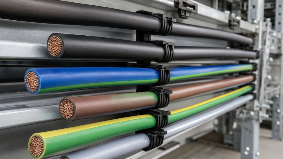
Cables marked 0.6/1 kV under IEC 60502-1 and cables marked 600 V under UL 83 are not interchangeable without review, because the test protocols and construction requirements differ.True
IEC 60502-1 and UL 83 use different withstand test voltages, different insulation thickness calculations, and different conductor resistance limits. A cable passing one standard's tests is not automatically compliant with the other, and mixing them without engineering sign-off creates both safety and insurance liability exposure.
What Documentation to Demand
When importing low voltage cables, ask for the full type test report from an accredited third-party lab — not a factory self-test certificate. For EU destination projects, a Declaration of Conformity and the HAR or CE mark where applicable. For North America, UL listing documentation with the specific file number, verifiable on UL’s public database. KEMA (now DEKRA) and SABS approval matter for projects in the Netherlands and South Africa respectively. A reputable manufacturer will have these on file and can provide them within a few days; if the response is slow or the documents look templated without a real lab report behind them, that is a signal worth taking seriously.
Low Voltage Cable Selection Guide: Matching Wire Voltage Capacity to Real-World Applications
Knowing the theoretical voltage ceiling of a cable class is one thing. Picking the right cable for a specific job — with its particular fault current exposure, installation environment, and service life expectation — is where the real engineering happens. These five application categories cover the vast majority of low voltage projects engineers encounter.
Residential and Light Commercial Wiring (230/400 V AC)
Most household and small commercial circuits run at 230 V phase-to-neutral or 400 V phase-to-phase. A 300/500 V or 450/750 V rated cable covers that comfortably, with the insulation rated well above the operating voltage. Flexible cords like H05VV-F (300/500 V) handle pendant lighting, appliances, and office equipment. Fixed wiring uses NYM or NYY in many European-influenced markets; THHN rated at 600 V dominates North American and export projects following NEC practice. In practice, the selection criteria here are less about voltage headroom — you have plenty — and more about flame spread class, smoke emission, and whether the installation is concealed in a wall or run in open conduit. Upsizing to 450/750 V insulation in a residential job adds modest cost but buys extra margin if the cable ever sees momentary overvoltage during a switching transient.
Industrial Power Distribution (Up to 1 kV)
Step onto a plant floor feeding 400 V motor control centers and the calculus changes quickly. Fault currents are higher, the cable may be clamped against hot surfaces, and mechanical abuse — forklift scrapes, repeated flexing at cable entry glands — is routine. This is the territory for 0.6/1 kV rated cables: NYY for general duct and tray runs, N2XY (XLPE insulated) where thermal performance matters, and armored variants — SWA (steel wire armor) or AWA (aluminum wire armor) — wherever the cable is exposed to physical impact or rodent risk. Motor feeder cables should always be specified at 0.6/1 kV even when the motor nameplate says 400 V; the extra insulation grade handles voltage spikes from VFD switching without progressive insulation degradation over a 20-year service life.
Solar PV DC Wiring
This one trips up procurement teams more than almost any other application. A utility-scale PV string can sit at 1,000 V DC — right at the IEC DC low voltage ceiling — and standard AC cables are absolutely not suitable. DC arc behavior is fundamentally different: unlike AC arcs that self-extinguish at current zero crossings, a DC arc sustains itself. Cables for PV strings need insulation tested specifically for DC voltage stress, UV and ozone resistance for rooftop or open-rack exposure, and compliance with IEC 62930 or EN 50618. Substituting a cheaper NYY or THHN cable because “the voltage numbers look the same” is an operational warning worth repeating — it has caused fires in ground-mount installations.
Standard AC low voltage cables rated 0.6/1 kV can be used for 1,000 V DC solar PV string wiring.False
AC cable ratings are established under AC test conditions. DC voltage stress is distributed differently across insulation, and DC arcs do not self-extinguish. IEC 62930 and EN 50618 define specific test requirements for PV DC cables that AC-rated cables do not meet.
EV Charging Infrastructure
Fast chargers — particularly DC fast chargers at 400–1,000 V — demand cables that satisfy both the voltage rating and flex-life requirements simultaneously. The cable between the charging post and the vehicle connector flexes thousands of times over its service life; insulation that handles voltage but cracks under repeated bending fails prematurely. IEC 62196 and the associated EVCHF cable type address this specifically, with finely stranded conductors, thermoplastic elastomer or rubber insulation, and outer sheaths formulated for UV and oil resistance. Charging cables rated at the top end of 1,000 V DC should be verified against the specific charger protocol — CHAdeMO, CCS, or GB/T — because connector heat and current cycling add stresses beyond the cable’s rated voltage alone.
Outdoor and Underground Utility Distribution
Trench-installed feeder runs — typically 200 m to 2,000 m, depending on the substation layout — call for direct-burial 0.6/1 kV XLPE-insulated cable with a polyethylene outer sheath rather than PVC, because PE resists moisture ingress over decades better than standard PVC compound does. Steel wire armor is worth the cost when the route crosses areas with ground movement, rocky backfill, or third-party excavation risk. Over longer runs, voltage drop becomes the governing design constraint rather than the insulation voltage rating, which is exactly the conductor cross-section sizing problem covered earlier in this article. Overhead alternatives — bare ACSR or insulated ABC (aerial bundled cable) — remain competitive where trenching cost is high, though they introduce their own clearance and storm-damage risk profile.
Mapping Applications to Jinda’s Product Portfolio
Jinda’s LV power cable range covers the full span of these application classes: flexible cords and building wire for residential and commercial work, NYY and N2XY constructions for industrial and infrastructure projects, armored variants for direct burial and exposed industrial runs, and specialized DC cables for PV applications. Control cables and instrumentation cables complement the power range in industrial environments where signal integrity alongside power distribution matters. For projects with non-standard voltage ratings — say, a 690 V industrial drive system or a 750 V DC transit application — custom voltage ratings are available through Jinda’s engineering team, which is genuinely useful when a standard catalogue construction sits just below the required test voltage for a specific utility specification.
Frequently Asked Questions About Low Voltage Wire Voltage Limits
Can I use a 450/750 V rated cable on a 1 kV system?
No, and this mistake shows up more often than it should. The designation 450/750 V means the cable insulation is type-tested to withstand 750 V conductor-to-conductor — that is its ceiling. A 1 kV system pushes phase-to-phase voltage above that ceiling, leaving you with zero margin against transient overvoltages, switching spikes, or simply sustained stress across aging insulation. Insulation failure in this scenario is not a question of whether but when, and it tends to happen at the worst moment — high load, summer heat, a cable already bent tight around a tray corner. For any system operating at 1 kV nominal, the minimum cable rating you should specify is 0.6/1 kV. That Uo figure of 0.6 kV covers your phase-to-ground exposure; the U figure of 1 kV covers phase-to-phase. Using the lower-rated cable is a procurement shortcut that creates a genuine safety liability.
A 450/750 V cable is safe for continuous use on a 1 kV AC systemFalse
The 750 V figure is the maximum conductor-to-conductor voltage the insulation is rated and tested to withstand. A 1 kV system exceeds this, violating the required voltage margin and creating risk of insulation breakdown over time.
Does a thicker wire handle higher voltage?
Not directly — this is probably the most persistent misconception in cable selection. Cross-section governs how much current a conductor can carry before resistive heating becomes destructive. It does not thicken the insulation, and insulation thickness is what determines voltage withstand. A 240 mm² conductor with a standard PVC jacket carries the same 0.6/1 kV rating as a 1.5 mm² conductor in the same insulation system. Both will fail at roughly the same dielectric stress. What a larger conductor does give you is lower resistance, better voltage drop performance over long runs, and higher ampacity — all valuable, just a completely separate axis from voltage rating.
What is the maximum voltage for a low voltage wire according to IEC?
IEC 60038 draws the upper boundary of the low voltage band at 1,000 V AC (phase-to-phase) and 1,500 V DC. Cables manufactured to this ceiling are rated at 0.6/1 kV for AC applications and 0.9/1.5 kV for DC. Anything above those values crosses into medium voltage territory, which requires a fundamentally different cable construction — screen layers, semi-conducting tapes, significantly thicker insulation walls.
How do I check if a cable can handle the voltage in my installation?
Start with the drum or datasheet label. Find the rated voltage designation, for example 0.6/1 kV. Confirm the Uo value is equal to or greater than the phase-to-ground voltage in your system, and the U value is equal to or greater than your phase-to-phase voltage. That confirms insulation adequacy. Then — separately — check conductor cross-section against your load current and calculated voltage drop for the run length. Those are two independent checks. Skipping the second one is how plants end up with cables that are electrically safe but still undersized, delivering degraded voltage to motors and causing nuisance trips.
Will running a 230 V appliance on a 450/750 V rated cable waste the cable’s capacity?
No. A cable operating well below its rated voltage simply runs with a wider insulation safety margin. There is no efficiency penalty, no wasted capacity in any meaningful sense. If anything, lower dielectric stress translates to longer insulation service life — some estimates put insulation aging roughly proportional to voltage stress raised to a power between 7 and 10, depending on material, so even a modest reduction in operating voltage relative to rating extends life noticeably. Specifying a slightly higher-rated cable than your system strictly requires is occasionally a sensible long-term decision, especially in humid or chemically aggressive environments where insulation degrades faster.
Can low voltage cables handle DC voltage at the same numerical rating as AC?
Not automatically, and this catches people out in solar and battery storage projects. DC voltage stress on insulation is more sustained — there is no zero-crossing to interrupt any partial discharge or early electrical treeing. Most standard AC-rated cables can tolerate the same numerical DC voltage with a reasonable safety margin under benign conditions, but for dedicated photovoltaic strings and battery interconnects, you really should use cables specifically designed and tested for DC service, such as those built to IEC 62930. PV cables include UV-resistant sheathing, higher temperature ratings, and insulation systems validated under continuous DC stress — a standard NYY or H07V-R cable is not a drop-in substitute, regardless of what the voltage numbers on paper suggest.