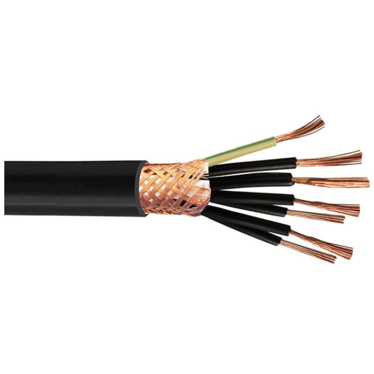
Specifying the wrong cable type for an application isn’t just a paperwork mistake — it causes insulation failures, nuisance tripping, overheated terminations, and in the worst cases, fires that shut a facility down for weeks. Procurement managers who treat cables as a generic commodity routinely discover the problem after installation, when fixing it means pulling conduit, re-terminating panels, and explaining unplanned downtime to plant management. Getting the classification right from the start is the shortest path out of that situation.
The two main types of cables are power cables and data/communication cables. Power cables carry electrical energy — from low-voltage distribution at 0.6/1 kV up to ultra-high-voltage transmission at 500 kV — and are built around high-conductivity copper or aluminum conductors with robust insulation systems. Data and communication cables transmit signals rather than energy, and their design priorities are controlled impedance, shielding, and bandwidth, not current-carrying capacity.
What makes this distinction genuinely useful on the plant floor is understanding that these two families have almost nothing in common beyond the word “cable” — different conductor sizing logic, different installation rules, different failure modes, and very different procurement lead times. The global cable market is on track to exceed USD 300 billion by 2030, and those two segments drive the bulk of it. Understanding why they diverged, and how each one is engineered for its job, is what keeps selection decisions defensible.
How Power Cables Are Engineered: Conductors, Insulation Layers, and Voltage Class Distinctions
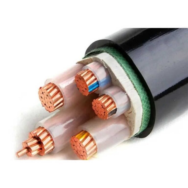
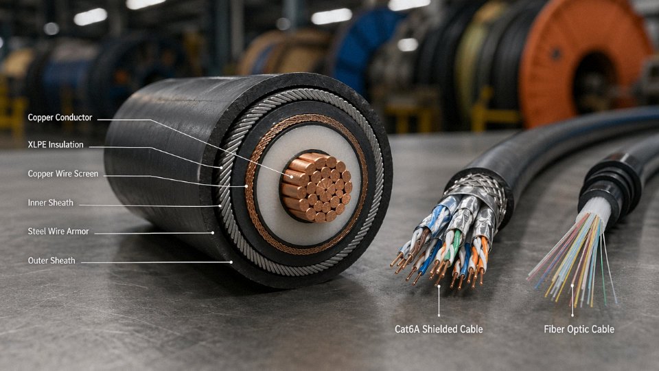
A power cable is not simply a wire wrapped in plastic. It’s a precisely layered system where each component does a distinct job, and getting any layer wrong — wrong insulation grade, undersized conductor, wrong armor type for the burial environment — shows up fast, usually as heat, partial discharge, or an outright fault. Understanding the construction logic helps you specify correctly the first time.
The Four Structural Layers and What Each One Actually Does
The conductor sits at the center and carries current. That’s obvious. What’s less obvious is how much the choice between copper and aluminum ripples through the rest of the project. Copper’s resistivity runs around 1.72 × 10⁻⁸ Ω·m; aluminum sits at roughly 2.82 × 10⁻⁸ Ω·m — about 64% higher. In practice, that means an aluminum conductor needs a cross-section roughly 1.5–1.6× larger than copper to carry the same current, which affects conduit sizing, termination hardware, and jointing labor. On the other hand, aluminum is typically 70% lighter per unit length, and on long overhead runs or large underground distribution projects where you’re pulling thousands of meters, that weight difference significantly reduces installation cost and tension load on support structures. There’s no universal right answer; the choice depends on route length, current density, and local material pricing at the time of procurement.
The insulation layer wraps directly around the conductor and must withstand continuous operating voltage, transient overvoltages, and thermal stress over a service life that’s typically specified at 30–40 years. XLPE (cross-linked polyethylene) dominates medium- and high-voltage applications because of its excellent dielectric strength, relatively low dielectric loss, and thermal rating up to around 90 °C continuous. EPR (ethylene propylene rubber) is used where flexibility is critical — think trailing cables on mobile equipment — and handles wet environments better than XLPE in some configurations. PVC insulation is largely confined to low-voltage cables; its dielectric performance degrades at higher temperatures, so you’ll rarely see it above 1 kV in any serious industrial specification.
The metallic shield (or screen) sits over the insulation and controls the electric field distribution — essential at medium voltage and above. Without it, field concentration at irregularities causes partial discharge, which degrades insulation incrementally until you get a failure. At high voltage, this layer is engineered with extreme care. Armoring, which is a separate layer from the screen, provides mechanical protection. Steel wire armoring (SWA) handles tensile loads in direct burial or vertical installations; steel tape armoring (STA) is cheaper and adequate for horizontal duct runs where tensile stress is low; aluminum wire armoring (AWA) is specified where magnetic losses matter — three-phase single-core cables in particular, because a steel armor on a single-core AC cable creates an eddy-current heating problem that AWA avoids.
The outer jacket — usually PVC, HDPE, or LSZH — is the environmental barrier. For direct burial in aggressive soil, HDPE outperforms PVC. In tunnel or building installations with fire safety requirements, LSZH (low-smoke zero-halogen) compound is increasingly mandated.
Voltage Classification: Why the Boundary Lines Matter for Specification
Low-voltage cables at 0.6/1 kV cover the bulk of building wiring, panel feeds, and light industrial distribution — high volume, relatively standardized, governed primarily by IEC 60502-1. Medium-voltage cables in the 6–35 kV range serve distribution networks, industrial substations, and wind farm collector systems; IEC 60502-2 applies here, and the jump in construction complexity is real: you now need the conductor screen, insulation screen, and metallic sheath as mandatory elements, not optional ones.
High-voltage cables from 66 kV up to 220 kV fall under IEC 60840, and the manufacturing tolerances tighten considerably — insulation eccentricity, surface smoothness of the conductor screen, and cleanliness of the production environment all become critical variables. Above 150 kV, IEC 62067 takes over, covering the EHV and UHV range up to 500 kV used in grid backbone transmission. At these voltage levels, cable systems are engineered and qualified as complete systems — joint and termination design, installation method, and the cable itself are all interdependent.
Jinda's power cables are manufactured and tested to IEC 60502, IEC 60840, and IEC 62067 standards, supporting global export projects across more than 50 countries.True
These IEC standards are internationally recognized benchmarks for power cable design, testing, and performance qualification. Alignment with these standards is a verifiable compliance requirement for international supply contracts, and Jinda's production infrastructure and export footprint support this claim.
Specifying the wrong voltage class is one of the more common procurement errors — typically under-specifying by one tier to save cost, then discovering that the cable’s partial discharge test threshold doesn’t meet the actual system requirement. The correction at that point costs far more than the original price difference.
Communication and Data Cables Decoded: Signal Integrity, Shielding Strategies, and Bandwidth Demands
Where power cables move energy, communication cables move information — and the engineering priorities flip almost completely. Conductor cross-section shrinks from tens of square millimeters down to fractions of a millimeter. The dominant performance metrics shift from current-carrying capacity and insulation voltage class to characteristic impedance, attenuation, crosstalk, and return loss. Getting these parameters wrong doesn’t trip a breaker; it degrades signal quality invisibly until a network drops packets, a SCADA sensor reads noise as process data, or a video feed stutters in a security-critical environment.
The Main Sub-Families and What Separates Them
Twisted-pair copper cables — Cat5e through Cat8 — remain the workhorse of structured cabling in commercial buildings and light-industrial Ethernet runs. The twist rate is not arbitrary: tighter twists suppress electromagnetic interference by ensuring that induced noise cancels across each differential pair. Cat5e handles 1 Gbps up to roughly 100 m; Cat6A pushes 10 Gbps over the same distance with tighter geometry and improved alien crosstalk rejection; Cat8 targets 25–40 Gbps but only over runs of 30 m or less, which limits it largely to patch applications in data center top-of-rack setups. The difference between Cat6 and Cat6A in a dense cable tray is not trivial — Cat6A is physically fatter, runs hotter under load, and needs larger conduit allowances. Plan for that early.
Coaxial cables handle a different problem: single-conductor RF signal transmission with a controlled 50 Ω or 75 Ω impedance environment. The geometry — center conductor, dielectric, braided shield, jacket — is rigid by design, because impedance discontinuities reflect signal energy back toward the source. Even a poorly crimped connector adds measurable return loss. Coax still appears in antenna feeds, CCTV trunk lines, and certain industrial sensor connections where frequency range matters more than multi-pair density.
Shielding: Matching Architecture to Environment
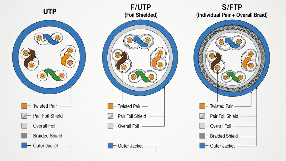
This is where a lot of procurement decisions go wrong. UTP is fine in a clean office environment with no heavy machinery nearby. On a factory floor running variable-frequency drives, motor starters, or high-current bus bars within a few meters of signal cabling, UTP is asking for trouble. Foil-shielded twisted pair (FTP or F/UTP) gives you an overall aluminum-mylar barrier against high-frequency interference. Individually shielded pairs — SFTP or S/FTP — add per-pair foil plus an overall braid, which is the standard specification for Cat7 and Cat8 and the right choice for dense industrial EMI environments or long outdoor conduit runs where the cable picks up interference along its entire length.
Shielded cables (STP/SFTP) always outperform UTP in all environmentsFalse
In environments with poor or inconsistent grounding, a shielded cable improperly terminated can actually introduce noise rather than reject it. Shield grounding practice — single-point versus multi-point, depending on frequency — matters as much as the shield itself. UTP with correct cable routing sometimes outperforms poorly grounded STP.
Fiber Optic Cables: Where Copper Physics Hits Its Limit
Beyond roughly 100 m at 10 Gbps, or anywhere electromagnetic isolation is mandatory, fiber optic cable is the rational choice. Single-mode fiber (OS2, 9 µm core) carries signal over kilometers with attenuation in the range of 0.2–0.4 dB/km depending on wavelength, and supports 100 Gbps per wavelength — multiply that by dozens of channels with DWDM and the capacity becomes almost absurd by copper standards. Multimode fiber (OM3, OM4, OM5) trades distance for lower transceiver cost, practical for 300–550 m at 10 Gbps in data center backbone runs.
Loose-tube construction protects fibers in outdoor and direct-burial applications where thermal cycling and mechanical stress are real. Tight-buffered construction suits indoor riser and plenum runs where termination density and flexibility matter more than ruggedness.
Instrumentation Cables: The Industrial Signal Layer
Instrumentation cables occupy the uncomfortable middle ground between power and data — low-voltage analog signals (4–20 mA loops, thermocouple pairs, pulse outputs from flow meters) running through environments saturated with electrical noise. The cables are typically multi-pair, individually shielded, with drain wires on each pair for grounding at the control panel end only. Running an unshielded instrumentation cable parallel to a 480 V motor feed in the same tray is one of the most reliable ways to generate ghost readings in a process control system. In practice, physical separation of at least 150–300 mm, or a dedicated metallic divider in a shared tray, is the minimum acceptable standard on most plants I’ve seen.
The signal type matters too: thermocouples require matched extension cable with the same alloy composition as the thermocouple itself, or the junction at the cable end introduces a measurement error that looks exactly like a calibration drift.
Comparing Power and Communication Cables Side by Side: Voltage, Current, Frequency, and Loss Parameters
The two cable families look superficially similar on a reel. Pull back the jacket and the engineering logic diverges completely — different conductor sizing philosophy, different loss mechanisms, different international standards bodies, and very different consequences when you specify the wrong one.
The Numbers That Actually Separate Them
| Parameter | Power Cables | Communication / Data Cables |
|---|---|---|
| Operating voltage | 0.6/1 kV (LV) up to 500 kV (UHV) | Typically < 100 V signal; PoE up to ~57 V DC |
| Current-carrying capacity | Tens to thousands of amperes, derated by IEC 60287 thermal method | Milliamps to low single-digit amps; ampacity rarely the design constraint |
| Frequency | DC or 50/60 Hz (power frequency) | MHz to GHz range for high-speed data; DC for some fieldbus |
| Primary loss mechanism | Resistive I²R heating in conductor | Dielectric loss, impedance mismatch, reflection, attenuation per unit length |
| Governing standards | IEC 60228, IEC 60502, IEC 60840, ICEA | IEC 61156, TIA-568, ISO/IEC 11801, ITU-T G.652 (fiber) |
Copper’s resistivity of roughly 1.72 × 10⁻⁸ Ω·m versus aluminum’s 2.82 × 10⁻⁸ Ω·m — that gap matters enormously in a 240 mm² power feeder carrying 400 A over 500 meters; it’s largely irrelevant in a Cat6A patch cable where the conductors are 23 AWG and current is measured in milliamps. Different physics, different optimization targets.
Optimization Logic: Thermal Dissipation vs. Signal Integrity
Power cable engineering is fundamentally a thermal management problem. IEC 60287 lays out the heat-transfer equations — conductor loss, dielectric loss in HV cables, armor loss — and the allowable continuous current rating falls out of that thermal budget given soil resistivity, burial depth, grouping factor, and ambient temperature. Get the derating wrong and you’re looking at accelerated insulation aging or, in a worst case, a thermal runaway event in a grouped duct bank. Experienced cable engineers will tell you the IEC 60287 calculation is only as good as the soil data, which is often the weakest input on the whole project.
Communication cable design lives in a different world — impedance matching, return loss, near-end crosstalk (NEXT), and phase consistency across the bandwidth of interest. A shielded Cat6A cable is engineered to maintain 100 Ω ± 15% characteristic impedance from DC up past 500 MHz. Single-mode fiber sidesteps conductor physics entirely; attenuation in the 0.2–0.4 dB/km range (depending on wavelength and fiber grade) makes it the right answer the moment the run length gets long enough to make copper loss budgets painful.
Hybrid Assemblies: Where They Help and Where They Bite You
Composite cables — a power core and a data pair or fiber element sharing one outer jacket — are genuinely useful in specific situations. Wind turbine towers are a good example: running separate cable trays up a 100-meter tower for power and control adds cost and weight, so a composite tray cable with 3–4 power cores plus screened pairs makes real sense. Same logic applies to industrial robot umbilicals and some mining trailing cables where you simply cannot manage separate harnesses in a moving application.
The complications are real though. Bundling a 400 V power core next to signal pairs creates ground loop risk and induced noise, particularly if the power cores carry variable-frequency drive output (which is electrically ugly — high dV/dt switching transients). You’ll need individual pair shielding, and the power cores must be derated because the composite bundle runs hotter than the power cable would alone. That derating is easy to forget under procurement pressure.
Hybrid composite cables always require ampacity derating compared to standalone power cables of the same conductor cross-section.True
Bundling power cores with signal elements increases thermal resistance and reduces heat dissipation, which lowers the allowable continuous current per IEC 60287 grouping and proximity correction factors.
Budget Calibration for Procurement Teams
Rough installed cost ranges — these vary with copper price, conduit system, labor market, and project scale:
- LV copper power cable, 4-core 16 mm², installed: roughly USD 8–15 per meter (higher end in urban conduit work, lower in direct-buried bulk runs)
- Cat6A shielded twisted pair, installed: USD 2–5 per meter, heavily dependent on termination density and patch panel count
- Single-mode fiber optic cable, installed: USD 1–4 per meter for the cable itself, but fusion splicing and testing add cost that can dwarf the cable material cost on short runs
Fiber looks cheap per meter until you count the splice enclosures, OTDR commissioning time, and the fact that a nicked fiber in a concrete pour is a full re-pull. For runs under roughly 90 meters in a clean industrial building, Cat6A often wins on total installed cost even if the per-meter number looks higher.
The Decision in Plain Terms
If the application moves watts across distance — motors, lighting, HVAC, transformers — specify a power cable sized by ampacity and voltage class. If the application moves bits or analog signals — Ethernet, fieldbus, video, SCADA — specify a communication cable sized by bandwidth, shielding class, and run length. Hybrid needs get a composite cable or parallel routing, chosen based on whether the interference risk and derating penalty is acceptable. That’s the whole decision tree.
Industry-Specific Application Mapping: Which Cable Type Dominates in Each Sector
The technical distinctions between power and communication cables only matter if you can map them to real installations. Here’s how that shakeout actually looks across the major sectors.
Power Generation and Grid Infrastructure
This is where high-voltage XLPE-insulated power cables earn their keep. Transmission corridors running at 220 kV or 500 kV demand cable systems engineered for decades of uninterrupted service — any insulation defect or joint failure triggers outages that cascade across entire grid regions. Offshore wind is arguably the most demanding procurement challenge right now: 66 kV and 132 kV three-core submarine export cables have to handle the mechanical abuse of J-tube pull-ins, dynamic fatigue near the hang-off point, and seawater ingress risk simultaneously. Lead times on these cables can stretch to 18–24 months depending on conductor cross-section and armoring configuration, so project teams that treat them as a late procurement item will delay commissioning.
Solar farm DC collection cables sit at the opposite voltage end — typically rated at 1.5 kV DC or 1.8 kV DC — but they run at continuous high current densities in ambient temperatures that push 60–70 °C at ground level in desert sites. Thermal rating, UV stabilization of the jacket, and resistance to partial discharge under DC stress are the real engineering criteria here, not just voltage class.
Building and Construction
Modern commercial buildings run two essentially separate cable infrastructures in parallel. The LV power side — multicore cables feeding distribution boards, lighting circuits, HVAC drives, and lift systems — is usually specified to fire-resistance standards like IEC 60331 (circuit integrity) and IEC 60332 (flame spread). Get that wrong in a high-rise and the consequence isn’t just a failed inspection; it’s a building that loses emergency lighting during evacuation.
The structured cabling side — Cat6A horizontal runs, OM4 or OS2 fiber backbones, coax for CCTV — carries building automation, access control, and IT traffic. These cables share the same cable trays and risers as the power cables, which is precisely why EMC segregation rules matter in practice. A run of Cat6A too close to a VFD feeder cable will show up as intermittent network faults that take a frustrating amount of time to diagnose.
Oil, Gas, and Petrochemical
Hazardous area work — ATEX/IECEx Zone 1 and Zone 2 classification — demands armored instrumentation cables and fire-resistant control cables that are certified, documented, and traceable. The instrumentation cables running 4–20 mA signals or thermocouple pairs need individual and collective shielding to survive the electrical noise environment near compressors and variable-speed drives. Subsea umbilical cables deserve a mention here because they’re genuinely unusual assemblies: a single umbilical might bundle power conductors, fiber optic elements, hydraulic hose, and chemical injection tubing, all within one armored sheath. Procurement on these is highly engineered and almost always project-specific.
Transportation and Rail
Rolling stock cables have to satisfy EN 50264 or EN 50306 — flame, smoke, and toxicity requirements that go beyond standard IEC categories because passengers are in an enclosed space. Traction power cables on the vehicle handle high pulsed currents; signaling cables alongside the track need to maintain signal integrity against traction-frequency interference. Leaky coaxial cables in tunnels are a niche but essential product: they act simultaneously as antenna and transmission line, providing continuous radio coverage where conventional antennas can’t reach.
Data Centers and Telecommunications
Hyperscale data centers are heavy consumers of pre-terminated MPO fiber trunks, LSZH-jacketed Cat8 patch cords, and high-density fiber distribution assemblies. The fire and emissions requirements drive the LSZH specification — halogen-containing jackets are simply not acceptable in raised-floor environments where maintenance staff work in confined spaces. Power cables in these facilities are also heavily specified: busway systems and redundant UPS feeder cables have to meet tight voltage drop budgets.
Manufacturing and Industrial Automation
Continuous-flex cables for robot arms and drag chains are where cable quality becomes visible almost immediately. A cable that meets the mechanical flex cycle rating — often 5 to 10 million cycles depending on the application — will last years; one that doesn’t will crack the conductor or jacket within months, causing intermittent faults on a production line that are genuinely difficult to locate. PROFIBUS, DeviceNet, and Industrial Ethernet cables have specific impedance and capacitance requirements that affect bus performance at distance; substituting a generic shielded cable because it looks similar is a reliable way to introduce communication errors that only appear under load.
Leaky coaxial cables function as both transmission line and distributed antenna in tunnel installations.True
Leaky coaxial cable (also called radiating cable) has slots or apertures in its outer conductor that allow controlled RF energy to radiate along its length, providing continuous radio coverage in tunnels — confirmed in rail and metro system engineering standards including EN 50117 and documented in IEC technical references.
Material Science Behind Cable Performance: Insulation, Jacketing, and Conductor Choices Explained
The gap between a cable that lasts 30 years and one that fails in five usually comes down to material selection — not installation error, not brand reputation, not price tier. Engineers who understand polymer behavior and conductor metallurgy can catch specification mismatches before they become warranty claims or unplanned outages.
Insulation Polymers: Four Materials That Cover Most Real Applications
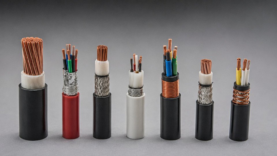
PVC is everywhere in low-voltage power cables, and for good reason: it’s cheap, flexible enough for most fixed-wiring runs, and tolerates the kinds of physical abuse that happens on a busy construction site. The ceiling, though, is real. PVC insulation is rated for conductor operating temperatures in the range of 70°C, and pushing past that — even briefly and repeatedly — accelerates plasticizer migration, embrittlement, and eventually insulation cracking. In confined cable trays running at high load density, that limit gets reached faster than specifiers expect.
XLPE — cross-linked polyethylene — is the material that made modern medium- and high-voltage cable construction practical. Cross-linking converts thermoplastic polyethylene into a thermoset structure: continuous operating temperature rises to around 90°C, and short-circuit withstand goes up to roughly 250°C depending on conductor cross-section and duration. That thermal headroom translates directly into higher current-carrying capacity for a given conductor size, which matters when you’re trying to fit 15 circuits into a tray that was sized for 10. Most MV cables from 6 kV up to 35 kV and essentially all EHV transmission cables above 110 kV use XLPE today.
EPR (ethylene propylene rubber) doesn’t get the attention it deserves outside marine and mining circles. Its dielectric properties remain stable across wide temperature swings, it handles moisture far better than XLPE in poorly drained duct installations, and the inherent flexibility of the rubber matrix makes it practical for cables that move — pump cables, trailing cables on mining machinery, shipboard feeders. The trade-off is cost: EPR compounds run noticeably higher than XLPE per kilogram.
PTFE sits at the opposite end of the cost curve and the performance curve simultaneously. Its dielectric constant of approximately 2.1 is among the lowest of any solid insulating material, which makes it the default choice for aerospace signal cables and high-frequency coaxial assemblies where propagation delay and signal integrity are tightly controlled. You won’t find it on a power distribution project unless someone is specifying instrument wiring inside a furnace enclosure.
Dielectric Properties and Why They Govern Communication Cable Performance
For communication and data cables, the two numbers that dominate material selection are dielectric constant (εr) and dissipation factor (tan δ). Lower εr shortens signal propagation delay — relevant in high-speed differential pairs where timing skew between conductors causes bit errors. Lower tan δ means less dielectric heating at high frequencies, which keeps attenuation figures honest and prevents performance degradation as the cable ages in a warm ceiling plenum.
Solid polyethylene insulation gives εr values around 2.25–2.3. Foam-PE constructions — where the polyethylene is expanded with nitrogen or a chemical blowing agent to introduce air voids — drop εr down to roughly 1.4–1.6 depending on void fraction. That’s why foam-insulated coaxial and structured-cabling cores consistently outperform solid-PE designs at Cat 6A frequencies and above, and why high-frequency RF coax almost universally specifies foam dielectric rather than solid.
Jacket Compounds: The Environmental Interface Nobody Should Ignore
Jacket selection is frequently treated as an afterthought. It shouldn’t be. In a public building — a hospital, a transit station, a school — LSZH (low-smoke zero-halogen) jacketing is not optional; it’s a code requirement under IEC 60754 and EN 50399 in most jurisdictions. The engineering rationale is straightforward: in a fire, conventional PVC jackets release hydrogen chloride gas, which is toxic at relatively low concentrations and damages electronic equipment far from the fire origin. LSZH compounds eliminate chlorine from the formulation entirely.
Industrial drag-chain and robot-tether cables present a completely different failure mode: the jacket must survive cyclic flexing, abrasion against cable carriers, and intermittent contact with cutting fluids or hydraulic oil. Polyurethane (PUR) handles that environment well — its tear resistance and chemical resilience are noticeably better than PVC, and a well-specified PUR jacket on a drag-chain cable can extend service life from roughly 1–2 million flex cycles (PVC) to 5–10 million cycles, depending on bend radius and travel speed.
Outdoor cables exposed to direct sun and atmospheric ozone — irrigation pump cables, overhead bundled conductors in some markets, solar farm home-run cables — benefit from chlorinated polyethylene (CPE) or cross-linked polyolefin jackets. UV degradation of an undersized or wrong-compound jacket is a slow failure: chalking first, then surface cracking, then water ingress along the conductor, then insulation failure that traces back to a material spec error made three years earlier.
Conductor Temper and Stranding: Details That Affect Flex Life and Fill Factor
Copper conductor isn’t a single product. Annealed (soft-drawn) copper bends without work-hardening, which is why it goes into flexible cords, appliance leads, and fine-wire communication cables. Hard-drawn copper resists elongation under tension, making it appropriate for overhead conductors and fixed rigid wiring where mechanical load is constant.
For power cables, compressed and compacted stranding reduces the air gaps between individual wires, shrinking overall conductor diameter by roughly 3–8% compared to a conventional round stranded conductor of the same cross-section. That reduction in diameter flows directly into smaller overall cable OD, better tray fill efficiency, and slightly lower material cost on insulation and jacket. It’s not a dramatic difference on a single cable, but across a large substation project with hundreds of circuits, the savings in conduit size and pull-in labor add up.
Communication cables typically use fine-wire bunched conductors — sometimes 7, 19, or 49 individual wires depending on the flex class required — to handle the repeated bending without individual wire fracture. A data cable serving a moving machine arm that fails from conductor fracture rather than insulation breakdown is almost always a case where a fixed-installation cable was incorrectly installed in a flex-duty application.
Jinda produces XLPE-insulated medium-voltage power cables rated up to 35 kV and has R&D programs focused on halogen-free flame-retardant (HFFR) compound development for both power and communication cable product lines.True
This reflects Jinda's documented production capabilities across five manufacturing bases in China and its stated product range for international project supply.
Jinda’s investment in HFFR compound development is a direct response to tightening fire-safety codes across the European, Middle Eastern, and Southeast Asian markets the group supplies. For procurement teams sourcing cables for projects with mixed power-and-data requirements across multiple building types, the ability to source both XLPE MV power cables and LSZH-jacketed structured cabling from a single qualified manufacturer meaningfully simplifies vendor qualification and traceability documentation.
International Standards and Certifications That Govern Cable Selection for Cross-Border Projects
Cross-border cable procurement is where technical specifications and trade compliance collide — and it’s messier than most project specs acknowledge. A cable perfectly suited to the application can still fail customs clearance, get rejected by a third-party inspector, or void an insurance policy if the certification paperwork doesn’t match the destination market’s requirements. Engineers who’ve run international projects know this. It wastes weeks.
The Major Standards Bodies and Where They Actually Apply
IEC is the practical global baseline. Most national standards either adopt IEC documents directly or derive from them, which means a cable certified to relevant IEC standards has a reasonable starting point almost everywhere. That said, “IEC compliant” is not a pass-everywhere stamp — local regulators frequently add requirements on top.
CENELEC harmonized standards (EN series) are mandatory for CE marking in the EU. Post-Brexit, the UK now maintains its own BS standards under UKCA marking — the two frameworks have diverged in places, so a cable specified for an EU project cannot automatically be assumed UKCA-compliant for a UK installation, particularly for fire performance classifications. This distinction catches procurement teams off guard more often than it should.
North America runs on a parallel system. UL listings under the National Electrical Code (NEC) framework govern the US market; CSA handles Canada with some overlap. A critical operational point: there’s a real difference between a UL-listed product and a UL-recognized component. A UL-recognized component has only been evaluated as part of a larger assembly — it cannot be installed as a standalone product in a UL-jurisdiction project. Procurement managers ordering cables for US installations who don’t verify this distinction are asking for rejection on-site.
Australia and New Zealand use AS/NZS standards, which are partially aligned with IEC but carry specific local requirements for installation categories and flame performance. GB/T covers China’s domestic market and is increasingly accepted in Belt and Road corridor projects, Southeast Asian markets, and some Middle Eastern tenders — though not universally, and acceptance should be verified project by project rather than assumed.
Key IEC Standards by Cable Type
For power cables, IEC 60502-1 covers extruded solid dielectric insulated power cables rated 1 kV to 30 kV; IEC 60502-2 extends this to 30 kV through 150 kV. Flexible power cables fall under IEC 60227 (PVC-insulated) and IEC 60245 (rubber-insulated). Data and multicore symmetrical pair cables are governed by IEC 61156, which directly influences Cat 6A and similar structured cabling specifications. Fiber optic cables follow IEC 60794, a substantial document family given how many fiber types, connector arrangements, and deployment environments now exist.
Fire performance is where the standards get particularly layered. IEC 60332 series addresses flame propagation — IEC 60332-1 for single cables, IEC 60332-3 for bunched installations, which is the relevant test for cable trays in commercial or industrial buildings. IEC 61034 governs smoke density. Both matter for life-safety compliance in occupied buildings.
CE Marking and the CPR Euroclass System
Cables sold into EU buildings must comply with the Construction Products Regulation (CPR). The Euroclass fire performance system runs from Aca (highest performance — generally limited to optical fiber cables with no combustible elements) down through B1ca, B2ca, Cca, Dca, Eca to Fca. Specifying the wrong Euroclass for a hospital, school, or public transport installation isn’t just a compliance failure — it’s a liability exposure. Euroclass requirements must appear in the cable’s Declaration of Performance (DoP), and the DoP must accompany the product.
Jinda cables carry IEC, CE, and ISO 9001 certifications alongside country-specific approvals covering more than 50 destination markets.True
Jinda's documented certification portfolio is cited in their official company profile and supports verified customs clearance and tender submission across multiple regulatory jurisdictions.
Why Certification Documentation Is a Procurement Asset, Not a Formality
Project tenders in the Gulf, European infrastructure projects, and Australian industrial installations increasingly require third-party certified test reports, not just supplier declarations. Insurance underwriters for large installations want to see the documentation trail. Customs authorities in multiple markets now scrutinize cable certification as part of product safety compliance — not just for tariff classification.
Working with a manufacturer that maintains an active, audited certification portfolio shortens this process considerably. Jinda’s approvals covering IEC, CE, ISO 9001, and destination-market-specific certifications mean that documentation packages for tender submission, customs clearance, and project commissioning can be assembled without chasing third parties mid-procurement cycle — which, in practice, is where delays actually occur.
Sourcing, Procurement, and Quality Verification: How to Evaluate a Cable Supplier for Large-Scale Projects
The global cable market is large enough — projected past USD 300 billion by 2030 — that it attracts a predictable share of substandard product. If you’ve been in procurement long enough, you’ve seen it: drums arriving on site that measure out under spec, insulation that cracks during installation in cold weather, test certificates that don’t match the production batch. These aren’t edge cases. They’re routine problems in international cable sourcing, and the consequences range from a costly retest-and-replace cycle to an energized fault in a finished installation.
The Most Common Quality Failures to Screen Against
Undersized conductors are probably the most widespread issue. Actual cross-sections running 10–25% below nominal are achievable by simply drawing the wire slightly finer — a small change per meter that compounds enormously across a 3,000-meter drum. The conductor resistance test per IEC 60228 catches this directly; a 95 mm² copper conductor has a maximum DC resistance of 0.193 Ω/km at 20°C, and anything meaningfully above that tells you the conductor isn’t what the label says. Weight-per-unit-length verification is a blunt but effective cross-check — weigh a measured section, calculate back to cross-section, compare to nominal. It takes 10 minutes on the loading dock and has caught more problems than any paperwork review.
Substandard insulation compound is harder to detect visually but shows up in dielectric strength testing and accelerated aging. Some suppliers substitute lower-grade XLPE or PVC blends that meet no particular standard, reducing both dielectric strength and long-term heat resistance. In medium-voltage applications especially, this shortens service life in ways that won’t appear until year three or four of operation — well past any contractual warranty claim period.
Armor coverage gaps and falsified certificates round out the common failure list. Armor that looks correct on a cross-section photograph but is wound at too great a lay angle, or uses undersized wires, will fail mechanical protection under real installation loads. And certificates can be reused across batches or simply fabricated; without traceable sample identification linking a specific certificate to a specific production lot and cable length, the document is decorative.
The Audit Checklist That Actually Matters
When qualifying a supplier or auditing an existing one, the verification items worth your time are: conductor DC resistance per IEC 60228 on production samples, insulation spark test and high-voltage withstand per IEC 60502 on every production length, conductor weight-per-meter cross-check against nominal cross-section, and third-party laboratory reports with traceable sample IDs — not just the supplier’s own in-house test records. Ask for the production batch traceability records that connect raw material coil numbers to finished drum numbers. A capable factory can produce this without hesitation. One that can’t, or stalls, tells you something.
Understanding Routine, Type, and Sample Tests — and Why It Matters in Your Purchase Order
These three test categories are frequently conflated, and the confusion costs buyers money or leaves them underprotected. Routine tests run on every production length — conductor resistance, insulation resistance, high-voltage withstand. They’re the baseline and should be non-negotiable in your PO terms. Type tests are performed once on a given design to prove it can handle impulse withstand, bending radius, and thermal load cycling; they validate the design, not the production batch. Sample tests sit in between — statistical sampling of production batches to catch process drift. Specifying all three categories correctly in your purchase order, rather than just asking for “test certificates,” closes the gap that substandard suppliers exploit.
Lead Times, Logistics, and Incoterms for Large Orders
Production lead times for cable orders typically run 4–12 weeks, depending on conductor cross-section, voltage rating, and whether specialty materials (halogen-free compound, LSZH jacketing, armoring type) are involved. A standard 0.6/1 kV power cable in a common cross-section might be 4–6 weeks from a well-stocked manufacturer; a 35 kV medium-voltage cable with a non-standard cross-section runs closer to 8–12 weeks, sometimes longer if copper rod supply is constrained.
Drum sizing and containerization require attention before the order ships. A standard 22-metric-ton FCL can accommodate roughly 8–12 large cable drums, but this varies considerably with drum diameter — a 2.2-meter drum takes up floor space regardless of its weight, and the actual limiting factor is often cubic volume rather than tonnage. Get drum dimension specs early and run the containerization math before confirming quantities per shipment.
For incoterms: FOB Qingdao or FOB Shanghai works well for buyers with established freight forwarders and marine insurance. CIF to destination port reduces buyer complexity on the ocean leg but shifts risk transfer to port of destination, which matters for damage claims. DDP suits smaller buyers or those unfamiliar with import customs in their country, though the landed cost premium is real.
Jinda operates five manufacturing bases covering 470,000 m² with in-house raw material processing and a dedicated export documentation team.True
These figures reflect Jinda's stated operational capacity and are consistent with an established manufacturer serving customers in over 50 countries since 1987.
Why Consolidated Sourcing From a Single Audited Supplier Reduces Risk
Splitting power cable and communication cable procurement across multiple suppliers introduces version-control problems on certification documents, complicates batch traceability, and creates logistics coordination overhead that eats into project management time. A manufacturer with integrated production — conductors, insulation compounding, armoring, and jacketing under one quality system — gives procurement a single audit target and a single point of accountability for test records.
Jinda’s five production bases and 470,000 m² of manufacturing capacity are sized for exactly this kind of consolidated, large-volume export supply. In-house raw material processing means fewer external variables in the supply chain, and a dedicated export documentation team handles the certificate-of-origin, test report, and customs paperwork that turns into a project delay when it’s handled ad hoc. After-sales technical support — actual engineers who can answer installation questions, not just a sales contact — closes the loop on what is otherwise a gap in most cable supplier relationships.
For buyers running large infrastructure, industrial, or energy projects: the procurement risk in cable is real, the verification tools exist and aren’t complicated, and consolidating with a supplier who can be audited end-to-end is worth the effort before you’re troubleshooting a field failure.
Frequently Asked Questions About the Two Main Types of Cables
Can a power cable carry signals, and can a communication cable carry power?
Power cables can carry low-frequency pilot signals superimposed on the AC supply — this is the basis of powerline communication (PLC) systems used in smart metering and ripple control. It works, but there are real limits. Power cable geometry is optimized for current-carrying capacity, not signal transmission: capacitance per unit length is high, impedance is uncontrolled, and attenuation climbs sharply above a few hundred kilohertz. Trying to push 100 Mbit/s Ethernet over a 10 kV XLPE feeder is not a practical option.
The reverse case is more dangerous than it is merely impractical. A Cat 6 UTP data cable is designed for signal currents measured in milliamps. Apply power-cable current levels — even 10 A at low voltage — and the 24 AWG conductors will heat rapidly, the polyethylene dielectric will soften, and insulation failure follows. Keep the two families strictly separate unless you are working with a purpose-built hybrid product rated for both functions.
What is the difference between a wire and a cable?
A wire is a single conductor — one metal element, bare or with a primary insulation layer over it. A cable is an assembly: either two or more insulated conductors bound together, or a single conductor surrounded by a complete system of layers (insulation, screen, armor, jacket) intended as a finished wiring product. NEC Article 100 uses roughly this logic, and IEC terminology follows the same principle. In practice, the distinction matters for conduit fill calculations and for procurement — ordering “wire” when you need “cable” has caused more than a few project delays.
Is fiber optic cable a power cable or a communication cable?
Standard fiber optic cable is a pure communication medium. It carries photons, not electrons, so it delivers no electrical energy to the far end. Electrically, it is essentially inert — which is exactly why it is specified in environments where galvanic isolation or EMI immunity is critical.
The niche exception is power-over-fiber (PoF) systems, where a small photovoltaic cell at the receiving end converts light to electricity for remote low-power devices. These exist in hazardous-area instrumentation and certain defense applications, but the power levels are milliwatts. This is an interesting overlap, but it does not change the fundamental classification of fiber as a communication cable.
Copper or aluminum conductor — how do I decide?
Copper resistivity runs around 1.72 × 10⁻⁸ Ω·m versus roughly 2.82 × 10⁻⁸ Ω·m for aluminum, which means aluminum needs approximately 1.6× the cross-sectional area to match copper’s ampacity. That larger cross-section, combined with aluminum’s lower density, still results in a lighter, cheaper cable at large sizes — which is why you see aluminum dominating overhead transmission lines and large underground MV feeders in the 185–400 mm² range.
Copper stays the right choice for confined installations where physical space limits conductor size, for flexible cables where repeated bending demands ductility, and for terminations where the smaller cross-section simplifies connection hardware. On long overhead runs or bulk feeder projects, run the numbers both ways. The aluminum option often saves 20–40% on conductor cost depending on market conditions, though the exact figure shifts with LME copper and aluminum prices on the day you buy.
What does XLPE mean, and why does it dominate modern power cable insulation?
XLPE stands for cross-linked polyethylene. Standard polyethylene is a thermoplastic — it softens and flows when hot, which limits it to relatively modest continuous operating temperatures. Cross-linking — achieved by peroxide chemistry, silane moisture cure, or electron-beam irradiation — creates covalent bonds between adjacent polymer chains, converting the material into a thermoset that cannot melt. The result is a continuous operating temperature of 90°C versus 70°C for PVC, a significantly higher short-circuit temperature rating (up to 250°C depending on the standard), lower dielectric losses, and better long-term moisture resistance.
For medium- and high-voltage applications, those properties compound: lower losses mean less heat generated per kilometer, which allows smaller cross-sections or higher sustained current, and the moisture resistance extends reliable service life in direct-buried or submarine installations. PVC still makes sense for low-voltage flexible cables and cost-sensitive LV fixed wiring where the thermal and dielectric advantages of XLPE do not justify the price difference.
How long do power cables and communication cables typically last?
IEC-rated XLPE insulated HV cables are designed for a 40-year service life under rated operating conditions — though that assumes correct installation, no sustained overloading, and no mechanical damage events. LV PVC fixed-wiring cables in controlled indoor environments realistically reach 25–30 years before insulation degradation becomes a concern; outdoor or thermally stressed installations age faster.
Outdoor fiber optic cables — gel-filled, with UV-stabilized HDPE jackets — are typically warranted for 20–25 years, with actual service life depending heavily on installation quality and exposure to rodent damage or freeze-thaw cycling. Industrial flexible cables are rated differently: expect 1–5 million flex cycles on a properly specified flexible conductor, but that range is extremely sensitive to bend radius, torsion, and whether the cable was sized for the actual flex duty from the start.
IEC-rated XLPE HV cables are designed for a 40-year service life under rated conditionsTrue
IEC 60840 and IEC 62067, which govern HV and EHV extruded cables, specify a 40-year design life as the standard basis for qualification testing and cable system design, assuming cables operate within rated voltage, temperature, and mechanical parameters throughout service.
What is the minimum information needed to specify a power cable for procurement?
Six parameters, and if any one is missing, the quotation process stalls or — worse — you get a cable that technically meets an incomplete specification but fails in service.
First, rated voltage expressed as U₀/U in kV (for example, 6/10 kV). Second, conductor material and nominal cross-section in mm². Third, number of cores. Fourth, insulation type (XLPE, PVC, EPR, etc.). Fifth, armor type if required — steel wire armored, steel tape armored, or unarmored. Sixth, outer jacket material and the governing standard.
A complete specification reads something like: IEC 60502-1, XLPE insulated, PVC outer sheath, steel wire armored, 3-core 95 mm² aluminum conductor, 6/10 kV. That single line tells a competent manufacturer everything needed to produce and test to the correct requirements. Anything less opens the door to interpretation, and cable interpretation errors have a way of surfacing at the worst possible moment — during commissioning, not at the factory.
Why Jinda’s Integrated Manufacturing Platform Supports Both Cable Families at Global Scale
Most large electrical infrastructure projects generate a cable schedule that spans both families — high-voltage feeders running alongside fiber-optic trunk cables, armored power circuits sharing cable trays with screened instrumentation loops, flexible control cables terminating at the same switchgear panel as the 11 kV supply. Sourcing those from two or three different manufacturers sounds manageable on paper. In practice, it multiplies audit load, creates documentation mismatches at customs, and introduces the very real risk that your armored MV cable arrives six weeks before your control cable does, stalling a substation commissioning that has a contractual penalty clause attached to it.
That fragmentation problem is specifically what a fully integrated manufacturer addresses.
Complete Product Range Across Both Cable Families
Jinda’s production scope covers low-voltage power cables from 0.6/1 kV through medium-voltage XLPE-insulated cables up to 35 kV and high-voltage transmission cables reaching 110 kV and above — with the design and tooling to handle armored variants (SWA, AWA, double-steel-tape), fire-resistant and low-smoke zero-halogen constructions for tunnels and public buildings, and flexible reeling cables for mobile plant. On the communication and instrumentation side, the range includes screened instrumentation cables, multipair control cables, industrial Ethernet cables, and structured cabling products.
What that means for a project engineer is a single cable schedule submitted to one technical team, one set of factory audits, one quality file, one shipment coordination contact. The bill of materials gets reviewed against the actual production capability — not farmed out to a trading house that rebrands product from whichever mill had stock that week.
Production Infrastructure Built for Volume Without Shortcuts
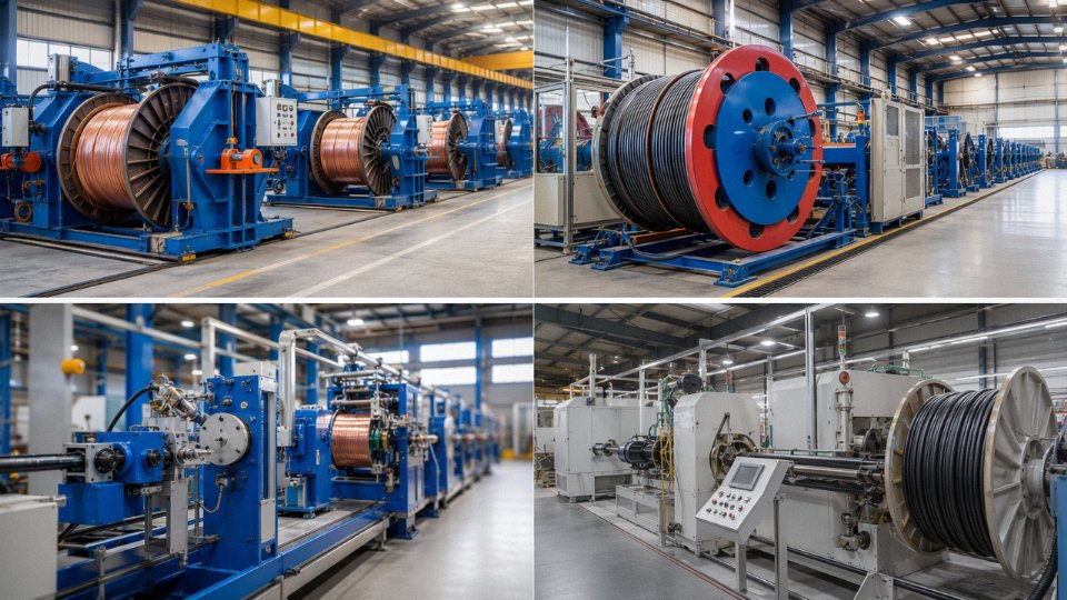
Five dedicated production bases, roughly 470,000 m² of total floor space — that scale matters when a project calls for, say, 800 km of 33 kV XLPE cable on a tight delivery window. Facilities of that size can run dedicated extrusion and stranding lines for different voltage classes simultaneously, which means a large MV order doesn’t compete for machine time with an LV flexible cable run. Subcontracting to fill capacity gaps is where quality control quietly breaks down; Jinda’s in-house capacity is sized to avoid it.
Over 1,000 employees across production, QC, and technical support roles. That headcount supports meaningful in-process inspection — not just end-of-line spark testing but conductor resistance verification lot by lot, insulation eccentricity measurement, and jacket thickness spot checks against IEC tolerances.
Jinda operates five production bases with over 470,000 m² of manufacturing space and exports to more than 50 countries.True
These figures are stated operational facts provided by the manufacturer and are consistent with an established large-scale cable group founded in 1987.
Export Infrastructure Designed for International Project Realities
Compliance documentation is genuinely tedious, and it’s where a lot of Chinese cable exports create friction at the receiving end. Jinda maintains certification alignment to IEC standards, CE marking where required, and country-specific approvals covering more than 50 export markets. Multilingual technical documentation — test reports, installation guides, drum schedules — reduces the back-and-forth that delays customs clearance or engineer approval on site.
Logistics is handled through established FCL and LCL partnerships, which matters for mixed-commodity shipments where power drums and communication cable reels need to consolidate efficiently. A dedicated after-sales technical team handles commissioning queries and field issues; in my experience, that post-shipment support is underweighted during supplier selection and painfully missed when something needs resolving 10,000 km from the factory.
Submit Your Cable Schedule for a Formal Engineering Review
If you’re at the specification or procurement stage — whether that’s a single project or an ongoing framework supply arrangement — Jinda’s technical sales team will review your cable schedule or bill of materials and return a formal quotation with engineering commentary and sample provision where required. Both spot orders and long-term supply agreements are supported.
Thirty-seven years of manufacturing experience across both cable families is not an abstract credential. It’s the accumulated process knowledge that makes the difference between a cable that performs across a 30-year service life and one that fails an insulation resistance test during commissioning. Understanding the distinction between power cables and communication cables — and sourcing both from a manufacturer who has mastered each — is the operational foundation every serious electrical and data infrastructure project is built on.