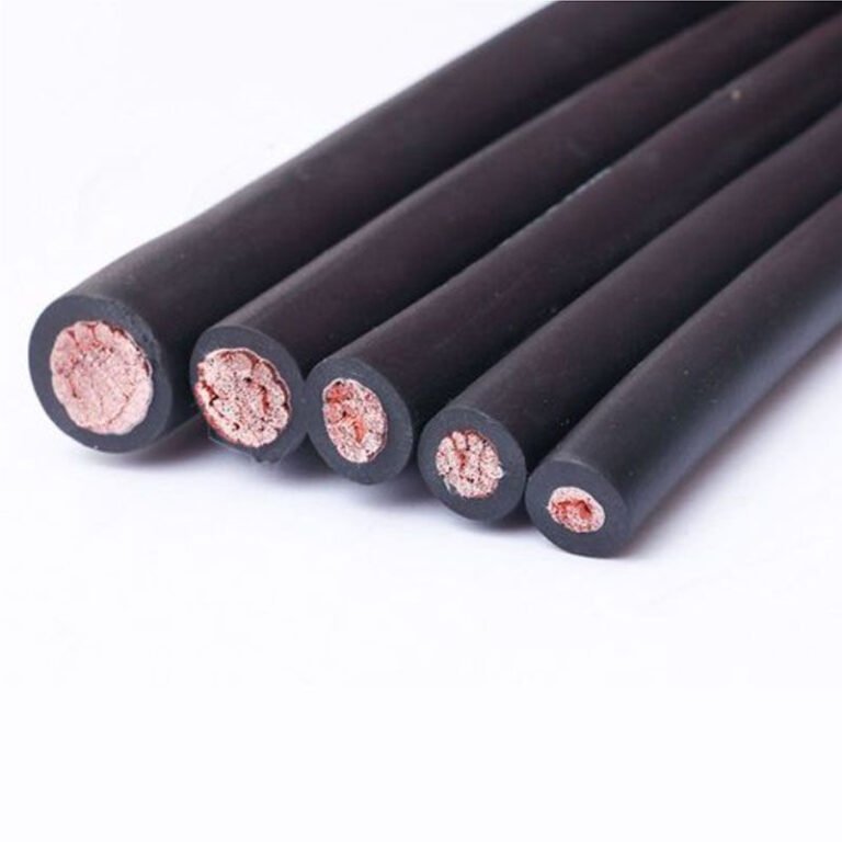
Specify the wrong cable type on a procurement order — it happens more than most engineers admit — and you can trigger a cascade that runs from installation rejection on-site, to re-pulling conductors through conduit that was never sized for the replacement, to transformer derating, to unplanned downtime that dwarfs the original cable cost several times over. The specification error is usually small and upstream. The consequence lands hard and downstream.
The three fundamental types of cable are power cables, control cables, and communication cables. Power cables carry electrical energy from source to load and are rated by voltage class — low-voltage (up to 1 kV), medium-voltage (1–35 kV), and high-voltage (above 35 kV). Control cables transmit switching signals and instrumentation data within industrial systems, typically operating below 600 V. Communication cables carry data, audio, and signal traffic, and are defined primarily by frequency bandwidth and transmission medium rather than voltage.
What makes this classification genuinely useful — rather than just textbook taxonomy — is that each type imposes completely different demands on insulation chemistry, conductor geometry, shielding architecture, and installation method. A plant that treats these three families as interchangeable is one failed inspection or arc flash incident away from learning why they aren’t. The global cable market sat at roughly USD 225 billion in 2023 and is tracking toward USD 300 billion by 2030, driven substantially by grid expansion and industrial automation — which means procurement volumes are rising fast, and so is the cost of getting the selection wrong.
Power Cables: Construction Layers, Voltage Classes, and Load-Carrying Capacity Explained
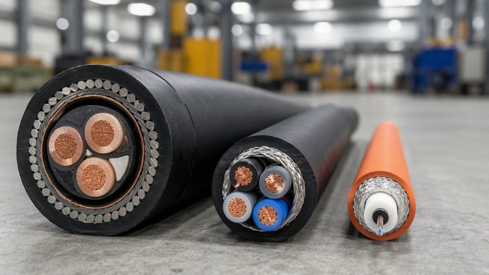
Power cables exist to move energy — from a substation busbar to a wind turbine transformer, from a utility feeder to an industrial motor control center. That sounds simple, but the engineering packed into a single cross-section is anything but. Getting the construction wrong costs real money: undersized conductors overheat, wrong insulation fails under transient overvoltages, and missing armor gets crushed during direct burial. Understanding the layers and how they scale with voltage class is the starting point for every competent procurement decision.
The Four Structural Layers and What Each One Actually Does
A power cable is essentially four concentric systems working together. The conductor — stranded copper or aluminum — carries the current. Surrounding it is the primary insulation, which blocks the electric field and prevents flashover; common materials are XLPE (cross-linked polyethylene), EPR (ethylene propylene rubber), and PVC for lower-voltage, lower-cost applications. Outside the insulation sits the metallic screen or armor layer: steel wire armor (SWA), aluminum wire armor (AWA), or a wire braid, depending on whether the primary concern is mechanical protection, fault current return, or both. The outer sheath — PVC, LSZH (low-smoke zero-halogen), or HDPE for direct burial — closes the assembly and takes the environmental abuse.
Each layer’s thickness and material grade escalates with voltage class. That’s the core scaling logic you need to internalize.
Voltage Classes: Where the Real Engineering Differences Live
Low voltage (LV) cables operate up to 1 kV and represent the largest share of global cable volume — roughly 55–60% of meters shipped annually. Insulation for LV is typically 0.6–1 mm thick PVC or XLPE. Cross-sections run from 1.5 mm² for lighting circuits up to 630 mm² or larger for main feeder runs; 2,500 mm² conductors exist for utility-grade busbar replacement applications, though those are specialist territory.
Medium voltage (MV) covers 1–35 kV. Here, XLPE largely displaces PVC because dielectric losses and thermal aging become real constraints. Insulation thickness in this range can run 3.4 mm at 6 kV up to 12–16 mm at 33 kV depending on the specific standard and conductor size. Semiconducting screens appear above roughly 3.6 kV — without them, electric field concentration at the conductor surface causes treeing failures within a few years.
High voltage (HV) runs from 35 kV to 220 kV. Underground HV cable installation costs typically fall between USD 1 million and USD 4 million per kilometer; that range depends heavily on voltage class, trench conditions, and whether you’re using fluid-cooled or XLPE insulated designs. At this level, factory acceptance testing documentation is not optional — it’s the difference between getting onto a tender shortlist and being disqualified before evaluation.
Extra-high voltage (EHV) above 220 kV is a narrow, highly specialized segment: transmission backbone, offshore interconnectors, large-scale HVDC links.
Copper Versus Aluminum: The Procurement Calculus
Copper carries roughly 58 MS/m conductivity against aluminum’s 35 MS/m. In practical terms, an aluminum conductor needs to be approximately one size class larger to carry the same current as copper. That offsets the weight advantage somewhat — aluminum is about one-third the density of copper — but aluminum cable typically still costs 40–60% less per kilogram of conductor, and on a long infrastructure run that spread compounds fast.
The complication is termination. Aluminum oxidizes quickly and requires bi-metal lugs, antioxidant compound, and more careful torque control during jointing. Skipping those steps causes high-resistance connections that arc over months, not years. For industrial plants with lots of termination points and maintenance staff who may not have aluminum jointing experience, copper often wins on total lifecycle cost even when the raw material cost favors aluminum.
Application Sectors and Standards Compliance
Power cables serve utility grid distribution, renewable energy export (wind farm 33 kV array cables, solar DC string and AC collection cables), heavy industrial plants, railway electrification systems, and offshore platforms including floating production units where armoring and sheath chemistry need to resist both mechanical stress and continuous hydrocarbon exposure.
The governing standards framework is IEC 60502 for LV and MV cables, IEC 60840 for HV, and IEC 62067 for EHV. Conductor construction follows IEC 60228 internationally and ASTM B8 in North American-spec projects. UL 44 applies to thermoset-insulated wire in U.S. installations. Third-party type test reports to these standards — not just factory declarations — are what sophisticated project engineers ask for first. If a supplier can’t produce witnessed FAT data and a traceable type test certificate from an accredited lab, that’s a procurement red flag regardless of price.
Aluminum conductors typically cost 40–60% less than copper conductors by weight for equivalent cable construction.True
London Metal Exchange spot pricing historically places aluminum at roughly one-quarter to one-fifth the price per tonne of copper, though the exact percentage difference in finished cable cost depends on stranding complexity, market timing, and conductor cross-section — the 40–60% range is a reasonable working estimate for large procurement runs.
Control Cables: Signal Integrity, Multi-Core Configurations, and Industrial Automation Roles
Control cables do one thing power cables don’t have to: they keep a signal clean. Where a power cable’s job is moving energy — kilowatts, sometimes megawatts — a control cable’s job is moving intent. A 4–20 mA loop signal from a pressure transmitter to a DCS input card, a discrete 24 V DC command from a PLC output to a solenoid valve, a feedback pulse from a proximity sensor to a motor drive. The current involved is negligible. The conductor cross-section is small. What actually matters, and what differentiates a well-specified control cable from an inadequate one, is signal fidelity under electrical noise.
Voltage ratings for control cables typically fall in the 300/500 V or 450/750 V range (AC or DC), which is well below the thresholds that drive power cable insulation design. Current is rarely more than a few amps per core, often fractions of an amp. Ampacity is essentially irrelevant as a selection criterion. Engineers who treat control cable selection like a scaled-down version of power cable selection — focusing on conductor size and voltage rating and stopping there — tend to find out later, usually during commissioning, that their analog loops are riding on a noise floor too high to be useful.
Multi-Core Configurations and Shielding Architecture
The range of core counts available in a production control cable is genuinely wide: 2-core pairs through 61 cores or beyond, depending on application. A simple machine interlock circuit might run on a 4-core cable. A large DCS marshalling cabinet connecting to a remote I/O rack might require 37 or 61 cores, organized as individually shielded pairs plus an overall collective shield. Getting that wrong — running individually shielded pairs when the spec called for collectively shielded, or omitting pair twisting in an analog loop application — is the kind of mistake that generates mysterious process fluctuations that take weeks to trace back to the cable.
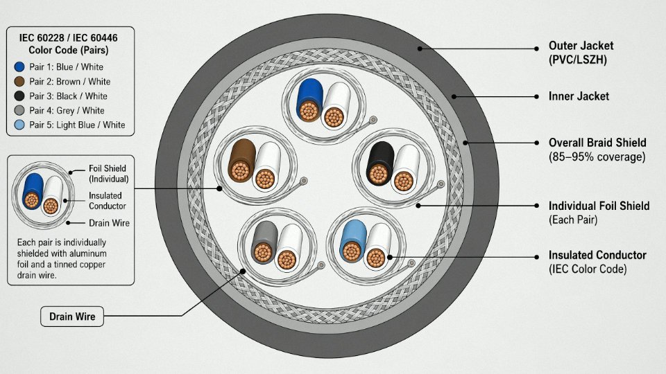
Pair twisting matters because it directly determines how well the cable rejects common-mode interference. The twist pitch — how tightly the pairs are twisted — affects cross-talk attenuation between adjacent pairs. Shielding options compound this: foil shields (aluminum-polyester laminate) are lightweight and effective against high-frequency interference; braided shields handle lower-frequency noise better and offer superior mechanical coverage, typically 85–95%; combined foil-plus-braid constructions are used in petrochemical and heavy industrial environments where both frequency ranges are a concern. Each shielded variant should include a drain wire — usually a bare or tinned copper conductor running alongside the shield — for grounding. Ground the drain at one end only. Grounding both ends creates a loop, and that loop will pick up exactly the kind of low-frequency magnetic interference you were trying to eliminate.
Construction Details That Separate Control from Power Cable
Conductor cross-sections in control cables run from roughly 0.5 mm² up to about 6 mm², with 0.75 mm², 1.0 mm², and 1.5 mm² covering the majority of industrial automation applications. Insulation walls are thinner than power cable equivalents — this is deliberate and correct, not a quality compromise. Cores are color-coded to IEC 60446 or to customer-specified schemes, which matters during termination when a technician is working through 37 cores in a cramped panel. A consistent, standards-compliant color scheme prevents wiring errors; a non-standard or poorly documented scheme creates maintenance problems that accumulate over the plant’s lifetime.
IEC 60446 color coding requirements for control cable conductors reduce termination errors during installation and maintenance.True
IEC 60446 specifies conductor identification methods including color coding, which is widely adopted in control cable manufacturing to ensure consistent, recognizable wiring at panels and terminals — a standard practice confirmed by industrial wiring guidelines.
Relevant standards for conductor construction include IEC 60228 (conductor classes), IEC 60227 and IEC 60245 (insulated cables for general and heat-resistant applications respectively), and EN 50525 for flexible control cable used in machine tool and automation contexts. For North American-export projects or machinery built to US standards, NFPA 79 governs control cable requirements for industrial machinery. Jinda’s quality management system is structured to produce against these frameworks simultaneously, which matters practically when a procurement manager is sourcing a single cable specification that needs to satisfy both a European main contractor and a Middle Eastern end-user with their own compliance requirements.
Where Control Cable Selection Gets Genuinely Difficult
Standard PVC-sheathed control cable handles most building automation and light industrial use without drama. The harder calls come in three environments.
Petrochemical DCS systems expose cables to hydrocarbon vapors, cleaning solvents, and process fluids. Here the outer sheath needs to be oil-resistant — usually an LSZH compound or a specialized PVC formulation — and the cable often needs to meet IEC 60332 flame-retardancy requirements because of the fire risk classification of the installation zone. Get the sheath chemistry wrong and you’re looking at jacket swelling or cracking within a year or two, which in a live plant means a cable replacement job under operating conditions. Nobody wants that job.
Steel mill environments are a different problem: radiated heat from furnaces and ladles can push ambient temperatures well above what standard 70°C-rated PVC insulation handles. XLPE insulation raises the continuous operating limit to roughly 90°C; silicone insulation pushes that to 180°C or beyond, depending on compound grade. The tradeoff with silicone is mechanical fragility — it doesn’t handle abrasion or repeated flexing as well as XLPE — so in high-temperature zones with fixed routing, silicone is usually the right call, but in high-temperature zones where the cable also moves, the answer depends on the specific installation geometry.
Mining applications add the flame-retardant requirement in its strictest form, often IEC 60332-3 (grouped cable flame spread), plus sometimes anti-static jacket properties depending on the mining category. In my experience, the projects where control cable specification gets the most scrutiny at the engineering stage are exactly these three sectors — and they’re also the projects where a cable substitution during construction is most expensive and most disruptive.
Communication and Signal Cables: Data Transmission, Bandwidth Demands, and Network Infrastructure
The third cable type is where electrical engineering and IT infrastructure collide, and it’s the category most likely to generate specification disputes on a job site. Power cables move energy. Control cables carry commands. Communication and signal cables move information — and the tolerance for getting the selection wrong is tighter than most procurement teams expect.
The Four Sub-Families and What Separates Them
Twisted-pair copper data cables are what most people picture first: Cat5e, Cat6, Cat6A, Cat7, Cat8. The bandwidth progression runs from 100 MHz at Cat5e up to 2,000 MHz at Cat8, and the practical throughput ceiling scales accordingly. Cat6A handles 10 Gbps over a full 100 m horizontal run, which covers most structured cabling layouts in commercial buildings and light industrial facilities. Cat8 pushes 40 Gbps but only over roughly 30 m — so it’s a data center interconnect cable, not a floor-to-floor backbone option. That distance limitation catches people out when they’re specifying server room layouts under schedule pressure.
Coaxial cables — the RG series — still show up regularly in CCTV systems, RF distribution, and older SCADA communication links. RG-6 and RG-59 dominate CCTV; RG-11 runs longer distances at lower signal loss where trunk cabling needs it. They’re not going away in legacy retrofit work anytime soon.
Telephone and multipair cables deserve a mention even though voice-over-IP has displaced a lot of traditional telephony. In large process plants and utility substations, multipair cables still serve as the physical layer for SCADA remote terminal units, intercom systems, and alarm circuits — applications where the priority is reliability over bandwidth. Twenty-five pair, 50 pair, or 100 pair configurations in a single sheath keep conduit counts manageable.
Fiber optic cables are where the real growth is. Single-mode OS2 fiber operates at 1310 nm and 1550 nm wavelengths, with attenuation at or below 0.4 dB/km — meaning a signal can travel well past 10 km without any active amplification in between. That matters enormously for campus networks, wind farm collector systems, and smart grid distribution automation, where copper simply cannot bridge the distances without repeaters. Multimode OM3 and OM4 fibers cover shorter runs, typically up to 300–400 m at 10 Gbps depending on the transceiver, and they’re the standard choice for within-building vertical risers and data center structured cabling where cost per port matters.
OS2 single-mode fiber achieves attenuation ≤ 0.4 dB/km at 1310 nm per IEC 60794 and ITU-T G.652 standards, supporting transmission distances exceeding 10 km without amplification.True
This is a well-established fiber optic performance parameter defined in ITU-T G.652 (the standard for single-mode optical fiber) and consistent with IEC 60794 test requirements. The 0.4 dB/km figure is the maximum specified attenuation, and modern OS2 fiber routinely performs better than this in practice.
Shielding Architecture in Mixed-Use Cable Trays
This is where field experience overrides catalog selection. An unshielded twisted pair (UTP) cable is perfectly adequate in an office LAN environment with clean power and no heavy inductive sources nearby. Put that same UTP in an industrial cable tray running parallel to 400 V motor feeders for 20 or 30 meters, and you will see noise-induced bit errors that no amount of switch configuration will fix.
IEC 61156 and ISO/IEC 11801 both address separation distances between power and data cables, but in practice, plants rarely have the physical space to maintain those separations rigorously. The engineering answer is shielded twisted pair — STP, SFTP, or foil-screened F/UTP designs — which provide the electromagnetic immunity the application actually requires rather than the immunity the office-grade catalog specification assumed. Getting this wrong means intermittent network faults that look like switch failures or firmware bugs and waste weeks of maintenance time before anyone pulls the cable tray cover off to look.
Hybrid Cables: Real Efficiency Gains, Real Engineering Constraints
Wind turbine nacelle wiring is the clearest example of where hybrid cable construction earns its place. A single jacket combining power cores and fiber optic elements eliminates a separate cable pull, reduces conduit fill, and simplifies installation sequencing on a structure where access is genuinely difficult and expensive. Industrial IoT sensor networks and smart grid automation projects are pushing the same direction — hybrid power-plus-fiber constructions that cut installation labor by consolidating runs.
The tradeoffs are real though. Bend radius management becomes more complex when power conductors and optical fibers share a jacket, because the thermal expansion of copper under load and the mechanical sensitivity of fiber don’t coexist without careful design. Thermal management is the other constraint: power cores generate heat, and elevated temperatures affect fiber transmission characteristics and jacket integrity over time. These hybrid cables need to be specified with both the electrical load profile and the fiber performance budget in mind simultaneously — something that occasionally gets missed when two different engineering disciplines are working in parallel on the same project.
Standards Compliance and Site Acceptance
TIA-568 governs structured cabling in North America; ISO/IEC 11801 covers international installations; IEC 60794 defines fiber optic cable test methods; ITU-T G.652 sets the benchmark for single-mode fiber performance. For smart city, data center, and infrastructure projects, system integrators routinely need manufacturer test certificates and compliance documentation to pass site acceptance tests and satisfy the authority having jurisdiction. This is not a paperwork formality — it directly affects commissioning timelines and sometimes triggers contract penalty clauses when documentation is incomplete or ambiguous. Having a cable supplier who can produce traceable, standard-referenced test data at delivery rather than weeks afterward is worth factoring into supplier selection before the project starts.
Side-by-Side Technical Comparison: Choosing the Right Cable Type for Your Specific Application
Before any tender document gets written, someone on the engineering team needs to answer a deceptively simple question: which cable type, exactly, and to what specification? Get that wrong and you’re looking at EMI-induced nuisance trips, a failed FAT, or — in the worst case — a thermal failure inside a buried duct that costs more to excavate than the original cable did to buy.
The table below consolidates the key selection attributes across all three cable types. Use it as a starting checklist, not a final specification — real projects always layer on site-specific derating and environmental factors afterward.
| Attribute | Power Cable | Control Cable | Communication / Signal Cable |
|---|---|---|---|
| Primary function | Carry load current to equipment | Transmit switching and analog/digital control signals | Carry data, voice, video, network traffic |
| Typical voltage range | 0.6/1 kV up to 500 kV (HV transmission) | Usually 300/500 V or 450/750 V | Typically below 100 V; structured cabling essentially voltage-free |
| Typical current range | 10 A up to several thousand A | Milliamps to low single-digit amps | Milliamps or below (signal level) |
| Conductor cross-section | 1.5 mm² up to 2,500 mm² (varies with voltage class and installation method) | 0.5 mm² to 6 mm², most commonly 1–2.5 mm² | 22–26 AWG for copper data cables; glass fiber for optical |
| Insulation system | XLPE, EPR, or PVC depending on voltage class and thermal rating | PVC or LSZH; oil-resistant PVC or TPE in process plants | PE, FEP, or LSZH jacket; OS1/OS2 optical fiber for fiber runs |
| Shielding requirement | Generally not shielded; SWA or AWA for mechanical protection | Often required — individual pair or overall foil/braid screen | Always present in structured cabling; foil or braid by category |
| Applicable standards | IEC 60502, IEC 60840, ICEA S-93-639 | IEC 60227, IEC 60245, EN 50525 | ISO/IEC 11801, TIA-568, IEC 60793/60794 for fiber |
| Typical cost tier | Moderate to high (copper content dominant) | Low to moderate | Low (copper Cat cable) to high (singlemode fiber infrastructure) |
Three Project Scenarios That Illustrate the Selection Logic
Scenario 1 — 33 kV underground feeder to an industrial park. The cable runs approximately 2.4 km from a utility substation through direct-buried conduit under a paved road. Specified correctly: 33 kV XLPE-insulated, copper conductor, double steel wire armored (DSWA), with an LSZH outer sheath where the route passes under a building. At this voltage class and burial condition, anything less than SWA is a mechanical liability; anything less than XLPE insulation is a thermal compromise given the continuous load. Underground HV feeder installations at this voltage class typically run USD 1–3 million per kilometer depending on soil conditions, crossing complexity, and local civil costs — so a cable specification error is not a rounding problem.
Scenario 2 — PLC-controlled conveyor in a food processing plant. The environment involves daily washdowns, incidental contact with cleaning solvents, and motor VFD drives running nearby. The right cable: multi-core (typically 4–12 core), 1.5 mm² conductors, overall braided shield, oil-resistant and moisture-resistant outer jacket, rated to at least 75 °C continuous. A standard unshielded PVC control cable in this environment will absorb moisture at termination points within months and pick up enough VFD switching noise to generate spurious signals on 4–20 mA analog inputs — which in a food line means unexpected conveyor stops and, in some configurations, a safety interlock failure.
Scenario 3 — Smart building backbone. A mid-rise commercial building needs to support IP cameras at 1 Gbps PoE+ and a 10 GbE LAN simultaneously on the horizontal cabling, with OS2 singlemode fiber on the riser for inter-floor backbone. Cat6A (F/UTP or U/FTP depending on whether alien crosstalk is a concern in high-density trays) handles the horizontal runs up to 100 m. OS2 fiber handles the backbone — attenuation typically under 0.4 dB/km at 1310 nm, supporting distances far beyond what copper could manage. Using Cat5e here is a cost-optimization that fails within two years as camera resolution increases.
Where Projects Go Wrong
The three misapplication mistakes I see most often in field audits are consistent enough that they’re almost predictable.
Using a standard power cable instead of a screened control cable on PLC I/O runs is the most common. The symptom is intermittent false trips — hard to diagnose because they correlate with motor starts, not with the cable itself. By the time someone traces it to EMI coupling, the production records show dozens of unexplained stops.
Running unshielded data cable in a shared cable tray with 400 V power cables violates ISO/IEC 11801 separation requirements outright. The installers often know this but cut corners when tray space is tight. The result is elevated alien crosstalk and link failures under load, most visible during peak LAN utilization.
Under-rating the voltage class on power cables in renovation projects is the genuinely dangerous one. When original design documentation is lost — and it often is in buildings more than 20 years old — the temptation is to match the physical size of the existing cable rather than verify the voltage class. A 0.6/1 kV cable substituted on a circuit that was originally specified for 3.6/6 kV service will pass initial continuity testing and then fail under operating stress.
How Ambient Conditions Drive the Final Specification
Selecting the cable type is step one. Selecting the correct variant within that type depends on installation and operating environment — and this is where IEC 60364-5-52 becomes the working document rather than background reading.
Continuous operating temperature determines insulation choice: XLPE handles 90 °C conductor temperature versus 70 °C for standard PVC, which matters significantly in tightly bunched conduit runs with high load factors. UV exposure rules out standard PVC outer sheaths in any outdoor or rooftop installation unless UV-stabilized compound is specified — PVC sheaths not rated for UV will chalk and crack within two to three years in high-irradiance climates. Chemical splash environments require jacket materials tested against the specific chemicals present, not just “chemical resistant” as a marketing claim.
Fire risk classification under IEC 60332 (categories A through D, covering single-cable through large-scale installation flame propagation tests) directly affects which cable variants are permissible in escape routes, tunnels, and high-occupancy buildings. IEC 60332-3-22 (Category A) imposes the most demanding flame propagation limits and is increasingly specified by default in public infrastructure projects even where local codes would technically permit less.
IEC 60332 flame propagation test categories apply to installed cable bundles, not just individual cables — a cable passing IEC 60332-1 as a single cable may still fail IEC 60332-3-22 when installed in a bundle of the same type.True
IEC 60332-1 and -2 test single cables or small groups; IEC 60332-3 series tests bundles in a ladder configuration with a defined total halogen-free or PVC-jacketed cable volume. Bundle behavior depends on jacket material volume and installation density, not just individual cable performance.
Jinda’s Technical Support for Complex Cable Selections
For projects where the standard selection tables produce ambiguous results — high-ambient underground installations, mixed-use cable trays where power and instrumentation share limited space, or specifications referencing multiple overlapping international standards — Jinda’s engineering team provides direct consultation on cable selection, derating calculations, and custom cable design for non-standard cross-sections or jacket compounds. That kind of application-level support matters most in international projects where the local standards, the IEC baseline, and the end-client specification all say slightly different things.
Installation Best Practices That Protect Cable Performance Across All Three Types
Getting the cable selection right is only half the job. A correctly specified 240 mm² XLPE power cable, a well-shielded multi-core control cable, or a low-loss fiber optic trunk can all be rendered useless — or genuinely dangerous — by poor installation practice. In my experience, termination failures and bending radius violations account for more premature cable failures in the field than material defects ever do.
Bending Radius: The Limit Engineers Most Frequently Ignore
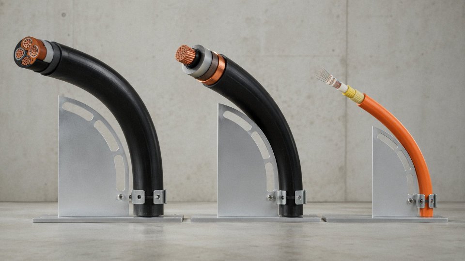
Every cable family has a minimum bending radius, and it is not a conservative safety margin — it is the point below which physical damage begins. For LV power cables, the working rule during pulling is 12–15× the overall cable diameter, relaxing to 8–10× once the cable is at rest and secured. Armored MV cables are stiffer and less forgiving; 15–20× overall diameter is the practical floor, and that figure rises further for cables with thick wire armor or large conductor cross-sections. Violating these limits causes insulation to crack at the bend apex, initiates conductor fatigue at stranded wire interfaces, and — in XLPE cables — can create mechanical stress points that propagate into partial discharge sites over time.
Fiber optic cables are the most sensitive of the three. The commonly cited 10× outer diameter minimum must be respected during both installation and final routing. Micro-bending loss from a single overtight cable tie or a sharp tray edge can add 0.5–1.5 dB of attenuation to a link that was designed to budget for 0.3 dB total. That loss is irreversible without re-pulling or re-splicing.
Pulling Tension and Sidewall Bearing Pressure in Duct Installations
Underground duct bank and direct-buried installations introduce mechanical stresses that surface tray work does not. For copper conductor cables, the accepted pulling tension limit sits at roughly 50 N/mm² of conductor cross-section — so a 150 mm² copper cable can take around 7,500 N of pulling force before the conductor begins to stretch and insulation adhesion is compromised. Aluminum conductor cables are rated lower, typically around 40 N/mm², partly because aluminum work-hardens differently under tension. These are not worst-case theoretical numbers; exceeding them is a documented leading cause of insulation failure that shows up 2–5 years into service rather than immediately, which makes the root cause hard to trace.
Sidewall bearing pressure at duct bends is a separate concern. A cable pulled around a 90° bend in a PVC conduit concentrates lateral load at that point. Calculate it, don’t estimate it by eye.
Segregation in Multi-Cable Tray Layouts
IEC 61537 and most national wiring codes require a minimum 200 mm separation between power cables and signal or data cables running in parallel — and that figure climbs to 600 mm or more when the power feeder is a high-current MV circuit. In large industrial projects, this requirement directly drives tray quantity, support steel weight, and ceiling-space allocation. The practical approach is separate physical trays with solid dividers rather than relying on distance alone, particularly where instrumentation cables for 4–20 mA loops share the same cable route as variable-frequency drive outputs, which are notoriously noisy.
Thermal De-Rating: A Worked Example Worth Keeping
Ampacity tables assume specific installation conditions, and real installations rarely match them. A 240 mm² copper XLPE cable — rated at roughly 432 A in free air at 30°C ambient — will de-rate to somewhere around 285–295 A when installed as one of six cables in a duct bank at 40°C ambient soil temperature, applying the grouping and temperature correction factors from IEC 60364-5-52. That is a 32–34% reduction. Ignore that de-rating and you are running the cable above its thermal design point continuously, which degrades XLPE faster than any other single operational factor.
A 240 mm² XLPE copper cable rated at ~432 A in free air can de-rate to approximately 285–295 A when grouped with five other cables in a duct bank at 40°C ambient, per IEC 60364-5-52 correction factors.True
IEC 60364-5-52 provides grouping reduction factors (typically 0.57–0.62 for six cables) and temperature correction factors for elevated ambient conditions; applying both to a free-air rating of approximately 432 A yields a realistic de-rated value in the 285–300 A range depending on soil thermal resistivity and specific installation geometry.
Termination Quality: Where Most Failures Actually Originate
If there is one place to spend disproportionate attention on a cable project, it is terminations and joints. For MV power cables, stress cone geometry at the termination point is critical — a poorly seated heat-shrink or cold-shrink stress cone leaves an air gap at the insulation screen cutback, which becomes a partial discharge initiation site. Compression lug torque matters too; under-torqued lugs create resistance hot spots, over-torqued lugs crush conductor strands and reduce the effective cross-section. Both failure modes show up in thermal imaging surveys years later.
For control cables, the drain wire must be grounded at one end only — grounding both ends creates a circulating current loop that introduces exactly the noise the shield was meant to exclude. Shield continuity testing before commissioning is a five-minute check that prevents days of troubleshooting.
For fiber optic terminations, end-face cleanliness is not optional. The pass/fail criterion under TIA-568 is ≤ 0.3 dB insertion loss per mated connector pair. A dirty or poorly polished end face can add 0.5–2.0 dB per connection, and in a long optical link with multiple joints, that budget overrun kills the link entirely. Inspect every end face with a fiber microscope before mating. Every one.
Global Standards Compliance and How Manufacturers Like Jinda Support International Project Documentation
Every cable project that crosses a national border immediately runs into a compliance matrix that can derail procurement timelines faster than almost any other technical issue. A single wind farm or data center project in Southeast Asia might require IEC type test evidence for the medium-voltage feeders, CPR Euroclass documentation for any cables routed inside occupied buildings, and a project-specific end-user engineering standard on top of that. Getting this wrong at tender stage means rejection, re-testing, and in the worst case, re-manufacturing.
The Major Standards Bodies and Why No Single Framework Covers Everything
IEC publications form the backbone of cable specification globally. IEC 60228 governs conductor classes — the difference between Class 1 solid, Class 2 stranded, and Class 5 flexible conductors is not academic; specifying the wrong class in a cable schedule causes real problems at termination. IEC 60502 covers extruded insulation power cables up to 30 kV, while IEC 60840 and 62067 step up to high-voltage and extra-high-voltage systems respectively. For fire behavior, IEC 60332 series (single cable, bunched cables) and IEC 60794 for fiber optic cables complete the core set most project engineers encounter.
CENELEC harmonizes IEC publications into EN standards for the European market — EN 60332 is effectively IEC 60332 with European adoption markings, but the Construction Products Regulation (CPR) adds an entirely separate layer that has no direct IEC equivalent. In North America, UL 44 (thermoset-insulated), UL 83 (thermoplastic-insulated), and UL 1072 (medium-voltage) dominate utility and building applications, with CSA standards covering Canadian projects. Australia and New Zealand run AS/NZS 5000 series cables, which share IEC DNA but differ in conductor sizing conventions and sheath color codes in ways that catch exporters out regularly.
Then there are major end-user standards. Saudi Aramco’s SAES-P-104 is a good example of how a single large project owner can impose requirements that exceed any national standard — specifying conductor sizes, insulation systems, sheath materials, and drum marking in ways that require a manufacturer to produce a dedicated product variant rather than pull from standard stock.
CPR Euroclasses: Fire Performance Is More Than a Flame Test
The CPR Euroclas system — Aca through Fca — is frequently misunderstood as a simple fire rating. It actually combines five performance characteristics: flame spread, heat release rate, smoke production, acidity of combustion gases, and flaming droplet behavior. A cable classified Cca-s1,d1,a1 has passed stringent limits on all five dimensions. Dca is the minimum class required in many commercial and public buildings across the EU; Cca applies to higher-risk infrastructure like tunnels, hospitals, and rail stations.
Jinda’s LSZH cable lines are specifically formulated and tested to achieve Cca and Dca classifications. The compound selection — low-smoke zero-halogen thermoplastic or thermoset sheath compounds — is not interchangeable with standard PVC formulations, and the CPR Declaration of Performance (DoP) that accompanies each compliant cable is a legally binding document under EU Regulation 305/2011. Selling a cable into Germany or France without a valid DoP from a notified body is not a compliance shortcut; it’s a liability.
Jinda's LSZH cable products are tested and certified to CPR Euroclasses Cca and Dca through accredited third-party testing.True
CPR certification requires testing by an EU-notified body and issuance of a Declaration of Performance — Jinda maintains these certifications to support European market supply and EPC contractor submittals.
What Jinda’s In-House Test Infrastructure Actually Means for Your Submittal Package
A manufacturer’s quality system matters in practice because type test reports and factory test reports are the documents that get scrutinized during project technical review. Jinda operates an in-house high-voltage test laboratory with capability up to 220 kV — covering partial discharge testing, AC withstand, and impulse voltage for MV and HV cables. Conductor resistance, insulation resistance, and mechanical tests (tensile strength, elongation at break, cold bend) run on every production batch.
The distinction between a Type Test Report (TTR) and a Factory Test Report (FTR) matters to EPC contractors. TTRs demonstrate that a cable design has been validated against the full IEC or EN test schedule, ideally at an accredited third-party laboratory — KEMA (now part of DNV), CESI in Italy, and CSA Group are the names that appear on the short list for most project specifications. FTRs confirm that each production drum meets the design’s verified parameters. Bundling both into a project technical submittal, along with a cable schedule compliance matrix and REACH/RoHS declarations, is standard practice for international EPC procurement. Jinda’s documentation team manages this for large multi-shipment orders, including drum-by-drum traceability and mill test certificates that map back to specific production batches — which matters more than people realize when a project involves 18 months of phased deliveries and the end-user’s inspector arrives on site with a drum number to verify.
Production Geography, Port Connectivity, and INCOTERMS
Jinda’s five production bases across China handle different product specializations — high-voltage and extra-high-voltage cables, low-voltage building wire, industrial control cables, and specialty cables each benefit from dedicated manufacturing environments rather than running everything on shared lines. Logistics connectivity is practical: Qingdao and Tianjin serve northern routes efficiently for Middle Eastern and European shipments, while Shanghai handles high-volume Southeast Asian and African orders with container slot availability that matters on time-sensitive projects.
INCOTERMS configuration affects documentation obligations and insurance liability in ways procurement teams sometimes underestimate. FOB suits buyers who control their freight forwarder and want to consolidate shipments; CIF shifts marine insurance to the seller and simplifies the buyer’s logistics for single-origin orders; DAP is increasingly requested for projects in markets where port clearance is complicated and the buyer wants the manufacturer to absorb that risk. Jinda has delivered under all three configurations to customers across the Middle East, Africa, Southeast Asia, and Europe, which means the commercial and customs documentation infrastructure is already in place — not something being built project by project.
Procurement Strategy for Bulk Cable Orders: Lead Times, Drum Quantities, and Supply Chain Risk Management
Getting the technical specification right is only half the battle. The other half — the one that actually determines whether a project finishes on schedule — is procurement timing, schedule structure, and supply chain architecture. Engineers who’ve lived through a cable shortage on a live construction site know this viscerally.
What Actually Drives Lead Times
Lead time is not a fixed number a manufacturer pulls from a shelf. It’s a function of at least four compounding variables.
Conductor material availability is the most volatile. LME copper prices fluctuate by 15–30% within a single calendar year in active markets, and when prices spike, fabricators across the supply chain defer purchases simultaneously — which tightens rod and wire rod supply exactly when demand is highest. Large cross-section aluminum conductors (240 mm² and above) carry their own lead time risk during infrastructure boom cycles; aluminum rod supply is geographically concentrated and less fungible than it looks on a datasheet.
Insulation compound production adds another layer. XLPE compound for medium- and high-voltage cables is not stocked in bulk at most plants; it’s manufactured or ordered against confirmed production runs. Armor wire, steel tape, and bedding compounds each have their own procurement queues.
Factory queue depth is the variable buyers most consistently underestimate. A manufacturer running at 85%+ capacity utilization — which is typical during infrastructure upswings — will quote longer lead times regardless of material availability. Understanding where a supplier sits in their production cycle before committing to a project schedule is basic due diligence that surprisingly few procurement teams perform.
Realistic ranges, stated plainly: standard LV stock constructions (NYY, XLPE/SWA up to 4-core 95 mm²) can often ship in 4–6 weeks from a well-stocked facility. Engineered HV underground cable projects — 66 kV and above, with custom insulation wall thicknesses and specialized armoring — routinely require 16–24 weeks, sometimes longer for submarine designs with integrated optical fiber elements. The specific figure depends on voltage class, whether compound needs to be specially formulated, and current factory loading.
Structuring a Cable Schedule That Actually Works
A poorly organized cable schedule generates requotation cycles, substitution errors, and batch fragmentation — all of which add cost and delay. The discipline that eliminates most of this pain is simple: organize first by cable type (power, control, communication), then by voltage class within each type, then by conductor cross-section and core count in ascending order.
This structure lets the manufacturer identify production batches where similar constructions can run consecutively on the same extrusion or stranding line, reducing setup changeovers and genuinely lowering unit cost on large orders. A project schedule that mixes 0.6/1 kV power cable with 11 kV feeders and 24-core fiber optic cable in a single undifferentiated list will cost the buyer more — sometimes 4–8% more on total cable value — simply due to production inefficiency that the manufacturer has to price in.
Preventing substitution errors matters just as much. When a schedule is ambiguous about conductor material (copper versus aluminum) or insulation system (PVC versus XLPE) at similar voltage ratings, manufacturers making pricing assumptions will sometimes quote the cheaper option without flagging it explicitly. That mismatch between what was quoted and what the project actually requires surfaces at delivery, not before.
Drum Length Optimization: The Cost Lever Most Buyers Ignore
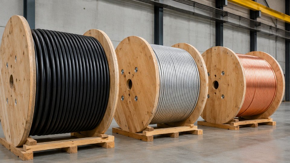
Standard drum lengths for LV power cable typically run 500 m to 1,000 m. These are production-convenient lengths, not project-convenient lengths. On a complex industrial site — a petrochemical facility, a large data center fitout, a port terminal — installed run lengths rarely align with standard drums. The result is waste cable, which on complex sites commonly runs 3–8% of total cable purchased, plus the cost of joints wherever a drum runs short mid-run.
Joints are not free. A properly executed LV cable joint with correct materials, a competent jointer, and proper documentation costs somewhere between USD 150 and USD 600 per joint depending on size and location — before you factor in the conduit work, schedule delay, and the inspection hold that many project owners impose on underground joints in critical circuits.
Specifying custom drum lengths matched to installed run lengths eliminates most of this. Jinda’s production configuration accommodates custom drum lengths from 100 m up to 2,000 m across its LV and MV cable ranges, which means a project procurement manager can submit a cable schedule with run-specific drum lengths and receive material that installs without waste or forced joints.
Jinda Cable accommodates custom drum lengths from 100 m to 2,000 m for LV and MV cable typesTrue
Confirmed by Jinda's manufacturing specifications across its five production bases, enabled by flexible take-up and drum-winding equipment on LV/MV extrusion lines
Risk Mitigation for Critical Infrastructure Projects
No single-source cable strategy is acceptable for a project where cable failure or non-delivery causes consequential loss. Dual-sourcing — one primary manufacturer and one qualified backup — is the minimum for EPC contractors on critical infrastructure work. The backup supplier needs to be qualified against the same technical specification before the project starts, not identified in a panic when the primary reports a delay.
Strategic pre-ordering of conductor material is underused. For large cross-section aluminum cable orders placed during a period of copper price strength, an experienced procurement manager will sometimes negotiate with the cable manufacturer to pre-purchase and warehouse aluminum rod against a confirmed order, locking material cost before the production window opens. This shifts some inventory risk to the buyer but protects against the scenario where copper prices normalize and aluminum rod demand spikes simultaneously.
Warehouse stocking agreements — where the manufacturer holds a buffer quantity of project-specific cables against a framework order — suit long-duration EPC projects well. The financial instrument that best aligns delivery milestones with payment is a letter of credit structured with milestone-based tranches: one tranche on raw material procurement confirmation, one on cable production completion, one on third-party test certification, and the balance on delivery. This protects both parties without tying up the buyer’s working capital against future deliveries.
Why Vertical Integration Changes the Supply Chain Equation
Most cable manufacturers are assemblers more than manufacturers — they buy conductor rod, insulation compound, armor wire, and sheathing material from separate suppliers, then extrude and assemble. Every inter-supplier interface is a schedule risk and a quality control gap.
Jinda’s five production bases operate an integrated model covering conductor drawing, compound production, stranding, insulation extrusion, armoring, sheathing, testing, and logistics within the same organizational structure. In practical terms, this means the production schedule for a large order is not dependent on three or four external supplier delivery confirmations running in parallel. When a project requires compressed lead time — a delayed award, a fast-track construction program — an integrated manufacturer has more levers to pull than one assembling from external components.
The QC integration argument is equally real. When the same organization draws the conductor, extrudes the insulation, and performs the finished cable test, the traceability chain is complete and internally auditable. That documentation trail — material certificates, compound batch records, process records, test reports — is exactly what international EPC contractors and project owners need for handover packages and as-built records on infrastructure projects governed by IEC, BS, or UL standards.
Emerging Cable Technologies Reshaping How All Three Cable Types Are Designed and Deployed
The three-cable framework hasn’t changed, but what’s happening inside each category is moving faster than most procurement cycles can track. HVDC, halogen-free compounds, hybrid designs, and embedded sensing are all reshaping what engineers actually specify — and what manufacturers need to be qualified to produce.
HVDC: The Fastest-Moving Segment in Power Cable Engineering
High Voltage Direct Current transmission has been around since the 1950s, but the current wave of investment is different in scale and technology. HVDC eliminates the reactive power losses that make AC transmission inefficient over distances beyond roughly 600–800 km on overhead lines, or much shorter distances underground and subsea where cable capacitance is severe. That physics argument is now driving real capital: European transmission system operators are specifying extruded 525 kV HVDC cable systems for interconnectors between countries, a voltage class that barely existed commercially a decade ago.
The insulation chemistry matters here. Conventional AC-rated XLPE cannot simply be repurposed for HVDC. Space charge accumulation in DC electric fields behaves completely differently from AC dielectric stress, and standard XLPE formulations can develop field inversion effects that accelerate insulation degradation. Qualified HVDC cable uses either mass-impregnated (MI) paper insulation — the proven technology for deep-sea cables, though expensive and slow to manufacture — or specifically compounded extruded XLPE or HPTE that has been formulated and qualification-tested for DC service. The testing protocols alone, per IEC 62895 for land cables, run to 12–18 months. Procurement managers who treat an AC-rated XLPE cable as interchangeable with an HVDC-qualified cable of the same conductor cross-section are looking at a potentially catastrophic insulation failure years down the line.
The LSZH Shift: Real Performance Trade-offs Engineers Need to Understand
Halogen-free low-smoke zero-halogen compounds are now regulatory mandatory in a growing list of jurisdictions — rolling stock in Europe under EN 45545, offshore platforms under IEC 60092-360, tunnels in most developed markets, and public buildings in an expanding set of national fire codes. The performance case is real: when PVC burns, it releases hydrogen chloride gas that is both corrosive to adjacent equipment and acutely toxic in confined spaces. LSZH compounds avoid that. The trade-off is that LSZH sheaths and insulations are stiffer at low temperatures — typically down to around -15°C to -20°C versus -40°C or better for some PVC formulations — which matters if you’re pulling cable in an unheated Nordic installation in January. Material cost runs roughly 15–30% higher than comparable PVC-sheathed cable, depending on compound supplier and order volume.
The mandate is firmest in transport and offshore. For general industrial buildings, it varies by country and sometimes by local authority interpretation. Worth checking before defaulting to LSZH on a specification just because the last project required it.
Hybrid and Composite Cables: One Jacket, Multiple Standards Problems
Bundling power cores, control pairs, and fiber optic elements into a single cable makes obvious sense for offshore wind turbines, EV charging pedestals, and articulated robot arms — you run one cable instead of three. The engineering headaches are non-trivial. Metallic conductors and optical fibers have different coefficients of thermal expansion, so a cable that looks fine at ambient temperature can induce microbending losses in the fiber when current loading heats the power conductors. Achieving a minimum bend radius that satisfies all sub-components simultaneously often forces a larger overall cable diameter than a naive calculation would suggest.
Type approval is the real procurement complication. A hybrid cable may need to satisfy IEC 60502-1 for the power element, IEC 61158 for a fieldbus pair, and IEC 60793 for the optical element — simultaneously, in the same physical construction. Getting that documentation package right takes months and requires a manufacturer with genuine multi-standard qualification capability, not just one that can screen-print multiple logos on a drum end.
Smart Cable Monitoring: Infrastructure, Not Commodity
Distributed temperature sensing using Raman backscatter on a dedicated fiber core embedded alongside power conductors lets operators see real-time thermal profiles along an entire cable route — detecting hotspots from partial burial, unexpected load increases, or soil thermal resistivity changes before they become failures. Partial discharge monitoring sensors at cable joints provide early warning of insulation degradation that would be invisible to conventional metering. Neither technology is exotic anymore; both are actively specified on high-value underground and subsea cable installations.
RFID tags at drum ends — encoding cable type, conductor cross-section, drum length, factory test results, and manufacturing date — are a simpler technology but surprisingly high-impact for asset management. A project with 40,000 meters of cable across multiple drum sizes benefits enormously from machine-readable traceability at every handoff point, from factory loading dock to final installed position.
Jinda is actively developing higher-temperature-rated XLPE compounds targeting 105°C continuous conductor temperature, alongside new aluminum alloy conductor formulations designed for improved creep resistance in sustained-load applications.True
These represent genuine active R&D directions within Jinda's product development program, aligned with industry demand for higher-ampacity and longer-service-life MV cable systems in renewable energy applications.
Jinda’s qualification testing of 35 kV XLPE MV cables to IEC 60502-2 is specifically oriented toward distributed renewable energy projects across Southeast Asia and Africa — markets where grid extension is happening fast, utility-grade specifications are tightening, and price pressure coexists with genuine technical requirements. That combination is harder to serve than either end of the spectrum alone.
Frequently Asked Questions About Cable Types, Selection, and Procurement

Can I use a power cable instead of a control cable to carry PLC signals?
No. Full stop. Power cables are built for current-carrying capacity — large conductor cross-sections, thick insulation, minimal attention to inter-core crosstalk. None of that translates to signal integrity. A PLC or DCS system running over power cable in a busy cable tray alongside 400 V motor feeders will pick up electromagnetic interference from those adjacent circuits, producing erratic relay operation, nuisance trips, and corrupted digital communications. In practice, maintenance teams often chase these faults for days before anyone thinks to pull the cable schedule and notice the wiring error.
Control cables for automation and instrumentation work need twisted-pair or twisted-trio construction, individual screen and/or collective screen, and conductor sizes typically in the 0.5–2.5 mm² range where signal levels, not thermal load, govern the choice. Specify multi-core screened control cable per IEC 60227 or IEC 60502-1, and insist the screen is properly terminated at one end only to avoid circulating ground currents — a detail that gets missed more often than it should.
What is the difference between armored and unarmored cable, and when does armoring become mandatory?
Armoring — steel wire armor (SWA) or aluminum wire armor (AWA) — adds a layer of mechanical protection against crushing loads, rodent attack, and accidental dig-in. For direct-buried power cables and cables in concrete encasement, armoring is effectively mandatory under most project specifications and is required to meet the mechanical stress categories in IEC 60364-5-52. If a backhoe strikes an unarmored cable buried at 600 mm, you are looking at a flash fault, a supply outage, and a repair excavation. An armored cable in the same scenario has a fighting chance.
Above-ground installations in cable trays or conduit inside controlled industrial facilities are a different story. Here the tray itself provides mechanical protection, and unarmored XLPE/PVC cable is perfectly legitimate — lighter, easier to terminate, and cheaper. The decision hinges on the installation environment and the wiring system category assigned at design stage per IEC 60364-5-52. IEC 60502 governs construction requirements for both armored and unarmored LV and MV power cables.
How do I calculate how much cable I need for a project?
Start from the routed length measured off cable schedule drawings — not the straight-line distance between endpoints. Apply a sag/droop allowance of roughly 3–5% for overhead runs. Add a termination tail of at least 1–2 m per cable end; on large multi-core cables, generous tails are not wasted, they save you when a termination needs to be remade. Layer on a site waste and damage factor of 3–5% for clean, well-managed routes, and up to 8–10% for congested multi-floor industrial buildings where cables get nicked, miscounted, or cut short. Always round up to the next standard drum length. Mid-run joints are a maintenance liability — if they are not pre-engineered into the design with proper joint bays and documentation, do not create them to save half a drum.
What is LSZH cable and where is it required?
LSZH (Low Smoke Zero Halogen) cable uses insulation and sheath compounds formulated to produce minimal smoke and no halogen acid gases when burning. That matters enormously in enclosed spaces: thick black smoke is a primary cause of evacuation failure in underground rail fires, and hydrogen chloride gas from burning PVC corrodes switchgear and electronics throughout a building long after the fire is suppressed.
LSZH is mandated or strongly recommended in metro and underground rail systems, road and rail tunnels, airports, offshore platforms, naval vessels, and public buildings across most European and Middle Eastern markets. In EU building projects, the Construction Products Regulation (CPR) requires cables to meet EN 50575 performance classifications; Euroclass Cca-s1b,d1,a1 or better is a common project requirement. Specifying standard PVC cable in an application that calls for LSZH is not just a compliance problem — it is a liability issue that procurement managers should flag at the design review stage, not at delivery.
LSZH cable compounds produce no halogen acid gases when burned, unlike standard PVC insulationTrue
Standard PVC insulation contains chlorine-based compounds that release hydrogen chloride gas when combusted. LSZH formulations substitute halogen-free polymers such as EVA or polyolefin blends, confirmed under IEC 60754-1 halogen content testing.
What minimum documentation should I require from a cable manufacturer for a large international project?
At minimum: IEC type test reports from an accredited third-party laboratory covering electrical, mechanical, and fire performance per the applicable product standard; factory routine test reports issued per manufactured drum; a compliance matrix cross-referencing each cable construction against the project cable schedule and specification; material declarations covering REACH, RoHS, and conflict minerals where contractually required; and a Certificate of Origin for customs. For EU supply, a CPR Declaration of Performance is legally mandatory. Nuclear and offshore oil and gas projects will layer additional qualification requirements on top — expect those to be spelled out in the project technical requirements and clarify them with the manufacturer before order, not during factory acceptance testing.
How long does Jinda take to manufacture and ship a complete cable package for a mid-size industrial project?
For a typical mid-size project mix — LV power cables up to 1 kV, multi-core screened control cables, and Cat6A data cables — manufacturing lead time at Jinda’s facilities runs roughly 6–10 weeks from purchase order confirmation and receipt of approved drawings. Sea freight from Qingdao or Tianjin adds approximately 18–25 days to Middle East ports, 10–14 days to Southeast Asia, and 25–35 days to European ports, depending on routing and vessel schedules.
The practical advice: engage at tender stage. Locking in a production slot and raw material pricing early — particularly for copper-intensive products — insulates a project from LME copper price swings that can move 15–20% inside a single quarter. Showing up after contract award with a six-week delivery requirement and a copper market spike is a difficult position that early procurement planning almost always prevents.