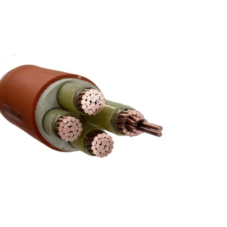
Specifying the wrong cable in an industrial facility rarely announces itself with a single dramatic failure. More often it shows up quietly — a motor circuit running warm, a control signal dropping out during peak production, an armored sheath cracking after six months of flex cycling nobody anticipated. By the time maintenance traces the fault, you’ve lost a shift, scrapped a batch, or triggered an unplanned shutdown that costs ten times what the correct cable would have.
Industrial facilities use several distinct cable categories depending on voltage level, environment, and mechanical duty: power cables (low and medium voltage, typically XLPE or EPR insulated), control and instrumentation cables, flexible trailing cables for moving equipment, data and fieldbus cables, and fire-resistant or explosion-proof rated cables. Selecting the right type means matching conductor size, insulation chemistry, sheath material, and armor configuration to the actual operating conditions of each circuit.
What makes this genuinely complicated — and what procurement managers often underestimate — is that the “correct” cable for a cement plant’s outdoor feeder run shares almost nothing with the right cable for a continuous-flex drag chain in an automotive press line, even if both are rated 600 V. The categories overlap in catalogs but diverge sharply in service life. The rest of this guide works through the major cable types actually used on industrial plant floors, what distinguishes them mechanically and electrically, and how to avoid the specification traps that turn a cost-saving substitution into a reliability problem.
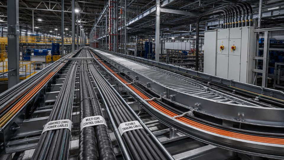
Power Cables for Industrial Plants: Voltage Classes, Insulation Materials, and Armor Options
Every industrial facility runs on a layered power distribution hierarchy, and the cable specification changes at each layer. Getting this wrong — specifying a 1 kV PVC cable on a 6.6 kV motor feeder, for instance — is not a paperwork error. It’s a fire risk and a production shutdown waiting to happen.
Voltage Class Basics and Where Each Tier Lives in the Plant
Low-voltage cables (rated up to 1 kV, per IEC 60502-1) handle the bulk of plant wiring: motor feeders under roughly 200 kW, panel-to-panel runs, lighting circuits, and control power distribution. These are the cables you’ll find in cable trays everywhere from a food processing line to a cement mill.
Medium-voltage cables — 1 kV to 35 kV — step in wherever you’re feeding large drives, ring-main distribution systems, or transformer primaries. A 6.6 kV or 11 kV cable feeding a 1 MW compressor motor is typical in petrochemical and mining plants. The dielectric design becomes critical here: partial discharge performance, conductor screen quality, and insulation uniformity all matter in ways they simply don’t at low voltage.
High-voltage cables above 35 kV are less common on the plant floor itself; they’re usually incoming utility supply or substation interconnects. Still, heavy industrial sites — large smelters, steel mills, LNG terminals — specify 66 kV or 110 kV cables as internal infrastructure.
PVC, XLPE, and EPR: Choosing the Right Insulation
PVC (polyvinyl chloride) is the legacy workhorse. Continuous conductor temperature rating: 70°C. It’s cheap, widely available, and adequate for dry indoor LV applications. The problem shows up in hot environments — a cable tray above a furnace, an enclosed motor control center in a tropical climate — where ambient temperatures push the conductor toward the rating limit faster than most engineers account for. PVC also has poor moisture resistance over long service life and releases toxic HCl gas in a fire, which matters if you’re specifying for tunnels or occupied buildings.
XLPE (cross-linked polyethylene) runs at 90°C continuous, with short-circuit ratings up to 250°C. That higher thermal ceiling translates directly into smaller conductor cross-sections for the same current load — meaning lower copper or aluminum cost per kilometer on long runs. Dielectric strength is superior to PVC, moisture resistance is significantly better, and lifecycle cost per meter tends to favor XLPE on any run longer than a few hundred meters where you’re actually loading the cable to 60–80% of rated capacity. For MV cables, XLPE is essentially the default in modern industrial specifications.
EPR (ethylene propylene rubber) is the specialist choice: flexible even at low temperatures (useful in cold climates or mobile equipment), excellent resistance to ozone and UV, and a 90°C rating matching XLPE. It costs more — typically 15–30% more per meter than XLPE of equivalent rating, depending on conductor size and order volume — but for mining trailing cables or offshore installations it’s often the only sensible answer.
XLPE insulation cables can sustain conductor temperatures up to 90°C continuously and withstand up to 250°C under short-circuit conditions.True
These values are established in IEC 60502 and IEC 60228 standards for XLPE-insulated power cables, verified by routine factory and type testing.
Armor Selection: Environment Drives the Decision
| Armor Type | Best Environment | Typical Crush Load Resistance | Key Trade-off |
|---|---|---|---|
| Steel Wire Armor (SWA) | Direct buried, duct, tray | 450–900 N/cm (gauge-dependent) | Heavy; adds significant weight per km |
| Aluminum Wire Armor (AWA) | Tray, duct, single-core AC runs | Similar range, lighter | Poor in highly acidic soils |
| Steel Tape Armor (STA) | Indoor tray, short duct runs | Moderate — not for direct burial in rocky ground | Less tensile strength than SWA |
SWA is the default for direct-buried runs almost everywhere. The 450–900 N/cm crush resistance range depends on wire diameter and number of armor wires — always check the manufacturer’s test data against your soil conditions and backfill type, not just the catalog spec. On single-core MV or HV cables, SWA creates circulating current problems under AC loads; AWA is specified instead precisely because aluminum’s lower permeability reduces induced losses.
Copper vs. Aluminum: A Bulk Procurement Conversation
Copper’s conductivity is roughly 58 MS/m versus aluminum’s 35 MS/m, meaning an aluminum conductor needs a cross-section about 1.6× larger to carry the same current. Aluminum cable weighs roughly 40–50% less per kilometer than an equivalent copper run, and on bulk orders over a few thousand meters the cost differential can be substantial — aluminum is typically 25–45% cheaper per ampere-meter, though this gap fluctuates with commodity prices. For main distribution runs of 240 mm² and above, aluminum often wins on total cost of ownership. Below 50 mm², termination complexity and minimum bend radius tend to favor copper. Termination quality matters enormously with aluminum; oxidation at joints is the primary failure mechanism, and the plant maintenance culture has to support proper anti-oxidant compound use at every termination.
Standards You Need on the Purchase Order
Specifying “industrial power cable” without citing a standard is an invitation for substitution. IEC 60502 (parts 1 and 2) covers LV and MV cables and is the reference for most international projects. BS 5467 remains common in UK-influenced markets, particularly in the Middle East and South Asia. GB/T 12706 is the Chinese national equivalent and applies to domestically produced cables shipped on projects inside China or by Chinese contractors. UL 1072 governs MV cables sold into North American markets. Before issuing a PO, confirm: which standard governs the project specification, whether third-party type test certificates are required, and whether the factory holds current approval — not just a certificate dated several years ago. Auditing the test report against the actual cable construction offered is worth doing on any order above roughly 20–30 km.
Control Cables: Connecting Switchgear, PLCs, and Motor Control Centers Reliably
Power cables get most of the attention in plant electrical design, but control cables are where reliability actually lives or dies on a daily basis. A tripped relay that fails to signal, a PLC input that reads noise instead of a real sensor state, a motor control center that can’t confirm feedback — these failures rarely make the incident report as “cable problem,” but in practice that’s often exactly what they are.
What Control Cables Actually Do
Control cables carry the nervous system traffic of a facility: switching signals, relay logic, 4–20 mA analog loops, 24 V DC command circuits, and interlock chains between panels, PLCs, field instruments, and actuators. Typical voltage ratings are 300/500 V or 450/750 V — nowhere near the 6.6 kV or 11 kV of your main feeders, but that low signal level is precisely why the cable’s electrical behavior matters more, not less. A stray 5 V of induced noise on a 24 V DC line is a much bigger percentage problem than the same noise on a 400 V power circuit.
Core Count and Cross-Section: Build in Spare Capacity Now
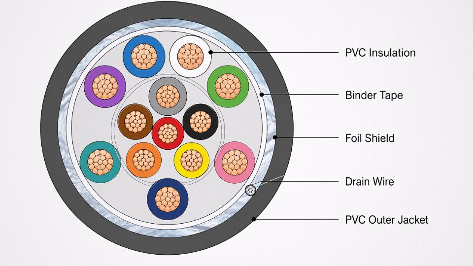
Standard control cables run from 2 cores up to 61 cores, with conductor cross-sections typically between 0.5 mm² and 4 mm², though 6 mm² cores show up in motor feedback or heavier interlock circuits. For most PLC I/O wiring, 0.75 mm² or 1.0 mm² is adequate from a current-carrying standpoint — the limiting factor is usually voltage drop over long cable runs, not thermal load.
The core count decision is where procurement managers and plant engineers often make a costly compromise. Ordering a 12-core cable when you need 10 cores today might save a few dollars per meter at the time of purchase. Two years later, when the plant adds an extra feedback loop or a new interlock requirement, you’re either pulling a whole new cable run or — and this happens constantly — tapping a spare core that was never meant for that signal type. Specifying one cable size up, say 16 or 19 cores on a run where you currently need 12, costs relatively little per meter and eliminates a future re-cabling job that will easily run into thousands in labor alone, depending on conduit routing and accessibility.
Shielded vs. Unshielded: Don’t Guess, Assess the Electromagnetic Environment
Unshielded control cable is fine in clean electrical environments — think a small pump room with no variable-frequency drives nearby, or a simple MCC with direct-on-line starters. The moment you introduce VFDs, large induction motors switching frequently, resistance welding equipment, or long parallel runs alongside 415 V or higher power cables, you need shielding.
An overall copper braid shield (typically 85–95% coverage) handles broadband EMI reasonably well. Foil shields with a drain wire are more common in cost-sensitive multi-core cables and provide good high-frequency attenuation, though the drain wire termination is where installers cut corners and create problems. The shield drain wire must be terminated at one end only — usually the control panel end — and connected to a clean instrument earth, not the general power earth. Grounding both ends creates a ground loop, and you end up injecting exactly the kind of low-frequency interference you were trying to prevent.
Grounding a control cable shield at both ends eliminates interference better than single-end grounding.False
Double-ended shield grounding creates a ground loop that can actively couple low-frequency noise into the signal conductors. Standard practice per IEC and most plant engineering guidelines is single-point grounding, typically at the panel end, connected to a dedicated instrument earth.
Jacket and Insulation Choices by Environment
PVC is the default — cheap, adequate for most indoor industrial use, and widely available in any core count you need. But PVC-C (chlorinated PVC) is worth specifying in petrochemical environments or anywhere the cable might see oil mist, since standard PVC jacket can swell and crack after prolonged hydrocarbon exposure. For food processing lines and areas with regular washdown, LSZH (low-smoke zero-halogen) jackets are increasingly standard not just for fire safety reasons but because the halogens in burning PVC contaminate food-contact environments badly.
Outdoor substation cable runs and anything exposed to direct sun need UV-stabilized outer jackets — a detail that gets missed in procurement when the purchase order just says “PVC control cable” without specifying UV grade. Rubber-jacketed control cables handle vibration and flexing better than PVC in applications like cable tracks on automated equipment, though rubber costs noticeably more and usually needs to be specified as a non-standard item.
Installation Practices That Actually Matter
Segregation from power cables isn’t just a code requirement under IEC 60227 or NEC Article 725 — it’s one of the highest-return practices in plant electrical work. Running control cables in their own dedicated cable tray, separated from power cables by at least 200 mm (more in high-noise environments), reduces interference problems dramatically. Where crossings are unavoidable, cross at 90 degrees. Parallel runs alongside power cables are where most EMI problems originate, and no amount of shielding fully compensates for a 20-meter parallel run at close spacing.
Minimum bend radius for multi-core control cables is typically 8–12 times the overall cable diameter during installation, depending on whether the cable has an armor layer. Violating this — common when cables are pulled around tight conduit bends — can damage insulation on individual cores in ways that don’t show up immediately but cause intermittent faults under thermal cycling. Labeling both ends consistently at installation, using the cable tag number from the electrical drawings rather than a simplified description, sounds obvious but is skipped often enough that it costs real diagnostic hours later.
Instrumentation and Signal Cables: Preserving Measurement Accuracy Across Noisy Plant Environments
Most engineers spend their specification energy on power and control cables, then treat instrumentation wiring as an afterthought. That’s where measurement errors, ghost alarms, and slow process upsets come from.
The fundamental difference from control cable is signal level. A typical 4–20 mA loop runs at milliwatt power levels; a thermocouple output from a Type K pair might produce anywhere from −6 mV to +54 mV depending on temperature range. Compare that to the 24 V or 110 V signals common on control cables. At these levels, a few millivolts of induced noise isn’t an annoyance — it’s a meaningful fraction of your full measurement span. Capacitance between pairs (typically specified as less than 100–130 pF/m for quality instrumentation cable, though this depends on conductor spacing and insulation material) directly limits how fast a 4–20 mA signal can respond over long cable runs. Inductance affects high-frequency interference rejection. Crosstalk between adjacent pairs in a multicore run can corrupt readings on one loop from switching transients on another. These are the specifications that instrumentation cable datasheets exist to address, and they’re the ones procurement teams most often ignore when substituting a cheaper control cable to “save a bit.”
Twisted Pair Construction and Why It Actually Matters
Twisting is not a cosmetic detail. A conductor pair twisted at roughly 12–25 turns per meter picks up electromagnetic interference in equal magnitude on both conductors simultaneously — that’s common-mode noise — and a differential receiver at the instrument input rejects it. An untwisted pair in the same conduit, routed 30–50 meters to a remote flow transmitter near a variable frequency drive, can see induced voltages that push a 4–20 mA reading off by 0.5–2 mA. On a flow loop controlling a batch reactor, that’s real process error, not just noise on a trend historian.
Twist pitch matters too. Tighter twist suppresses higher-frequency interference better. In practice, if you’re routing signal cables near 400 Hz inverter outputs or in areas with dense motor cabling, specify tighter pitch explicitly rather than accepting whatever the manufacturer defaults to.
Individual Pair Shielding Versus Overall Shielding
Here’s where most multicore instrumentation cable specifications go wrong. An overall shield (OS) wraps the entire cable bundle and protects against external electrostatic fields — good for cables routed through general electrical rooms or near lighting. Individual pair shields (IS) isolate each measurement loop from the others inside the same cable. When you’re carrying six or eight separate 4–20 mA loops in one multicore cable, an OS-only design does nothing to prevent crosstalk between loop 3 and loop 7. IS+OS construction costs roughly 15–35% more depending on conductor count and shield material, but for multi-loop instrumentation cables in process plants — especially near motor drives, heat tracing circuits, or welding areas — it’s the only configuration that actually works.
Rule of thumb: single-loop signal runs in dedicated conduit, OS is usually adequate. Multiple independent measurement loops sharing one cable, always specify IS+OS. Mixed-signal cables carrying both thermocouple and 4–20 mA circuits in the same sheath should be avoided if at all possible, though in retrofit situations you often don’t have that luxury.
Thermocouple Extension and Compensating Cables
This segment causes more calibration headaches than almost anything else in instrumentation wiring, usually because someone substituted copper cable at the last meter between the extension wire and the transmitter head.
Thermocouple extension cables must use the same alloy pair as the thermocouple junction — Type K uses nickel-chromium/nickel-aluminum conductors, Type J uses iron/copper-nickel, Type T uses copper/copper-nickel, and so on through the IEC 60584-3 series. IEC 60584-3 also defines color codes: Type K overall sheath is green (with a yellow positive and green negative conductor in most IEC-compliant cable), though older installations using ANSI color coding will have yellow overall with yellow positive and red negative — a genuinely dangerous inconsistency if you’re extending a legacy installation. Always verify the color standard in use before connecting.
Compensating cables use different alloys that approximate the thermoelectric properties of the original thermocouple pair over a narrower temperature range, typically ambient conditions in the cable run rather than the measurement point. They’re cheaper but introduce a small calibration offset if the cable itself sees elevated temperatures above roughly 60–80°C. In hot utility tunnels or near furnaces, use matched extension cable, not compensating cable.
Loop resistance budget matters more than engineers typically account for. A Type K run of 80–100 meters using 1.5 mm² extension cable might add 10–15 Ω to the loop. Some older transmitter inputs have input impedance specifications sensitive to source resistance — check the transmitter datasheet, not just the cable spec.
Substituting copper instrument cable for thermocouple extension wire introduces a parasitic thermoelectric junction at the substitution point, creating a systematic measurement error.True
Copper conductors have a different Seebeck coefficient than thermocouple alloy conductors. Any junction between dissimilar metals at a point of unknown temperature generates its own thermoelectric EMF, which the transmitter cannot distinguish from the measurement signal.
Hazardous Area Instrumentation Cables
Intrinsically safe (IS) circuit cables in ATEX/IECEx Zone 1 and Zone 2 areas carry specific requirements that go beyond basic instrumentation cable specifications. Blue sheathing is the standard identifier for IS circuits under IEC 60079-14, and it’s not decorative — it tells maintenance technicians that this cable is part of a certified IS loop and must not be connected to non-IS equipment without breaking the certification.
The certification requirement covers the cable itself, not just the barrier. Cable capacitance and inductance per unit length must fall within the certified entity parameters of the IS barrier or isolator. Exceeding the certified cable length or using a cable with higher capacitance than the barrier’s Ci/Li rating can, in theory, allow sufficient stored energy to cause ignition in a gas atmosphere.
Substituting uncertified cable in Zone 1 is not a minor paperwork violation. It voids the IS circuit certification, which means your explosion protection depends entirely on the cable not being damaged — no certified margin, no regulatory defense, and significant liability exposure if an incident occurs. In practice, plant auditors find IS circuit violations more often than almost any other instrumentation wiring issue, usually introduced during maintenance or expansion work when the original IS cable wasn’t in stock.
Industrial Data, Fieldbus, and Ethernet Cables: Supporting Industry 4.0 Communication Networks
The wiring conversation in most plants starts with power and control, then somebody mentions the PROFIBUS trunk is running next to a 690 V VFD feed and the whole automation team gets nervous. Rightfully so. Data cables in a factory environment face a completely different set of stresses than the same cables would face in an office building, and the physical layer is where most fieldbus reliability problems actually originate — not in the PLC logic, not in the configuration.
Matching Cable to Protocol: It’s Not Interchangeable
PROFIBUS DP uses a specific bus cable — violet sheath, twisted pair, nominally 150 Ω characteristic impedance, with a braid-plus-foil shield tied to ground at one end only. Deviate from that impedance and you get reflections; at baud rates above 1.5 Mbit/s the segment starts dropping nodes, usually intermittently, which makes it genuinely difficult to diagnose. The standard cable, sometimes called “PROFIBUS Type A,” has a capacitance well under 30 pF/m — commercial telephone cable won’t cut it.
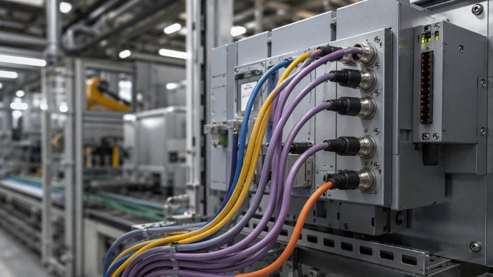
PROFINET runs on industrial Cat 5e or Cat 6, but “industrial” means something specific here. The jacket needs to be UV-stabilized PUR or at minimum a rated polyurethane compound, the connectors need to achieve IP67 or IP69K sealing (M12 D-coded being the dominant form factor in European plant installations), and the pairs need to pass TIA-568-C.2 and IEC 61156-6 for 100 MHz transmission. Ordinary commercial patch cable pulled through a cable tray near a conveyor drive will last a season, maybe less.
DeviceNet — still common in older automotive and food-processing lines — uses a round thick or thin cable with a very specific color-coded construction: two signal conductors (white CAN_H, blue CAN_L), two power conductors (red 24 VDC, black 0 V), and a drain wire inside an aluminum foil shield. The thick cable runs trunk lines up to roughly 500 m at 125 kbit/s; thin cable serves drops. Mixing thick and thin incorrectly on the same segment is a classic commissioning mistake.
Modbus RTU over RS-485 needs 120 Ω impedance cable — unterminated stubs or wrong-impedance cable causes waveform distortion that manifests as CRC errors, usually worse in the afternoon when ambient temperature rises and the bus loading shifts slightly. EtherNet/IP, being Ethernet underneath, uses the same industrial Cat 5e/6 construction as PROFINET.
Industrial Ethernet Versus What You’d Pull From the IT Closet
The conductor is only part of the story. Commercial Cat 6 is tested in conditioned lab environments with controlled bend radius and no mechanical cycling. On a factory floor near a stamping press, the cable flexes, vibrates, and occasionally gets hit. Industrial Ethernet cable uses stranded conductors rather than solid, a mechanically robust PUR outer jacket with a wall thickness typically in the 0.8–1.2 mm range, and the pairs are individually foil-shielded plus an overall braid — that combination matters when the cable is within a few meters of a variable speed drive or an induction furnace bus bar.
Commercial Cat 6 patch cables are electrically equivalent to industrial Ethernet cables for factory automation useFalse
Commercial Cat 6 uses solid conductors and unshielded PVC jackets tested only to office environment standards. Industrial Ethernet cables use stranded conductors, PUR jackets rated for mechanical abuse and UV exposure, and foil-plus-braid shields — all required for reliable operation near VFDs, high-current bus bars, and areas with washdown cycles.
Fiber Optic Cable: When Copper Runs Out of Options
Near high-power induction furnaces or in plants with unavoidable ground loop issues, copper data cable simply cannot guarantee signal integrity regardless of how well it’s shielded. That’s where fiber becomes the rational choice rather than a premium one.
For in-plant runs under 300 m — machine-to-machine, PLC-to-HMI, local Ethernet ring segments — multimode OM3 or OM4 fiber is the standard workhouse. OM4 supports 10 GbE at distances up to roughly 400 m and handles most in-building industrial scenarios comfortably. Single-mode OS2 comes into play for inter-building connections, long-distance SCADA uplinks, or any run above 500 m where you need bandwidth headroom for future growth.
The jacket construction matters too. Tight-buffer fiber handles short, terminated indoor runs well; loose-tube construction is preferable outdoors or in environments with thermal cycling, because the buffer gel or dry fill accommodates the differential expansion that would otherwise stress the glass. In food and pharmaceutical plants with aggressive washdown, armored tight-buffered designs with IP67-rated push-pull connectors (LC or SC) are fairly standard.
EMI Hardening Near Drives and Furnaces
Variable speed drives — especially older IGBT types switching at 4–16 kHz — generate common-mode noise that couples into adjacent data cables over surprisingly short distances, sometimes 30–40 cm of parallel routing in a shared tray. Foil-plus-braid combination shields on quality industrial data cable typically achieve shielding effectiveness in the 85–95 dB range across the 10–100 MHz band, which handles most VFD harmonic frequencies. That said, physical separation and segregated trays are still the first line of defense; shielding covers what separation can’t.
Hybrid Cable: Elegant on Paper, Complicated in Practice
Hybrid cables bundling power conductors and data pairs under a single jacket are becoming genuinely common in robotic arm installations and AGV charging lanes, where running separate conduits through a moving cable carrier is mechanically awkward. In principle it simplifies the drag chain and reduces the overall diameter. In practice, there are real trade-offs. Power conductors generate heat inside the bundle, which elevates the temperature seen by the data pairs — this can shift impedance slightly and, in a worst case, accelerates jacket degradation. Troubleshooting is also less straightforward; when a fault develops, isolating whether it’s in the power conductors or the data pairs without cutting into the jacket requires proper test equipment and patience. For a purpose-built robotic cell with controlled bending radius and documented flex cycle life, hybrid cable makes sense. For a general power-plus-comms run through a cable tray, separate cables remain the more maintainable approach.
Fire-Resistant and Low-Smoke Zero-Halogen (LSZH) Cables: Meeting Life-Safety and Evacuation Standards
Most procurement teams encounter fire-performance cable specs late in a project — usually when the fire engineer or authority having jurisdiction stamps a comment on the cable schedule. By that point, substituting cable types gets expensive fast. Understanding what each classification actually requires, and why, saves that scramble.
Three Distinct Performance Tiers — Not Interchangeable
Flame-retardant (FR) cables are the baseline. They resist ignition and limit flame spread along the cable route, but once a fire is burning hot enough, circuit continuity fails. That’s acceptable for general wiring where the circuit doesn’t need to survive the fire itself.
Fire-resistant cables — sometimes marked FR-R or simply “circuit integrity” cables — are a different animal. The insulation system is designed to maintain electrical function during a fire of specified severity and duration. IEC 60331-1/2 defines the test: 750°C for a minimum period, with the cable energized and monitored for continuity. These are the cables powering fire pumps, alarm panels, and emergency lighting.
The enhanced tier, E90, extends that circuit integrity to 90 minutes of maintained operation under IEC 60331-21/25 conditions — 930°C flame temperature with mechanical shock applied simultaneously. If your building’s fire strategy says “90-minute maintained supply,” an E30-rated cable won’t satisfy the certifier regardless of what the datasheet says elsewhere. I’ve seen this mismatch on more than one project submittal.
What LSZH Actually Means at the Chemistry Level
LSZH (low-smoke zero-halogen) is a sheath and insulation compound specification, not a fire-resistance rating. Cross-linked polyolefin or EVA-based compounds replace PVC, keeping HCl emission below 0.5% by mass per IEC 60754-1 and limiting smoke density so that light transmittance stays above 60% in the IEC 61034-2 chamber test.
Why does that matter operationally? In a tunnel, offshore module, or an atrium connecting an industrial facility to a public terminal, combustion gases from a standard PVC cable can incapacitate occupants before the fire itself becomes life-threatening. Dense black smoke also defeats emergency lighting faster than people expect — tested visibility at floor level collapses within minutes. LSZH compounds cut both problems simultaneously.
The critical point procurement managers must internalize: LSZH and fire-resistant are independent properties. A cable can be LSZH without maintaining circuit integrity (common in general building wiring), fire-resistant without being LSZH (older mineral-insulated cables have no organic sheath at all), or both — which is what offshore platform topsides and metro stations typically specify.
Mineral-Insulated Cables: The High-Temperature Extreme
MI cables — magnesium oxide packed between a copper conductor and a copper or stainless-steel outer sheath — sit at the top of the thermal performance ladder. Continuous operation at 250°C, survival through a 950°C furnace test, and physical robustness that LSZH compounds simply can’t match. Emergency fire pump feeders, smoke-control fan circuits, and reactor safety system supplies in nuclear facilities are the typical applications. The trade-off is cost (roughly 3–6× a comparable XLPE armored cable, depending on conductor size and sheath material) and inflexible installation — MI cable doesn’t bend repeatedly without termination damage, so routing has to be planned carefully up front.
Regulatory Triggers by Sector
The standards landscape is genuinely fragmented, which causes real procurement errors.
| Sector / Region | Governing Standard | Key Requirement |
|---|---|---|
| EU construction projects | EN 50575 / CPR (EU 305/2011) | Euroclass performance declaration (Eca through Aca) |
| UK buildings | BS 7846 | Circuit integrity categories, LSZH options |
| Global industrial / IEC-basis projects | IEC 60331 series | Circuit integrity under flame test |
| Transit / rail facilities | NFPA 130 (US), EN 45545-2 (EU rail) | Flame spread, smoke, toxicity combined |
| Offshore / marine | IEC 60092-359, NEK 606 | Mud-resistant, fire-resistant, LSZH |
EN 50575 catches engineers off guard because it applies by default to any cable permanently installed in a construction work within the EU — including industrial plants. The CPR Euroclass is a declaration requirement tied to CE marking; omitting it from a cable procurement spec for an EU project creates a compliance gap that customs or the building authority may flag.
LSZH cables emit less than 0.5% HCl gas under IEC 60754-1 test conditions, compared to PVC cables which can emit 20–28% HCl by mass during combustionTrue
IEC 60754-1 sets the halogen acid gas emission test; LSZH compounds are formulated to pass the 0.5% threshold, while PVC contains 30–57% chlorine by weight, yielding significant HCl during combustion — a well-established electrochemical fact.
The Specification Mistake That Keeps Recurring
Ordering flame-retardant cable when the fire strategy document specifies fire-resistant circuit integrity is the single most common error I’ve seen on industrial construction projects. The two look similar in a cable datasheet summary, the price difference encourages the wrong substitution under procurement pressure, and the problem only surfaces during commissioning sign-off or — worst case — a real fire.
The fix is straightforward: pull the fire strategy report before writing the cable schedule. Every circuit that must operate during or after ignition needs FR-R or E90 classification documented on the single-line drawing, not just a general note on the spec cover sheet.
Mining, Oil and Gas, and Heavy-Industry Specialty Cables: Engineered for Extreme Conditions
Standard armored power cable that performs flawlessly in a substation or a manufacturing hall will fail — sometimes catastrophically — once it moves into a longwall mining face, a subsea umbilical bundle, or the hot zone of an aluminum smelter. The failure modes are different from anything an office-spec’d cable encounters: continuous mechanical flexing, hydrocarbon immersion, hydrogen sulfide attack, or sustained radiant heat that simply exceeds what XLPE or PVC can tolerate. Getting the specification right here isn’t about premium product selection for its own sake — it’s about avoiding unplanned shutdowns in places where a shutdown costs five or six figures per hour.
Mining Trailing and Reeling Cables
A trailing cable on a continuous miner or a shuttle car is in motion for most of its service life. It flexes through tight radii, gets driven over, dragged across wet rock, and sometimes partially buried under spoil. PVC and XLPE constructions crack. The correct construction uses stranded copper with fine-wire bundles (often Class 5 or 6 stranding), insulated in ethylene propylene rubber (EPR), and sheathed in CPE (chlorinated polyethylene) or polychloroprene — both of which resist oil, ozone, and mechanical abuse simultaneously.
Voltage ratings run 1.1 kV for face equipment up to 3.3 kV and 6.6 kV for longwall drives and underground main cables. Every design includes a dedicated ground continuity conductor, typically monitored by a pilot circuit so a broken earth trips the circuit before anyone touches the machine. Compliance benchmarks are IEC 60502-1 for general construction and AS/NZS 2802 for Australian and South African underground mining environments specifically.
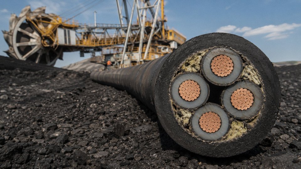
Mining trailing cables must include a monitored ground continuity conductor under IEC 60502-1 and AS/NZS 2802 to provide a detectable earth-fault path before energized equipment becomes a contact hazard.True
Both standards mandate ground continuity conductors in flexible mining cables; the pilot-monitoring requirement exists specifically to protect personnel in wet underground environments where standard earth-fault protection may respond too slowly.
Offshore and Subsea Cables
Shallow-water platform cables face salt spray, UV, vibration from deck machinery, and the occasional impact from lifting gear. Deepwater umbilicals add hydrostatic pressure — at 1,000 m depth you’re looking at roughly 100 bar — and permanent immersion in cold, biologically active seawater.
Double steel wire armor (DSWA) is the baseline for mechanical protection, with the interlayer filling typically bitumen-impregnated polypropylene yarn to resist water migration along the cable core. Aluminum sheathing is avoided in permanently submerged designs because of galvanic corrosion risk; stainless steel or lead alloy is used instead. Hydrostatic pressure testing for deepwater umbilicals is conducted at 1.5× design depth pressure, held for a minimum duration specified in the project engineering standard — usually DEF STAN or a project-specific STS derived from it.
Oil and Gas Plant and FPSO Module Cables
On an FPSO or in an onshore gas processing module, you’re dealing with three simultaneous problems: potential hydrocarbon exposure, classified hazardous areas (Zone 1 and Zone 2 under IECEx), and the need to limit flame spread in enclosed spaces where evacuation is slow. Outer jacket compounds must resist H₂S — even low concentrations attack PVC over time, causing surface cracking that undermines the jacket’s mechanical protection. Mud-resistant jackets are specified for any run that passes through drilling areas or pipe decks.
API RP 14F governs electrical system design on floating production facilities and drives cable selection criteria. IEC 60079-14 handles installation in hazardous areas. These are not interchangeable — a cable that satisfies one may still fall short of the other, and procurement teams that source against only one standard sometimes discover the gap during third-party verification audits.
High-Temperature Cables for Steel Mills, Glass Furnaces, and Smelters
Silicon rubber insulation, rated 180°C continuous (some grades push to 200°C), handles most hot-zone sensor and control wiring in steel and aluminum facilities. For runs inside or immediately adjacent to furnace openings — glass tank crowns, aluminum reduction cell hoods — silicone alone isn’t enough. Ceramic-wrapped cables with fibreglass braid overcoverings extend service temperature toward 600–900°C for short runs, though they’re brittle and can’t flex once installed. In practice, the solution is usually a combination: silicone-insulated cable routed to within a meter or so of the heat source, then transitioned to ceramic-wrapped conductors for the last section. Running silicone cable directly past an open furnace door is a maintenance habit that shortens cable life dramatically, regardless of the datasheet rating.
Chemical Plant and Wastewater Applications
Immersion and splash of acids, caustics, and industrial solvents drive jacket selection here more than voltage or temperature. Testing is done per IEC 60811 series — mass loss, elongation retention, and hardness change after immersion in specified media. PVDF (polyvinylidene fluoride) jackets offer outstanding resistance to concentrated acids and chlorinated solvents. TPU (thermoplastic polyurethane) handles abrasion and moderate chemical exposure well and is often the right balance of flexibility and resistance in wastewater and fertilizer plant environments where the chemical mix is variable rather than concentrated. Neither is cheap, and specifying PVDF across an entire project when TPU would suffice in most areas is a procurement cost that adds up — but specifying TPU in a chlor-alkali splash zone is a failure waiting to happen.
Industrial Cable Selection Matrix: Matching Application, Environment, and Standard in One Decision Framework
The sections above cover a lot of ground. What follows is the synthesis — a working reference you can hand to a junior engineer or drop into a procurement package without re-reading everything from the top.
The Matrix
| Industry Sector | Cable Family | Conductor Size Range | Insulation / Jacket | Armor Requirement | Key Standard |
|---|---|---|---|---|---|
| General manufacturing — LV power | Power cable | 2.5–240 mm² | XLPE / PVC | SWA where mechanically exposed | IEC 60502-1 |
| Petrochemical — MV motor feeder | Power cable | 35–185 mm² | XLPE / LSZH | SWA or AWA (Zone 1/2) | IEC 60502-2, IEC 60079 |
| Food & beverage — motor control | Control cable | 1.0–2.5 mm², 4–24 cores | PVC or LSZH / PVC | Unarmored or braided | IEC 60227, MESC / customer spec |
| Water treatment — SCADA instrument loop | Instrumentation cable | 0.5–1.5 mm², paired | PE / LSZH, overall + individual screen | Unarmored, or SWA for buried runs | IEC 60544, ISA-5 |
| Automotive plant — DeviceNet fieldbus | Data / fieldbus cable | Per DeviceNet spec (18 AWG signal) | PE / PVC | Unarmored, flex-rated | ODVA DeviceNet specification |
| Steel / metals — crane trailing | Flexible power + control | 1.5–50 mm² | EPR or PCP jacket | Chain-guided, no rigid armor | IEC 60245, VDE 0250 |
| Mining — in-pit trailing | Mining flexible | 25–300 mm² | EPR / CPE | None (flexible design), earthing cores | AS/NZS 1802, IEC 60502 |
| Offshore / marine platform | Marine power | 2.5–120 mm² | EPR / LSZH | SWA or braid-over-braid | IEC 60092-350/-353 |
| Tunnel / metro — traction feeder | Fire-resistant power | 16–240 mm² | Mica-glass / LSZH | SWA | IEC 60331, EN 50200 |
| Building services in industrial complex | LSZH control | 1.0–1.5 mm², 2–12 cores | LSZH throughout | Unarmored (in conduit) | IEC 60332-3, EN 50575 |
Conductor sizes assume copper unless the project spec explicitly permits aluminum. Armor type depends on soil chemistry for buried runs — chloride-rich ground attacks steel wire armor faster than most engineers expect, and AWA is the right call there.
Worked Example 1 — 400 V Motor Feeder, Petrochemical Zone 2
A pump motor rated 75 kW sits roughly 120 m from the MCC in a Zone 2 classified area. Voltage class: 0.6/1 kV minimum, so IEC 60502-1 LV cable applies. Full-load current runs somewhere around 140–150 A depending on power factor; with a 120 m run and the derating for ambient 40 °C plus possible grouping, you’ll likely land on 95 mm² copper XLPE. Jacket must be LSZH because the area has limited natural ventilation. Armor: SWA, because the cable runs partly in open cable tray and partly in a congested pipe rack where mechanical damage is realistic. The IEC 60079 Zone 2 classification doesn’t change the cable construction per se, but it does mandate that any gland into the junction box is certified EEx-e or EEx-d — a detail that gets missed until the site inspection.
Specify the wrong insulation material (PVC instead of LSZH) here, and you’ll likely fail the project’s area classification review. Specify unarmored, and the first time a rigger drops a scaffold board across that tray, you have an unplanned outage.
Worked Example 2 — Multicore Instrumentation Cable, Water Treatment SCADA, 800 m Run
An 800 m run to a remote I/O panel serving flow, pressure, and pH transmitters. Signal levels are 4–20 mA. At that distance, individual pair screening plus a collective overall screen is non-negotiable — without it, a variable-speed drive somewhere along the route will inject enough noise to drift your pH reading by half a unit. Conductor: 0.75–1.0 mm² twisted pairs, PE insulated. Jacket: LSZH if the cable enters the control building (which it will). If the route is partly direct-buried, add SWA and specify a sacrificial corrosion jacket over the armor. Overall, this lands on something like a 12-pair, 1.0 mm² individually screened, overall screened, SWA, LSZH cable to IEC 60544.
One thing worth checking: the trench likely passes within meters of medium-voltage transformer earth electrodes. Induced voltages can be significant. That’s an argument for drain wire continuity at one end only, grounded at the control room — a classic mistake when site electricians “helpfully” terminate both ends.
Five Specification Errors That Show Up Constantly in Tender Documents
Wrong voltage class. A 0.6/1 kV cable on a 3.3 kV system. It happens, usually because someone copied a previous project spec without checking the distribution voltage. The fix is five seconds of attention during cable schedule review.
Omitting armor on mechanically exposed routes. “It’ll be in conduit” is not always true by the time construction finishes. Specify SWA by default for any outdoor or plant-floor run and let the contractor justify an exception.
PVC jacket in an LSZH-required zone. Some older standard specs still default to PVC. If the area classification document or the building regulation requires LSZH (common in enclosed substations, tunnels, and any occupied building), PVC fails compliance regardless of how many other specs it meets.
Under-counting control cable cores. Projects routinely specify 12-core control cables and then add signals during detailed engineering until the cable is full, then run a second cable for the overflow — costing double the termination labor. Add 20–25% spare cores at the scheduling stage. It costs almost nothing in cable price and saves real money on installation.
FR versus FIR confusion. Fire-resistant (FR) cables maintain circuit integrity during fire. Flame-retardant cables resist ignition and limit flame propagation but do not guarantee continued operation. These are not interchangeable. Emergency lighting, fire pump feeders, and safety system cables need FIR (or the IEC 60331 equivalent). Using a flame-retardant cable where fire-resistant is required is a life-safety failure, not just a spec error.
IEC 60331 fire-resistant cables maintain circuit integrity for a defined period under fire exposure, which is fundamentally different from IEC 60332 flame-retardant cables that only limit flame spread.True
IEC 60331 specifies a circuit integrity test where the cable must continue to function electrically while exposed to flame at 750–950°C for a defined duration. IEC 60332 tests only whether the cable self-extinguishes and limits flame propagation — it does not test continued electrical operation under fire conditions. Confusing the two standards in safety-critical applications is a known compliance failure mode.
How Jinda’s Application Engineering Team Works Through This
Cable schedules for large projects can run to hundreds of lines, and the errors above tend to cluster in the first draft — usually because the schedule was built from a generic template rather than a site-specific review. Jinda’s application engineers review cable schedules at the pre-order stage, cross-checking voltage class, core count, armor type, and fire performance designation against the area classification drawings and applicable standards. That review is backed by an in-house laboratory across five production facilities covering everything from conductor resistance checks to full IEC 60331 fire-integrity testing. Factory acceptance testing can include third-party witness if your project QA plan requires it. For procurement managers dealing with multi-country supply chains, Jinda also provides full traceability documentation — mill certificates, drum records, and test reports — formatted to the major international project documentation standards.
It’s not a complicated service. It’s just the kind of upfront technical alignment that stops specification errors from becoming site problems.
Industrial Cable Standards, Testing, and Third-Party Certification: What to Demand from Your Supplier
Every specification sheet looks acceptable on paper. The real question is whether the cable on the reel matches what the document claims — and that gap is where projects get into trouble.
How the Major Standards Families Relate (and Where They Diverge)
IEC standards form the global technical baseline. IEC 60228 governs conductor classes and resistance limits; IEC 60502 covers extruded insulation for voltages from 1 kV to 30 kV; IEC 60332 addresses flame propagation. Most national standards either adopt IEC directly or derive from it with local amendments.
BS/EN standards used across Europe and the UK are largely harmonized with IEC, but there are persistent divergences worth knowing. BS 5467 and BS 6724, for instance, specify SWA and AWA armored cables with conductor resistance limits and insulation thickness tolerances that are subtly different from the equivalent IEC 60502 values — enough to matter on a large motor feeder calculation. The CE marking requirement for cables entering the EU market is tied to the Construction Products Regulation (CPR), which mandates declared fire performance (Euroclass ratings Aca through Fca). That’s a legal obligation, not just a quality preference.
UL and CSA standards diverge more sharply. UL 44 (thermoset-insulated wire), UL 83, CSA C22.2 — these use conductor resistance tables and voltage withstand test levels built around North American installation practices, 60 Hz systems, and different conductor stranding conventions. A cable certified to IEC 60502 is not automatically compliant for installation in a facility governed by the NEC or CEC. This trips up procurement teams sourcing from Asian manufacturers for North American greenfield projects more often than it should.
GB/T standards from China largely mirror IEC in structure, though the permissible tolerances in older GB standards sometimes allowed slightly thinner insulation walls than IEC equivalents. More recent GB/T revisions have tightened this considerably. AS/NZS standards (notably AS/NZS 5000 series) also track IEC but include specific requirements for Australian environmental conditions — UV resistance, termite resistance in some segments — that you won’t find called out explicitly in IEC.
Routine Tests Versus Type Tests: A Distinction That Gets Exploited
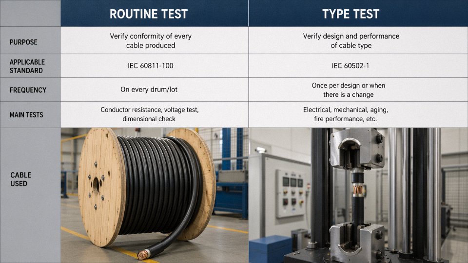
Every production reel must pass routine tests: conductor resistance measurement, spark test on the insulation line, and a completed-cable voltage withstand. These are not optional quality checks — they’re mandatory per IEC 60502-1 and equivalent standards. If a supplier cannot provide individual reel test records with reel serial numbers, that’s a non-starter.
Type tests — fire performance per IEC 60332-3, mechanical impact on armor, long-term aging — are conducted once on a representative design sample, sometimes years before your order ships. A certificate for a type test does not guarantee every production reel was made identically. Suppliers occasionally present a type test certificate for a premium design to support sales of a lower-spec variant. Always check that the cable designation on the certificate exactly matches the cable designation on your purchase order and the drum marking.
Third-Party Certification Bodies: What the Certificate Actually Covers
KEMA, SGS, Bureau Veritas, TÜV, and Intertek all issue cable test certificates. What differs is the scope. A one-time witnessed test (common with SGS or BV) confirms only the sample submitted. Ongoing factory surveillance schemes — where the certifying body conducts periodic unannounced production audits and re-tests production samples — provide meaningfully stronger assurance. When you’re sourcing 50,000 meters for a critical installation, ask specifically which scheme applies.
Request test reports that include the test date, the cable sample reference, and if possible the production batch. For major project orders, it’s entirely reasonable — standard practice in the power and petrochemical sector — to require that your nominated third-party body witnesses factory acceptance testing before shipment. Reputable manufacturers will accommodate this. Reluctance to allow witness testing is itself a signal.
A cable type test certificate issued years ago guarantees the currently shipped cable meets the same specification.False
Type test certificates validate a cable design at the time of testing on a specific sample. They do not automatically cover production changes in materials, dimensions, or processes made after the original test. Procurement teams should verify the current production cable designation matches the certificate exactly and check the certificate date relative to any known product revisions.
Red Flags Worth Taking Seriously
Cable weight per kilometer is one of the most reliable independent checks available without a laboratory. Theoretical weight is calculable from the specified conductor cross-section, insulation thickness, and armor wire diameter. If delivered cable weighs noticeably less — say, 8–15% under theoretical — that almost always means under-sized conductors, thinner insulation, or lighter armor than specified. In practice, a quick drum weigh on arrival, compared against the data sheet figure, catches a significant proportion of under-specification issues before installation.
Other consistent warning signs: no reel-level test records, missing or vague drum markings (conductor size, voltage rating, standard, manufacturer), CE marking absent on EU-bound cable, and pricing sitting more than roughly 20–30% below the credible market range for that specification. That last one deserves a blunt statement — cable is a material-cost-driven product. Copper and aluminum prices are public. There is a floor below which something has to give, and it is never the manufacturer’s margin.
Jinda’s Quality Infrastructure
Shandong Jinda operates under an ISO 9001-certified quality management system across its production bases. The in-house laboratory runs high-voltage withstand testing, conductor resistance verification, mechanical tests including armor crush and impact, and fire performance testing per IEC 60332. For major project orders, Jinda accepts third-party witness testing at the factory — SGS, BV, TÜV, or a customer-nominated body. Test records are issued with reel-level traceability so procurement teams can match documentation to the specific drums in a shipment, not just to the cable type in general.
That level of traceability should be a baseline expectation from any supplier you’re seriously evaluating, not a premium service.
Frequently Asked Questions About Industrial Cables
What is the difference between a power cable and a control cable — and can one substitute for the other?
Power cables carry load current to motors, transformers, and distribution panels. Their conductors are sized for thermal capacity under continuous current — typically 2.5 mm² up to 630 mm² or larger. Control cables run command and feedback signals between PLCs, relay panels, and motor control centers; individual conductors are usually 0.75–2.5 mm², and the electrical stress is milliamps, not amps.
Substitution causes two distinct problems. First, a control cable pressed into service as a power cable will overheat because its insulation system and conductor sizing are not rated for the load current — you’ll get premature insulation breakdown, possibly a fire. Second, using a power cable core for a 4–20 mA signal circuit creates excessive capacitance and resistance on the loop, which distorts the signal, and in a multi-pair run the lack of individual-pair shielding introduces crosstalk. Beyond functional failure, most plant electrical codes (IEC 60364, NEC, etc.) treat these as distinct cable categories with separate installation and marking requirements. An inspector will flag it. Don’t substitute.
When is armored cable required versus unarmored cable in an industrial facility?
The short answer: anywhere the cable faces a credible mechanical threat that conduit or cable tray protection cannot reliably eliminate. Direct burial is the clearest case — unarmored cable underground will eventually be damaged by ground movement, rodent activity, or inadvertent digging. SWA (steel wire armored) or AWA (aluminum wire armored) cables are essentially mandatory here, and their crush resistance — roughly 450–900 N/cm depending on armor gauge — provides the physical protection that soil and frost cycles demand.
Inside a plant, the decision is more contextual. Cable routed in rigid steel conduit through a clean, low-traffic electrical room? Unarmored XLPE is fine and easier to terminate. Cable crossing a machine shop floor, running alongside conveyors, or installed in a tray exposed to forklift traffic? Armor or at minimum heavy-duty mechanical protection is prudent. High-fault-energy environments — furnace areas, large motor feeders, switchgear rooms — often specify armored construction as a containment measure in the event of a cable fault. Check your local wiring regulations and, honestly, ask the maintenance team what they’ve damaged before.
What does LSZH mean, and where is it mandatory versus recommended?
LSZH stands for Low Smoke Zero Halogen. In a fire, standard PVC cables release hydrogen chloride gas, which is both toxic and corrosive to electronics. LSZH compounds — typically based on EVA, XLPO, or similar polymers — suppress smoke density and eliminate halogen acid gases. EN 50575 (the European CPR regulation) classifies cables from Aca down to Fca; confined spaces and public buildings often require Cca or better.
Mandatory applications in most jurisdictions include offshore platforms, underground rail, tunnels, data centers, airports, hospitals, and any space where evacuation is slow or ventilation is limited. Recommended — meaning the project spec usually calls for it even when local code doesn’t — includes control rooms, cable basements in chemical plants, and any installation where toxic smoke could incapacitate personnel before they reach exits. In some Gulf and Southeast Asian projects the local authority having jurisdiction (AHJ) mandates LSZH for all indoor cable regardless of occupancy type. Check the project’s Fire & Life Safety specification before finalizing the cable schedule.
How do I calculate the correct cable cross-section for an industrial motor circuit?
Start with full-load current from the motor nameplate, then work through four checks in sequence:
- Ampacity after derating: Apply IEC 60364-5-52 (or equivalent) derating factors for installation method, ambient temperature (a cable tray in a hot furnace bay might derate 20–30%), and cable grouping. Cables bunched together share heat; six cables touching in a tray can drop the allowable current to 60–70% of the single-cable rating.
- Voltage drop: For motor circuits, most standards allow 3–5% drop from the supply point to the motor terminals at full load. Over a 200 m run, this constraint frequently governs the cross-section rather than ampacity.
- Short-circuit capacity: The conductor and insulation must survive the maximum prospective fault current for the clearance time of the upstream protection. For XLPE insulation, the short-circuit temperature limit is 250 °C — use the adiabatic equation (conductor cross-section ≥ I × √t / k) to verify.
- Motor starting current: High-inertia loads with 600–700% starting current need a voltage drop check at starting conditions too, not just full load.
XLPE insulation cables can operate continuously at conductor temperatures up to 90°C and withstand short-circuit temperatures up to 250°C.True
These values are defined in IEC 60502 and IEC 60364 for XLPE-insulated cables — 90°C continuous operating temperature and 250°C short-circuit limit — and are standard industry reference figures used in cable sizing calculations.
A quick consequence check: undersizing by one cross-section step (say, 16 mm² instead of 25 mm²) in a hot, grouped installation can reduce insulation life from decades to a few years due to continuous thermal stress above rated temperature.
What is the MOQ when sourcing industrial cable from a manufacturer, and how are large international orders handled?
For standard catalog sizes — common power cables, basic control cables — realistic MOQs from a manufacturer like Jinda typically run 500–2,000 m per line item, though this depends on conductor size, insulation system, and how much of the production run setup cost the minimum quantity needs to absorb. Specialty cables (trailing cables, fire-resistant screened multicore, custom voltage ratings) usually require project-specific MOQ discussions; sometimes 500 m is feasible, sometimes the minimum economical run is 2,000–5,000 m.
Lead times realistically range from 4 weeks for stock-sized cable to 10–12 weeks for complex specialty constructions, especially when third-party witness testing or specific certification marks are required. Large international orders are typically packed on wooden drums or steel reels, containerized (20 ft or 40 ft), and shipped with a full documentation package — test certificates, packing lists, material safety data sheets, country-of-origin certificates, and customs HS code documentation. Experienced manufacturers will also coordinate with freight forwarders and provide the necessary LC or documentary credit paperwork. If your project has a phased delivery schedule, discuss staggered releases upfront; holding finished cable in a manufacturer’s warehouse for six months while civil works catch up is a commercial arrangement worth negotiating early, not at the last minute.
How long does industrial cable typically last, and what causes premature failure?
Fixed installations under rated conditions should last 20–40 years. The wide range reflects installation quality, environment, and how consistently the cable operates near its thermal limit. A cable running at 60% of its rated current in a moderate ambient temperature will outlast one running at 90% of rated current in a 45 °C cable basement every time.
The top causes of premature failure, roughly in order of frequency on plant sites: thermal overload (persistent overcurrent or ambient temperatures that exceed design assumptions), mechanical damage during installation or subsequent construction activity, UV degradation in outdoor unprotected cable runs, chemical attack from oil or process fluids (often a slow, invisible process until insulation resistance collapses), and poor terminations. That last one is underrated. A badly crimped lug or an undertorqued gland generates local resistance heat that degrades the cable end faster than anything else. Inspection best practice is IR thermography of terminations annually, insulation resistance testing (megger) every 2–5 years for critical circuits, and a visual check of any cable sections exposed to UV or mechanical risk after severe weather events.