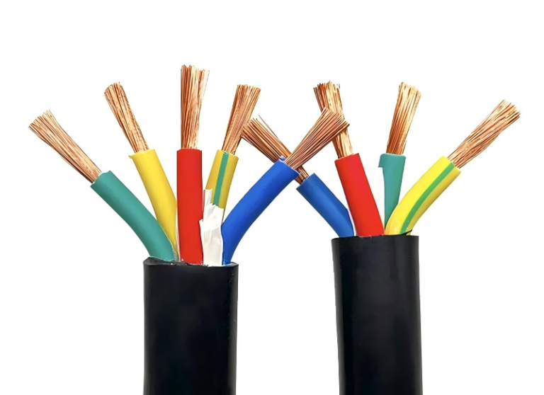
A medium voltage cable problem rarely starts with smoke; it starts with a voltage class guessed from an old drawing, a screen bonding detail missed in purchasing, or a sheath that dislikes the trench it was buried in. The plant sees nuisance trips, partial discharge risk, hot terminations, or a feeder outage that no maintenance team can fix quickly. The money leaves through shutdown hours, emergency cable pulls, failed tests, and drums of cable that cannot be used, so the practical answer begins with correct cable definition before price comparison.
A medium voltage cable is a shielded power cable used for distribution systems above low voltage and below transmission voltage, commonly covering IEC ratings from 3.6/6 kV to 26/35 kV and North American classes such as 5 kV, 15 kV, 25 kV, and 35 kV.
That simple definition hides most of the buying risk. The insulation system, conductor size, metallic screen, armor, sheath, fire behavior, test evidence, and drum logistics all decide whether the cable fits the switchgear room, the cable tray, the buried route, and the maintenance habits of the site.
Voltage classes and naming
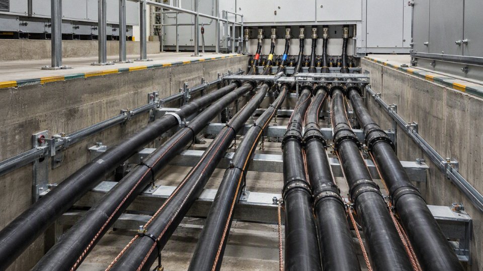
Voltage names are shorthand, not a complete cable specification. An IEC cable marked 8.7/15 kV and a North American “15 kV class” cable may serve similar networks, but they are named from different conventions and may differ in maximum system voltage, insulation level, test requirements, screen construction, and accepted fault-duty assumptions.
What U0/U and Um mean in IEC-style ratings
In IEC-style cable ratings, the notation normally appears as U0/U (Um):
- U0: rated power-frequency voltage between conductor and earth or metallic screen.
- U: rated power-frequency voltage between conductors.
- Um: highest system voltage for which the cable and associated equipment are intended.
For example, an 8.7/15 kV (17.5 kV) cable is rated for 8.7 kV conductor-to-earth, 15 kV conductor-to-conductor, with a highest system voltage of 17.5 kV. In a plant tender, that last number often gets missed because people read only “15 kV” and assume it matches every 15 kV switchboard. That is where procurement errors start.
Common IEC-style medium voltage ratings include:
| IEC-style cable rating | Typical highest system voltage, Um | Typical application area |
|---|---|---|
| 3.6/6 kV | 7.2 kV | 6 kV industrial and distribution systems |
| 6/10 kV | 12 kV | 10 kV public utility or plant distribution |
| 8.7/15 kV | 17.5 kV | 15 kV class systems in some IEC-based projects |
| 12/20 kV | 24 kV | 20 kV distribution networks |
| 18/30 kV | 36 kV | 30 kV distribution and industrial feeders |
| 26/35 kV | 40.5 kV | 35 kV networks where the specification calls for this insulation level |
Those are not universal substitution rules. Some specifications include 6/6 kV, 8.7/10 kV, or 21/35 kV depending on system earthing and the governing standard. The cable datasheet, project standard, and switchgear rating need to be read together, not line by line in isolation.
How IEC ratings compare with 5 kV, 15 kV, 25 kV, and 35 kV classes
North American practice often names medium voltage cable by voltage class: 5 kV, 15 kV, 25 kV, or 35 kV. That name usually sits inside a larger specification framework such as ICEA, AEIC, UL, CSA, or a utility’s own construction standard. The insulation may also be specified by insulation level, commonly expressed as 100%, 133%, or 173%, depending on system grounding and fault-clearing assumptions.
A rough market comparison looks like this:
| Market wording often seen in tenders | What must still be checked |
|---|---|
| 5 kV class | Insulation level, shield type, grounding condition, test standard |
| 15 kV class | Whether it aligns with 8.7/15 kV IEC practice, or a specific ICEA/AEIC construction |
| 25 kV class | Whether the network maximum voltage and BIL/impulse requirements match the cable system |
| 35 kV class | Whether the required construction corresponds to 21/35 kV, 26/35 kV, or a North American 35 kV class design |
The naming overlap is the trap. A buyer may receive two quotations that both say “35 kV cable,” with one based on IEC 26/35 kV and another based on a North American 35 kV class with a specified insulation percentage. Both may be legitimate in their own market. They are not automatically interchangeable.
A cable described only as '15 kV' is fully specified for procurement.False
The nominal voltage class does not define maximum system voltage, insulation level, earthing condition, test standard, screen design, or fault-duration assumptions. Those items must be stated or confirmed before purchase.
Voltage rating is not the same as operating voltage
A cable’s voltage rating is the declared capability of the cable design under a standard. The operating voltage is what the circuit normally runs at. Those two numbers are related, but they are not the same thing.
In practice, engineers have to separate several terms:
- Operating voltage: the normal service voltage of the feeder, such as an 11 kV motor feeder or a 13.8 kV plant distribution circuit.
- Rated voltage: the cable’s assigned U0/U or voltage class.
- Maximum system voltage: the upper limit the system equipment must tolerate continuously under normal service conditions.
- Insulation level: the insulation design basis, including thickness and stress control assumptions.
- Impulse withstand: the ability to withstand lightning or switching surges, usually tied to the system insulation coordination.
- Factory test voltage: the voltage applied during routine or type testing; it proves manufacturing integrity against the relevant standard but is not a service voltage.
The mechanism matters. Cable insulation is stressed by electric field between conductor and screen. If the conductor-to-earth voltage rises during an earth fault on an unearthed or impedance-earthed system, the insulation on healthy phases sees more stress than it would on a solidly earthed system. That stress may be temporary, but if protection allows long fault duration, insulation aging and partial discharge risk become less forgiving. This is one reason two cables with the same conductor size and similar outer diameter can have different acceptable applications.
There is also a commercial trade-off. Selecting a higher voltage grade can give more margin for fault behavior and future system changes, but it usually means a larger cable diameter, heavier drums, larger bending radius, more difficult termination work, and higher cost. On a crowded cable tray or in an old substation trench, the cheaper cable is not always the one that saves money after installation labor and accessories are counted.
Earthed and unearthed systems change the selection
On a solidly earthed system, an earth fault is normally cleared quickly and the conductor-to-earth voltage on healthy phases is controlled. On unearthed, resonant-earthed, or impedance-earthed systems, the healthy phases may experience elevated voltage to earth during a single-line-to-ground fault. If the protection philosophy allows continued operation under first earth fault, the cable insulation requirement can change.
This is not a paperwork detail. A mine, petrochemical site, offshore module, utility loop, or older industrial plant may keep running after a first earth fault to avoid process shutdown. That operating philosophy can push the specification toward a different insulation level than a simple nominal voltage reading would suggest. The same issue appears in plants where the earthing method has changed over the years but old cable schedules are copied into new procurement packages. I have seen that happen often enough that I no longer trust a voltage class until the grounding diagram and protection philosophy are checked.
Items to verify before locking the voltage grade:
- System nominal voltage and maximum system voltage, including transformer tap range.
- Earthing method, such as solidly earthed, resistance-earthed, impedance-earthed, resonant-earthed, or unearthed.
- Permitted earth-fault duration, especially whether operation continues after first fault.
- Applicable cable standard, not just the buyer’s familiar market name.
- Switchgear and termination compatibility, including voltage rating, creepage distance, screen treatment, and accessory standard.
- Utility or end-user rules, which may be stricter than the published cable standard.
- Consultant specification notes, because many projects embed voltage-class decisions in a general electrical design basis rather than in the cable schedule.
Specifying only “MV cable, 15 kV” or “35 kV XLPE cable” is not enough for a technically clean purchase order. The cable design must match the network earthing method, operating duty, fault behavior, impulse coordination, and the standard the receiving engineer will use for inspection.
Before approval, compare the cable datasheet against the local grid code, end-user electrical standard, engineering consultant requirements, and the switchgear documentation. The voltage class should be fixed only after those references agree; if they do not, resolve that conflict before drums are manufactured, not after the termination kit refuses to fit or the inspector rejects the routine test certificate.
Cable construction layers
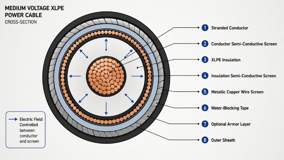
A medium voltage cable is not just “copper or aluminum plus insulation.” Its service life depends on how the conductor, semi-conductive screens, insulation, metallic screen, water blocking, armor, and sheath behave as one manufactured system under electrical stress, heat, moisture, pulling load, and fault current. In practice, the cheapest-looking layer on the datasheet can be the one that decides whether the cable lasts 30 years or fails after a few wet seasons.
Conductor: current capacity, losses, and handling
The conductor carries load current, but its influence goes beyond ampacity. Conductor material, shape, strand compaction, and DC resistance affect voltage drop, I²R losses, heating, pulling behavior, termination work, and the final cable outside diameter.
Common conductor choices include:
- Copper conductors
Copper gives lower resistance for the same cross-sectional area, which usually means lower losses and better voltage-drop performance. It is preferred where routes are long, load factors are high, space is tight, or terminations must stay compact. The trade-off is obvious to any buyer who has watched metal prices: copper raises upfront cost and drum weight. - Aluminum conductors
Aluminum is lighter and usually cheaper per installed ampere, but it needs a larger cross-section to match copper resistance. It can be a good choice for utility feeders, solar plants, wind farm collection systems, and long industrial routes where cable tray or duct space can accept the larger diameter. Termination discipline matters: aluminum lugs, joint compounds, oxide removal, and correct torque are not optional details. Stranded circular compacted conductors
These are common in medium voltage single-core and multi-core designs. Compaction reduces conductor diameter, improves roundness, and helps the extruded insulation system sit uniformly around the conductor. A poorly formed conductor surface makes the next layer work harder.Sector-shaped conductors
Sector conductors may appear in some multi-core power cable designs to reduce overall cable diameter and improve packing efficiency. They are not suitable for every medium voltage design or every standard, so the project specification and supplier construction data must be checked before assuming interchangeability with circular conductors.
Conductor resistance drives two costs at the same time: voltage drop during operation and heat generated inside the cable. Heat then feeds back into ampacity because insulation, sheath, soil thermal resistivity, grouping, ducts, and ambient temperature all limit how easily that heat escapes. A cable that looks economical at purchase can become expensive if the conductor is undersized for a high-load, high-duty-cycle plant.
Conductor screen: smoothing the first electrical interface
The conductor screen is a semi-conductive layer applied over the conductor before the main insulation. Its job is to remove sharp electrical stress points caused by strand edges, small gaps, and surface irregularities.
Without a proper conductor screen, the electric field would concentrate at high spots on the conductor surface. That concentration encourages partial discharge, insulation erosion, and premature failure. This is why medium voltage insulation systems are normally produced by controlled extrusion rather than assembled like low voltage cable.
In medium voltage cable, semi-conductive screens are electrical stress-control layers, not mechanical fillers.True
The conductor screen and insulation screen are designed to create smooth equipotential interfaces around the insulation, reducing local electric stress and partial discharge risk.
A practical procurement point: ask how the conductor screen, insulation, and insulation screen are applied. For many XLPE medium voltage cables, triple extrusion with clean material handling is preferred because it reduces contamination and interface defects between layers. The datasheet may say “XLPE insulated,” but the extrusion interface quality is where a lot of future reliability is either built in or lost.
Insulation: XLPE, EPR, and the project preference behind each
The insulation carries the voltage stress between conductor and earth. For most modern medium voltage power cables, the main choices are XLPE and EPR, with project preference shaped by thermal rating, flexibility, moisture exposure, installation method, and local utility or industrial standards.
XLPE insulation is widely used because it combines strong dielectric performance with good thermal capability. Typical XLPE medium voltage designs are often specified around 90 °C normal conductor operation, 130 °C emergency operation, and 250 °C short-circuit withstand, subject to the governing standard and the actual cable design. XLPE is relatively firm, dimensionally stable, and well suited to transmission, distribution, industrial feeders, mining infrastructure, renewables, and plant networks.
EPR insulation is generally more flexible and can tolerate bending and vibration better in some applications. It is often considered for movable equipment feeders, marine or offshore projects, mining cables, or installations where flexibility is valued. Depending on compound formulation and design, EPR may also offer favorable moisture behavior, but it is not a license to ignore water ingress, screen corrosion, or sheath damage.
The trade-off is not “XLPE good, EPR bad” or the reverse. XLPE often wins on broad availability, dielectric efficiency, and standard utility practice. EPR can win where handling flexibility and harsh service movement matter more. The conclusion stops holding when the end user’s specification mandates a particular insulation system, because compatibility with existing joints, terminations, qualification tests, and maintenance practice usually outweighs a theoretical material preference.
Insulation screen: controlling the field at the outside of insulation
The insulation screen is another semi-conductive layer, applied over the insulation. Together with the conductor screen, it creates a controlled, uniform electric field through the insulation wall.
This layer also provides the interface to the metallic screen. In service, the insulation screen must remain in intimate contact with the insulation, without voids, protrusions, contamination, or weak adhesion that interferes with stripping and termination. Cable jointers know the pain here: a screen that strips badly can turn a clean termination job into a risky repair, especially in a humid substation with dust blowing through the door.
For procurement, stripping behavior is worth asking about, especially for projects with many terminations. Some designs use bonded screens; others are easier-strip designs depending on standard, voltage class, and accessory requirements. The best choice depends on the termination system and installation skill available on site.
Metallic screen: fault path, shielding, and bonding behavior
The metallic screen sits over the insulation screen and performs several jobs at once. It provides an earth-fault current path, contributes to electromagnetic shielding, helps keep the cable surface at earth potential when correctly bonded, and can affect charging current, circulating current, and sheath voltage.
Common metallic screen designs include:
| Metallic screen type | Where it is commonly used | Main strengths | Watch points |
|---|---|---|---|
| Copper tape screen | Distribution and industrial MV cables | Good coverage, familiar construction | Limited fault current capacity unless designed with enough copper area |
| Copper wire screen | Feeders needing higher earth-fault current capacity or flexible screen design | Easier to size by copper area, good longitudinal conductivity | Screen wires must be protected from corrosion and mechanical damage |
| Aluminum laminate screen | Moisture barrier and shielding in some cable designs | Radial moisture resistance, compact construction | Fault capacity and connection method must be verified |
| Lead sheath | Harsh moisture or chemical environments, selected legacy or heavy-duty designs | Excellent radial moisture barrier, robust protection | Heavy, costly, environmental and handling concerns |
| Combined screen designs | Projects needing several functions at once | Can balance shielding, moisture barrier, and fault duty | Requires careful review of bonding and accessory compatibility |
Earth-fault current capacity is not a guess. It depends on prospective fault current, protection clearing time, screen material, cross-sectional area, bonding arrangement, and thermal limits. If a plant upgrades switchgear fault levels but leaves old cable screen assumptions untouched, the metallic screen can become the weak link during a fault.
Screen bonding also matters. Both-end bonding is simple but can create circulating currents in single-core AC cable systems. Single-point bonding or cross-bonding can reduce losses, but introduces sheath voltage management and link box requirements. This is one of those places where electrical design and cable procurement must talk before the purchase order is issued.
Fillers, binders, bedding, and tapes in multi-core cables
In a multi-core medium voltage cable, the spaces between insulated cores are not random voids. Fillers, binders, bedding layers, and separation tapes keep the cable round, stable, and manufacturable.
These layers help with:
- Cable geometry, keeping cores positioned evenly so the cable can be armored and sheathed without lumps or pressure points.
- Heat dissipation, because air gaps, loose fillers, and uneven bedding can change how heat travels from conductor to sheath.
- Mechanical stability, especially during pulling, bending, and cleating.
- Flame or water-blocking performance, when tapes or fillers are selected for those functions.
- Compatibility between materials, preventing sticking, chemical migration, or damage between adjacent layers.
Geometry is not just cosmetic. A lopsided three-core cable can be harder to gland, harder to terminate, and more prone to localized pressure during installation. In tray work, that becomes visible fast; in buried duct banks, the defect may not show until the cable has been thermally loaded for years.
Armor: mechanical protection without creating avoidable losses
Armor protects the cable against crushing, impact, rodent attack, pulling abuse, and installation damage. The correct armor depends on whether the cable is single-core or multi-core, AC or DC, buried or tray-mounted, and exposed to mechanical risk.
Typical armor options include:
- Steel wire armor
Common on multi-core cables where tensile strength and impact resistance are required. It performs well in direct burial and rough industrial sites. Steel tape armor
Often used where radial mechanical protection is needed but pulling tension is less severe. It is less flexible than wire armor and should be checked against the installation route.Aluminum wire armor
Used where non-magnetic armor is needed, especially on single-core AC cables. It avoids the severe induced heating problem that can occur with magnetic steel around single-core AC conductors.Other non-magnetic armor systems
These may include aluminum alloy or stainless non-magnetic constructions depending on project requirements and supplier capability.
The induced loss issue is not academic. A single-core AC cable surrounded by magnetic steel armor can behave like a heating system because the alternating magnetic field induces losses in the armor. For three-core cables, the magnetic fields largely balance within the cable, so steel armor is usually much less problematic. Always verify the exact design against the applicable cable standard and manufacturer data.
Outer sheath: the plant environment’s first line of defense
The outer sheath protects the cable from the installation environment. It sees sunlight, oil mist, wet soil, concrete alkalinity, insects, abrasion, cleaning chemicals, flame exposure, and the occasional forklift mistake. No insulation system survives long if the sheath lets the wrong environment reach the inner layers.
Common sheath materials include:
- PVC, widely used, economical, and available in flame-retardant grades, though not the best choice for every low-smoke or harsh chemical requirement.
- PE, with good moisture resistance and toughness, often used for buried or outdoor cables.
- HDPE, selected where higher abrasion resistance and mechanical toughness are needed.
- LSZH compounds, used where low smoke and halogen-free performance is required, such as tunnels, public infrastructure, offshore areas, and enclosed buildings.
- Specialized flame-retardant, oil-resistant, termite-resistant, UV-resistant, or low-temperature compounds, specified when the environment justifies them.
Sheath selection is a classic trade-off. A tough PE or HDPE sheath may suit a buried feeder but may not satisfy flame or smoke requirements inside a building. LSZH may satisfy fire performance needs but can require closer review of abrasion, moisture exposure, and installation temperature. The preferred sheath flips when the cable crosses from outdoor buried route to indoor escape path, which is why route segmentation matters in cable schedules.
Water blocking and moisture barriers
Water does not need to flood a cable to damage it. Moisture can enter through sheath cuts, poor glands, damaged joints, or long-term exposure at cable ends left uncapped in the yard. Once inside, water can migrate along the cable and accelerate corrosion, screen degradation, and insulation aging depending on construction and operating stress.
Water protection may include:
- Longitudinal water blocking, using swelling tapes, swelling yarns, or swelling powder to restrict water travel along the cable.
- Radial moisture barriers, such as aluminum laminate or lead sheath, to resist moisture entering through the sheath wall.
- Water-blocked conductor designs, used where water migration through conductor interstices must be controlled.
- Water-resistant sheath systems, selected for wet soil, ducts, coastal sites, or submerged-risk installations.
Swelling materials work by expanding when exposed to water, filling internal pathways and slowing migration. They do not repair a damaged sheath or make poor joints acceptable. For direct-buried routes, flood-prone duct banks, renewable projects in agricultural land, and coastal plants, water blocking should be discussed before quotation, not after a failure investigation.
The expensive visible items — conductor metal, insulation material, armor — deserve attention, but they are not the whole cable. A poor semi-conductive screen, contaminated extrusion interface, undersized metallic screen, incompatible sheath, or missing moisture barrier can shorten service life even when the headline materials look correct. A serious cable review follows the full layer stack from conductor to sheath and checks whether each layer fits the fault duty, installation route, termination system, environment, and maintenance reality of the site.
Main cable types
Medium voltage cable types are best separated by how they are built, where they are installed, and what operating duty they must survive. In procurement, the product name is less reliable than the engineering description: voltage rating, conductor, insulation, metallic screen, armor, sheath, installation environment, and test regime decide whether a cable is suitable.
Single-core vs three-core medium voltage cables
Single-core cables give more routing flexibility and usually better ampacity control, while three-core cables reduce the number of individual runs and terminations. The choice often comes down to space, installation labor, magnetic field management, screen bonding, and how the cable will be pulled through trenches, ducts, trays, or risers.
In a single-core system, each phase is a separate cable. That helps on long routes and large conductor sizes because each cable is lighter, easier to bend, and easier to place in trefoil or flat formation. It also lets the designer space phases for thermal reasons, although too much spacing can increase magnetic field effects and induced voltages in metallic screens. On high-current circuits, screen bonding becomes a serious design item, not a detail left to the jointing crew. Single-point bonding, both-end bonding, and cross-bonding each affect circulating current, sheath voltage, fault behavior, and accessory selection.
Three-core medium voltage cables place all three phase cores inside one common outer sheath, often with shared bedding and armor. The magnetic fields tend to cancel better inside the cable assembly, so screen and armor losses are usually easier to control. The trade-off is physical size and stiffness. A three-core 15 kV or 35 kV class cable with armor can be a stubborn item in a tight substation basement; pulling tension, sidewall pressure, and bend radius need checking before the drum arrives on site.
| Selection point | Single-core cable | Three-core cable |
|---|---|---|
| Installation space | Needs three separate phase paths or controlled formation | One cable route, often neater in trenches and risers |
| Bending and handling | Easier per cable, especially at larger sizes | Heavier and stiffer as size increases |
| Magnetic behavior | Formation and bonding strongly affect losses | Phase grouping helps field cancellation |
| Terminations | More individual cable ends to prepare | Fewer cable bodies, but larger terminations |
| Current rating | Can be favorable if spacing and bonding are well designed | Often limited by combined thermal mass and installation conditions |
A current rating from a catalogue is not a plant rating until the installation method, grouping, soil or air temperature, bonding system, and load profile are known. This is where many tender comparisons go wrong: one supplier quotes an optimistic free-air value, another quotes buried duct conditions, and the two numbers look like a product difference when they are actually a calculation-basis difference.
Armored and unarmored designs
Armored cable is selected when the route can damage the cable; unarmored cable is selected when the installation already provides mechanical protection. Direct burial, industrial yards, mining areas, exposed tray routes, and road crossings often justify armor. Clean cable trenches, indoor switchgear rooms, protected ducts, and controlled utility tunnels may not.
Armor can be steel wire, steel tape, aluminum wire, or other constructions depending on whether the cable is single-core or three-core, the fault current path, corrosion exposure, and pulling requirements. For AC single-core cables, magnetic armor materials can create additional losses if applied incorrectly, so non-magnetic armor is often considered. This is a good example of a mechanical choice becoming an electrical issue.
Armoring improves resistance against impact, rodents, digging damage, dragging, and site abuse, but it adds cost, diameter, weight, and termination work. It can also make delivery logistics less forgiving. A large armored drum may not fit the unloading area a civil contractor left behind, which sounds trivial until a crane is booked twice and the cable sits in the rain with damaged lagging.
Underground distribution and network cables
Underground medium voltage distribution cables are the normal choice for utilities, industrial parks, substations, commercial infrastructure, and municipal grids where reliability and protected routing matter. They are usually fully screened power cables designed to control the electric field within the insulation system and safely carry charging current, fault current, and induced sheath effects under defined conditions.
Typical applications include:
- Utility feeders from primary substations to ring main units or distribution transformers.
- Industrial plant feeders to motor control centers, process substations, compressors, furnaces, or pumping stations.
- Commercial infrastructure such as hospitals, campuses, airports, malls, and district energy systems.
- Municipal grid reinforcement where overhead lines face permitting, weather, or space limits.
For underground routes, the cable is only one part of the system. Joint quality, duct fill, pulling lubricant, trench thermal resistivity, backfill compaction, and water migration can dominate service life. In practice, I like to see route drawings and pulling sections before approving a conductor size on a long feeder; otherwise the electrical design may be right and the installation method wrong.
Overhead covered conductors and aerial bundled systems
Overhead covered medium voltage conductors are not the same product family as fully shielded underground medium voltage cables. Covered conductors are used on pole lines to reduce contact faults from vegetation, wildlife, windborne debris, or phase clashing, but they usually do not have the same metallic screen and controlled radial electric field structure as underground power cables.
Aerial bundled or spacer cable systems can be useful where bare overhead lines are vulnerable but undergrounding is too expensive or disruptive. They suit rural feeders, urban edge networks, forested routes, and retrofit corridors with limited right-of-way. The limitation is that accessories, clearances, lightning protection, pole loading, and local utility practice govern the design. A buyer should not substitute an aerial covered conductor for an underground XLPE power cable just because both carry a similar voltage class.
Submarine and water-crossing cables
Submarine and water-crossing medium voltage cables are engineered around water exclusion, tensile load, installation risk, and repair difficulty. The cable may need longitudinal water-blocking, radial moisture barriers, heavy armor, fiber optic elements, or special serving layers depending on route depth, current, seabed or riverbed conditions, vessel method, and expected external aggression.
A short river crossing for an industrial intake line is not the same as an offshore wind export or inter-array cable. Pulling through a horizontal directional drilled duct creates different loads than laying from a vessel. Armor must handle installation tension and post-installation threats such as abrasion, anchors, fishing gear, rocks, or river movement. Once submerged, a defect is expensive to locate and more expensive to repair, so factory test records, drum handling, end sealing, and route engineering deserve more scrutiny than they sometimes receive in low-bid tenders.
Renewable energy and collector system cables
Wind farms, solar plants, battery energy storage sites, and hybrid renewable projects use medium voltage cables mainly for collector circuits and feeders. Long route lengths, cyclic generation, distributed inverter or turbine sources, and large site footprints make losses, voltage drop, sheath bonding, and logistics commercially important.
Solar collector cables may see high daytime loading followed by cooling cycles, while wind circuits can experience variable loading, frequent output changes, and remote terrain installation. Energy storage plants can have rapid charge and discharge profiles depending on grid service duty. The mechanism is simple: thermal cycling expands and contracts conductors, insulation, screens, and accessories at different rates; poor jointing, loose terminations, or unsuitable accessories suffer first. The preferred cable may change when trench thermal conditions are poor or when the project has long radial circuits, because a larger conductor can reduce losses enough to pay for itself over time.
Mining, tunneling, and heavy industrial duty cables
Mining, tunneling, ports, steel plants, cement works, petrochemical sites, and large workshops often value mechanical survival as much as electrical rating. Flexible medium voltage cables, reeling cables, trailing cables, or heavy-duty industrial feeders may need abrasion-resistant sheaths, oil resistance, flame performance, crush resistance, and tolerance for vibration or mechanical shock.
The operating abuse is different from a buried utility feeder. Cables may be dragged, run over, splashed with oil, exposed to slurry, bent around temporary structures, or moved during equipment relocation. In those cases, a standard unarmored distribution cable can fail for reasons that have little to do with insulation design. Sheath compound, reinforcement, minimum bend radius, gland system, and repair procedure become procurement items.
Critical infrastructure applications
Railway, metro, airport, data center, hospital, tunnel, and other critical infrastructure projects often impose stricter requirements on flame spread, smoke emission, halogen content, circuit integrity, reliability, and documentation. The exact requirement depends on local codes, project specifications, evacuation philosophy, and equipment served.
Common buyer checks include:
- Low-smoke, halogen-free sheath requirements where people may be exposed to fire smoke.
- Flame retardant or fire-resistant performance where circuits must continue operating for a defined period.
- Compatibility with switchgear, transformers, protection settings, and earthing systems.
- Proven accessory systems for joints, terminations, glands, and bonding leads.
- Type test evidence and routine test records tied to the offered cable construction, not a vaguely similar product.
A medium voltage cable should be specified by its rating, construction, installation environment, and applicable test regime rather than by product nickname alone.True
Trade names and regional cable codes vary by market. Engineering classification reduces the risk of comparing unlike constructions or accepting a cable that matches the name but not the duty.
Product names vary across IEC-based markets, North American practice, utility specifications, and manufacturer catalogues. A cable called “MV armored XLPE” may still differ in conductor class, screen area, water blocking, sheath compound, fire behavior, and test evidence. Classify the duty first, then match the product family; the catalogue name should confirm the specification, not replace it.
Selection criteria
A medium voltage cable should be selected from the electrical system outward: voltage, fault duty, load, installation route, environment, fire behavior, accessories, and logistics all have to agree. The cheapest compliant-looking cable on a quotation is often not the lowest-cost cable in service if its ampacity assumptions, screen rating, pulling limits, or accessory scope are wrong.
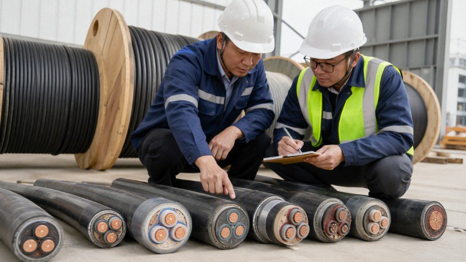
Start with system data, not cable catalogues
The first specification page should describe the system the cable must survive, not just the cable the buyer wants priced. A supplier can quote a cable from “15 kV, 3-core, copper, XLPE” wording, but that is not enough to confirm thermal rating, earth-fault performance, voltage stress, installation suitability, or accessory compatibility.
Collect these inputs before sizing:
- Nominal voltage and maximum system voltage
- State the normal system voltage and the highest system voltage used by the governing standard.
- Do not mix IEC-style ratings and North American voltage classes without checking equivalence. A cable name that sounds close may not have the same insulation level or test basis.
- Frequency
- Most projects are 50 Hz or 60 Hz, but this still belongs in the data sheet.
- Frequency affects reactance, screen losses, and induced voltage behavior, especially on longer routes and single-core cable systems.
- System earthing method
- Solidly earthed, resistance-earthed, isolated, and resonant-earthed systems impose different earth-fault voltage and current duties.
- This affects insulation stress during faults and the metallic screen cross-section.
- Fault current and fault duration
- Give both phase fault and earth fault values.
- Protection clearing time matters as much as current. A 1-second duty and a 3-second duty are not the same cable screen or conductor problem.
- Load profile
- Provide continuous load, cyclic peaks, emergency loading expectations, seasonal variations, and whether the cable feeds motors, transformers, furnaces, drives, or mixed distribution.
- Typical XLPE medium voltage cables are often designed around 90 °C normal conductor operation, 130 °C emergency operation, and 250 °C short-circuit withstand, but the actual permitted values depend on the standard and project specification.
- Harmonics and load quality
- Variable frequency drives, arc furnaces, rectifiers, and some renewable power systems can create heating and screen current effects that a simple 50 Hz steady-load calculation misses.
- Harmonic content does not automatically disqualify a cable design, but it should be declared before ampacity is finalized.
- Future load growth
- State whether the route is being sized for present load only, a planned expansion, or a spare-capacity philosophy.
- Future capacity added after civil works are complete is usually expensive; oversized copper bought unnecessarily is also expensive. The better answer depends on the project’s expansion probability, not optimism.
Select conductor material and cross-sectional area
Conductor sizing is a balance between ampacity, voltage drop, fault withstand, losses, installation force, and money. Copper gives lower resistance in a smaller diameter; aluminum is lighter and usually cheaper per ampere, but requires larger cross-section, correct termination practice, and attention to joint quality.
The usual decision checks are:
| Check | What it controls | Practical plant-floor issue |
|---|---|---|
| Ampacity | Normal thermal operation | Overheating accelerates insulation aging and may force derating after commissioning |
| Voltage drop | Delivered voltage at load | Long feeder runs to pump houses, mines, ports, or solar collection points can fail here before ampacity fails |
| Short-circuit withstand | Thermal survival during faults | Conductor area must tolerate fault energy until protection clears |
| Installation method | Heat dissipation and mechanical handling | Same cable behaves differently in free air, duct bank, direct burial, tray, or tunnel |
| Pulling tension | Installability | Long duct pulls can exceed conductor or sidewall pressure limits before the route is complete |
| Loss cost | Operating expense | Higher conductor cost may be justified on high-load, long-hour feeders |
| Accessory size | Terminations, joints, glands, cleats | Large conductors increase termination space, bend radius, and installation labor |
The mechanism is straightforward but often underestimated: conductor resistance creates heat, heat raises conductor temperature, and higher temperature raises resistance again. If the surrounding soil, duct, or air cannot remove that heat, the cable must be derated or upsized. On a lightly loaded standby feeder, loss savings may never repay extra metal; on a 24-hour process feeder running near capacity, losses can dominate the lifecycle cost discussion.
A larger medium voltage conductor always makes installation easier because it runs cooler.False
Upsizing can reduce resistance losses and operating temperature, but it also increases cable diameter, weight, bending radius, pulling tension, accessory size, drum weight, and sometimes short-circuit mechanical forces.
This is the counter-intuitive procurement trap. A larger conductor may be electrically attractive and commercially painful. It can require bigger drums, different trailers, a larger cable winch, wider trench handling clearance, bigger bending sweeps into switchgear, larger lugs, larger glands, and stronger cleating under fault forces. In retrofit work, I have seen the switchgear cable box become the limiting item, not the cable ampacity calculation.
Choose insulation type and thickness
Insulation selection should follow the voltage class, applicable standard, operating temperature, dielectric performance requirements, route environment, and required flexibility. XLPE is the common workhorse for modern medium voltage distribution because it offers good thermal capability and dielectric strength, but the exact compound, semiconductive interfaces, cleanliness, and manufacturing control matter.
Insulation thickness is not a buyer’s personal preference item. It is tied to the standard, rated voltage, insulation level, and sometimes earthing condition. Thicker insulation can improve voltage stress margin, but it also increases diameter, stiffness, bending radius, joint size, and heat path from conductor to environment. That trade-off matters on high-current circuits where thermal performance is already tight.
Specify insulation with enough detail to avoid ambiguity:
- governing standard and voltage designation;
- insulation material, usually XLPE or another specified system where applicable;
- rated conductor temperature for normal and emergency operation;
- short-circuit temperature basis;
- insulation screen and conductor screen requirements;
- water-tree resistance expectations where wet service is a concern;
- compatibility with required terminations, joints, and separable connectors.
The conclusion stops holding when the cable is part of a special duty system: subsea export, mining trailing duty, railway, nuclear, fire-survival circuits, or very high harmonic industrial feeders can impose requirements outside a standard utility-style XLPE selection.
Define metallic screen and bonding design
The metallic screen is not decorative copper. It provides an earth fault current path, controls electric field behavior with the insulation screen, helps electromagnetic compatibility, and influences induced voltages and circulating currents.
For procurement, define both the screen construction and the screen cross-sectional area. Typical options include copper wire screen, copper tape screen, lead alloy sheath in some specialized applications, or combinations depending on standard and service environment. The right choice depends on fault duty, corrosion exposure, flexibility, water blocking strategy, and bonding method.
Key screen decisions:
- Earth-fault current capacity
- The screen must withstand the specified earth fault current for the protection clearing time.
- Do not let a catalogue default screen area pass unexamined on resistance-earthed or high-fault systems.
- Bonding method
- Both-ends bonding is simple but can create circulating currents and losses in single-core systems.
- Single-point bonding reduces circulating current but introduces standing induced voltage.
- Cross-bonding is used on longer routes to control sheath voltage and losses, but it needs correct link boxes, sectional lengths, and maintenance discipline.
- Touch voltage and induced voltage
- Long single-core runs can produce sheath voltages that are unpleasant at best and dangerous at worst.
- The bonding design must be checked against the project safety rules and current standards, not guessed from a previous job.
- Electromagnetic compatibility
- Sensitive control cables, communication systems, rail signaling, or instrumentation near the route may require tighter control of magnetic fields and induced noise.
- Cable formation, phase spacing, trefoil versus flat arrangement, and screen bonding all affect the result.
This is one place where “same cable, different installation” can mean different losses and different safety behavior.
Select sheath and armor for the route
The outer system should be selected for where the cable will live, not just how it looks on a datasheet. Direct burial, concrete duct banks, cable trays, tunnels, marine exposure, chemical plants, refineries, mines, and urban substations all attack cables differently.
Use the route conditions to choose sheath and armor:
- Direct burial
- Needs moisture resistance, mechanical protection, and compatibility with backfill.
- Armor or other mechanical protection may be required where stones, settlement, third-party digging, or rodents are credible risks.
- Ducts and duct banks
- Pulling friction, duct fill, water accumulation, and heat dissipation become major issues.
- A smooth sheath may help installation, but thermal derating in congested ducts can be severe.
- Cable trays and tunnels
- Sunlight, flame spread, smoke behavior, cleating, and ventilation matter.
- UV-resistant sheath may be needed outdoors. In tunnels, smoke and acid gas limits can drive material choice.
- Industrial chemical exposure
- Oils, solvents, acids, alkalis, process water, and washdown chemicals should be declared.
- PVC, PE, LSZH, and specialty sheath compounds do not behave the same in every chemical environment.
- Rodent, termite, and impact risk
- Steel wire armor, steel tape armor, aluminum wire armor for single-core applications, or non-metallic protection may be considered depending on magnetic effects and installation rules.
- For single-core AC cables, ferromagnetic armor can cause heating problems if selected carelessly.
- Moisture and water blocking
- Wet soil, high water table, tunnels with seepage, and ducts that behave like drains may justify longitudinal or radial water barriers.
- The cost is easier to defend before installation than after a failed sheath test.
Account for installation environment and derating
Ampacity tables are only as good as their assumptions. Soil thermal resistivity, burial depth, duct arrangement, air temperature, cable grouping, tray loading, ventilation, and nearby heat sources can change the allowable current enough to alter conductor size.
The common derating inputs are:
- soil thermal resistivity, including seasonal drying near loaded cables;
- ambient ground and air temperature;
- burial depth and trench geometry;
- duct material, duct spacing, and concrete encasement;
- number of loaded circuits in the same bank or tray;
- cable spacing and formation;
- ventilation in tunnels, basements, and enclosed risers;
- proximity to steam lines, furnaces, hot process piping, roofs, or solar-heated structures;
- backfill quality and compaction;
- whether spare ducts will later receive energized cables.
In practice, soil data is often weak. Someone copies a default value, the civil contractor uses whatever backfill is available, and the electrical team inherits a thermal bottleneck for 30 years. If the feeder is heavily loaded or difficult to replace, pay for a proper route thermal review and specify thermal backfill where needed. The extra civil control can be cheaper than moving up one or two conductor sizes across several kilometers.
Check fire performance and emergency behavior
Fire requirements should be written as performance requirements, not vague words like “fireproof cable.” Different projects need different behavior: flame retardancy, low smoke zero halogen performance, acid gas limits, reduced toxicity, or circuit integrity during fire.
Clarify which of these applies:
- Flame retardancy
- Limits flame propagation along the cable under defined test conditions.
- Useful for trays, tunnels, substations, buildings, and grouped cable routes.
- Low smoke zero halogen behavior
- Reduces corrosive and dense smoke compared with halogenated materials.
- Often required in tunnels, transport systems, occupied buildings, data centers, and enclosed industrial areas.
- Acid gas and smoke density limits
- Protect people, switchgear, electronics, and emergency response visibility.
- Must be tied to the applicable standard and test method.
- Circuit integrity
- Required where the cable must keep supplying emergency systems during fire.
- This is a specialized requirement and may change cable construction, accessory choice, support spacing, and installation method.
Do not specify the most severe fire package by habit. LSZH compounds and fire-resisting constructions can cost more, handle differently, and may have different mechanical or moisture characteristics. Use them where the risk assessment and local code demand them.
Consider accessories before the cable is ordered
Terminations, joints, separable connectors, stress control systems, lugs, glands, cleats, link boxes, surge arresters, and earthing kits should be selected alongside the cable. Leaving accessories until installation is how projects end up with beautiful cable drums and no practical way to connect them.
Check accessory compatibility against:
- cable voltage rating and insulation diameter;
- conductor material, shape, and size;
- screen type and screen cross-section;
- armor type and gland requirements;
- sheath diameter and jacket material;
- indoor, outdoor, plug-in, or GIS termination interface;
- pollution level, altitude, and humidity;
- available cable box space and bending radius;
- earthing and bonding arrangement;
- test requirements after installation.
A small mismatch can become expensive. For example, changing from aluminum to copper or from compacted round to sector conductor may affect lug selection. Changing insulation diameter can move a termination kit out of its range. Increasing conductor size may push bending radius beyond the switchgear plinth layout. None of these problems are exotic; they are normal project coordination failures.
Document assumptions so the quotation is buildable
A technically sound cable can still fail commercially if the RFQ leaves out route conditions, accessories, testing, packing, or delivery constraints. Procurement should force the assumptions into writing before bids are compared, because suppliers otherwise price different scopes under the same line item.
At minimum, document:
- rated voltage and applicable standard;
- conductor material, size, and construction;
- insulation system and temperature rating;
- metallic screen type, area, and bonding design basis;
- armor and sheath material;
- fire performance requirements;
- installation method and route environment;
- soil thermal resistivity, ambient temperature, grouping, and burial depth assumptions;
- required accessories and quantities;
- type test evidence and routine test records required with supply;
- drum length limits, maximum drum weight, lifting method, and storage conditions;
- packing, marking, shipping route, and delivery schedule;
- site testing and inspection responsibilities;
- deviations allowed and deviations requiring written approval.
Bid comparison should then separate base cable price from accessories, special testing, packing, freight, documentation, and optional route-specific upgrades. That is less exciting than arguing over copper price, but it is where many medium voltage cable projects either stay controlled or quietly become claims, delays, and emergency substitutions.
Standards and testing
A medium voltage cable is only as credible as the standard, construction, and test evidence behind it. For project buyers, the useful question is not “does the quotation mention IEC or ICEA?” but “which exact cable design was tested, which production length was routine-tested, and which documents prove it?”
International projects commonly reference several standard families, and they are not interchangeable line by line. IEC standards are widely used for power cables in export projects, with medium voltage classes such as 3.6/6 kV through 26/35 kV. British, German, North American, Australian, and utility specifications may use different voltage notation, test sequences, material assumptions, or accessory compatibility requirements.
Common reference families include:
- IEC: widely used for extruded medium voltage power cables, test methods, conductor requirements, flame tests, and related electrical performance requirements.
- BS and BS EN: often aligned with European practice, but still specified directly in parts of the Middle East, Africa, and Commonwealth-linked projects.
- VDE and DIN VDE: common in German-influenced specifications, particularly where conservative construction and documented testing are expected.
- ICEA: frequently seen in North American-style medium voltage cable specifications, especially for utility, industrial, and distribution cable designs.
- AEIC: often used by electric utilities for qualification requirements and performance expectations beyond a simple catalogue cable description.
- ASTM: typically used for material-related requirements, such as conductor metal properties, polymer test methods, or mechanical testing references.
- AS/NZS: used in Australia, New Zealand, and projects influenced by those procurement systems.
- Project-specific utility standards: sometimes stricter than the public standard, especially on water blocking, screen construction, jacket properties, packaging, type approval, and documentation.
The mistake I see in tender comparisons is treating all of these as labels on the same product. They are not. A cable offered as “IEC standard” may differ from an ICEA-style cable in insulation thickness, metallic screen design, jacket compound, test regime, and how the cable is intended to be terminated.
Design standards, material standards, fire standards, test methods, and specifications are different tools
A proper medium voltage cable specification usually pulls from more than one category of document. Mixing them up creates procurement gaps that only show up after the cable is delivered, or worse, after installation.
| Document type | What it controls | Typical buying risk if unclear |
|---|---|---|
| Design standard | Rated voltage, construction rules, insulation level, electrical tests | Cable may be correctly tested, but not for the system duty intended |
| Material standard | Conductor, insulation, semiconductive layers, sheath or jacket compounds | Substitution may pass basic inspection but age poorly in service |
| Fire performance standard | Flame spread, smoke, halogen acid gas, circuit integrity where applicable | Indoor, tunnel, or public-infrastructure projects may fail acceptance |
| Test method standard | How a property is measured, not always what value is required | Supplier and buyer may quote different results from different methods |
| Customer technical specification | Project-specific requirements beyond public standards | Low bidder may exclude armor, water blocking, sheath color, marking, or special packing |
Compliance is not a sentence in a quotation; it is a chain connecting the specified design, the manufactured drum, and the test evidence. A quotation that lists five standards but does not confirm rated voltage, conductor, insulation system, screen, armor, sheath, test scope, and acceptance criteria is still incomplete.
Type tests prove the design, not every drum
Type tests are qualification tests performed on a representative cable design to show that the design can meet the governing standard. They are usually costly, time-consuming, and not repeated for every production batch unless the design changes or the customer specifically requires retesting.
For medium voltage XLPE cable, type testing can include:
- Electrical tests
- AC voltage withstand
- Partial discharge performance
- Impulse voltage withstand
- Tan delta or dielectric loss where specified
- Heating cycle voltage tests in some qualification regimes
- Thermal and aging tests
- Long-term heat exposure of insulation and sheath materials
- Compatibility checks between insulation, semiconductive screens, tapes, fillers, and jacket compounds
- Hot set testing for cross-linked insulation
- Shrinkage checks where required
- Mechanical and dimensional tests
- Insulation and sheath thickness
- Tensile strength and elongation before and after aging
- Bending or handling-related checks where the standard calls for them
- Armor, screen, and conductor dimensional verification
- Environmental or construction-specific tests
- Water penetration for longitudinally water-blocked designs
- Flame performance for specified low-smoke, halogen-free, or fire-retardant cables
- Jacket resistance to abrasion, oil, UV, or chemicals where required by the project
The mechanism is straightforward: type tests stress the cable design beyond ordinary service conditions to expose weak interfaces, unsuitable compounds, poor cross-linking, or incompatible materials before a project depends on them. A cable can look excellent on a drum and still fail a heating-cycle or aging sequence if the insulation shield interface, compound selection, or cure profile is wrong.
The trade-off is time and cost. Full type test evidence gives stronger assurance, but arranging fresh type tests for every small order can delay procurement by weeks or months. For repeat designs from an established factory, buyers often accept valid previous type test reports if the construction, materials, voltage class, and standard edition match the project requirement. That acceptance stops being sound when the supplier changes compound source, screen construction, insulation thickness, conductor design, or manufacturing process.
Routine tests are the buyer’s first proof that each manufactured length was checked
Routine tests are performed on manufactured cable lengths, usually every drum or production length depending on the governing standard. They are not a substitute for type tests, but they are the closest evidence that the cable shipped to site was electrically screened before dispatch.
Typical routine tests include:
- Conductor resistance
- Confirms the conductor size and conductivity are within the required limit.
- A high value can indicate undersized conductor, wrong material, poor stranding, or temperature correction errors.
- Voltage withstand test
- Applies a specified high voltage to verify insulation integrity.
- It catches gross insulation defects, handling damage, and some manufacturing flaws, but it does not prove long-term aging performance by itself.
- Partial discharge test where required
- Critical for many medium voltage insulation systems.
- Acceptance levels and test voltage depend on the standard and cable rating, so the buyer should not assume one universal limit.
- Sheath or jacket integrity checks
- Used especially where metallic screens, armor, or buried service are involved.
- Depending on the standard and construction, this may include DC sheath testing or spark testing during production.
- Marking, length, and drum verification
- Confirms the delivered cable matches the purchase order and packing list.
- This sounds basic until a shutdown crew opens a drum and finds the wrong length for a tray run.
Routine test reports should identify the order, cable type, rated voltage, conductor size, drum number, length, test voltage, measured values, acceptance criteria, test date, and responsible inspection authority. If the report only says “passed” with no measured data, I would treat it as weak evidence.
A quotation that names a cable standard does not prove that the quoted cable construction has been type-tested or that every shipped drum will receive the required routine tests.True
Standards define requirements, but the buyer still needs the exact construction, applicable clauses, production test records, and traceability documents to verify compliance for the supplied cable.
Sample tests and special tests close the gap between design approval and production reality
Sample tests are usually taken from production lengths or batches to confirm construction and material properties. They sit between type tests and routine tests: less exhaustive than full design qualification, but more physical and construction-focused than a simple voltage test.
Important sample and special tests can include:
- Insulation thickness and eccentricity
- Thin spots raise electrical stress locally.
- Eccentric insulation also complicates accessory installation because the prepared insulation diameter varies.
- Sheath thickness
- Affects mechanical protection, moisture resistance, and abrasion life.
- Too thin a sheath may not fail the factory voltage test but can be damaged during pulling or backfilling.
- Hot set test
- Checks the cross-linking state of XLPE insulation.
- Poor cross-linking can lead to deformation under heat and mechanical stress.
- Tensile strength and elongation
- Used for insulation and sheath compounds before and after aging.
- Low elongation after aging is a warning for cracking risk, especially in cold climates or high-vibration installations.
- Screen resistance
- Important where metallic screen fault-current duty, bonding arrangement, or circulating losses matter.
- This should be checked against the project’s earthing and protection design, not guessed from catalogue wording.
- Water penetration
- Relevant for water-blocked cables in wet ducts, direct burial, coastal sites, and utility networks.
- The test arrangement must match the specified longitudinal or radial water-blocking requirement.
- Dimensional checks
- Include conductor diameter, insulation diameter, overall diameter, armor dimensions, and finished cable ovality.
- These affect glands, cleats, trays, pulling calculations, and termination kit selection.
Special tests are often negotiated in the inspection and test plan. A buyer may ask for witnessed partial discharge testing, additional sheath testing, drum-by-drum dimensional checks, or third-party inspection. That extra assurance has a cost, but on a mine feeder, refinery shutdown, wind farm collector system, or utility interconnection, the cost is usually smaller than one failed energization.
Why partial discharge deserves special attention
Partial discharge is one of the most useful quality indicators for medium voltage insulation because it exposes small internal defects that may not break down immediately. Voids, protrusions, contamination particles, poor semiconductive screen contact, or rough insulation interfaces can create local electric stress concentrations. Under service voltage, those tiny discharge sites can erode polymer insulation over time.
The factory controls that matter are not glamorous, but they decide the result:
- Clean handling of XLPE and semiconductive compounds
- Dry, contamination-controlled material feeding
- Stable triple-layer extrusion of conductor screen, insulation, and insulation screen
- Smooth interfaces between semiconductive layers and insulation
- Controlled cross-linking and cooling
- Online diameter and eccentricity monitoring
- High-voltage and partial discharge test equipment with valid calibration
Triple-layer extrusion is important because it forms the conductor screen, insulation, and insulation screen in one coordinated process, reducing interface contamination and improving adhesion consistency. If layers are applied separately or the material path is dirty, the interface can become the weak point even when the insulation material itself is good. In practice, this is where a tidy factory and disciplined operators matter as much as the catalogue.
The trade-off is that very tight process control increases manufacturing discipline, scrap control effort, and quality cost. Cheaper supply often hides those costs by reducing inspection, accepting wider dimensional variation, or relying on final voltage withstand alone. For low-criticality temporary cable that may be acceptable if the specification allows it; for permanent medium voltage distribution, it is a poor place to save money.
Factory acceptance documents should be specific enough to audit
A qualified supply package should make the cable traceable from raw material to shipped drum. For international projects, the useful factory acceptance package normally includes:
- Certificate of conformity against the agreed standard and purchase specification
- Type test reports for the same or clearly equivalent cable design
- Routine test reports for each manufactured drum or length
- Sample test reports where required by the standard or inspection plan
- Material traceability for conductor, insulation, semiconductive compounds, sheath, armor, and tapes where applicable
- Drum list with drum number, cable type, rated voltage, size, length, gross weight, net weight, and destination marking
- Inspection and test plan showing hold points, witness points, and acceptance criteria
- Calibration records for key test equipment when requested
- Packing photos, drum protection details, and shipping marks
- Third-party inspection reports if the contract requires witnessed testing
For a manufacturer such as Jinda, with integrated R&D, production, sales, technical support, and after-sales service across multiple production bases, the procurement discussion should still come down to the same evidence package: exact construction, applicable standard, test scope, and traceable documents. Scale helps only when the factory systems convert it into repeatable extrusion quality, controlled testing, and disciplined shipment records.
A practical buyer’s rule is simple: ask the supplier to map every compliance claim to a document, a test, or a construction feature. If a listed standard cannot be tied to the cable design, production test record, or material requirement, it is not yet evidence.
Installation and operation
A medium voltage cable that left the factory in perfect condition can still fail early if the installation changes its thermal environment, damages the sheath, or disturbs the insulation screen interface. In practice, many MV cable faults trace back not to the conductor or XLPE compound, but to pulling abuse, poor jointing cleanliness, incorrect screen bonding, or a route that traps heat and water.
A medium voltage cable can pass factory routine tests and still fail prematurely after installation.True
Factory tests verify the manufactured cable before field handling. They do not prove that later pulling tension, bending, jointing workmanship, screen earthing, water exposure, or thermal installation conditions were acceptable.
Route planning before the drum arrives
The best installation decisions are made before anyone books a crane or opens a trench. A route drawing should not only show the start and end points; it should identify every section where the cable changes mechanical, thermal, or maintenance conditions:
- Trench sections: bedding quality, cover depth, warning tape, tiles or slabs, soil thermal resistivity, groundwater, road crossings, and future excavation risk.
- Duct banks: duct diameter, fill ratio, bend sweep, spare ducts, duct cleanliness, pulling pits, drainage, and whether multiple loaded circuits will heat each other.
- Cable tray and ladder sections: support spacing, sharp edges, fire exposure, UV exposure, falling-object risk, and segregation from control or communication circuits where required.
- Tunnels and galleries: ventilation, access for inspection, fire barriers, route labeling, emergency egress constraints, and bonding link box locations.
- Risers and vertical shafts: cleat spacing, cable weight support, bending at top and bottom entries, and the risk of sheath creep over time.
- Substation entries: sealing, rodent protection, earthing bar access, phase identification, termination clearance, and safe working space.
- Transition sections: trench-to-duct, duct-to-tray, outdoor-to-indoor, and flexible-to-fixed support zones where cable damage often starts.
Thermally, the same cable behaves differently in open air, buried soil, congested duct bank, or a tray packed beside hot process piping. A 300 mm² cable that is comfortable in a ventilated tunnel may run too hot in a sealed duct with wet silt and two neighboring circuits. That is why ampacity cannot be treated as a catalog number; it depends on installation geometry, ambient temperature, soil or air thermal conditions, grouping, load profile, and permissible conductor temperature under the governing standard.
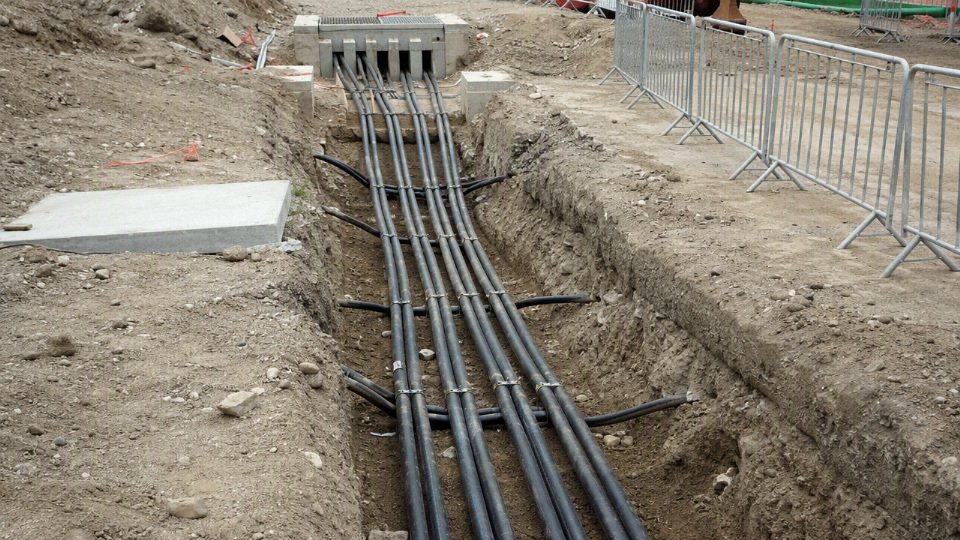
Pulling, bending, and drum handling
Pulling damage is often invisible on the day of installation. The sheath may look acceptable, while the insulation screen has been stressed at a bend or the conductor has been stretched beyond what the accessory kit can tolerate later.
The installation plan should define:
- Maximum pulling tension
Confirm the allowable value from the cable manufacturer or project specification. The limit depends on conductor material, conductor size, pulling method, armor, and whether the force is applied through the conductor or a pulling eye. Sidewall pressure at bends
A long straight pull may be acceptable, then become abusive at one tight duct bend. Sidewall pressure rises with tension and bend curvature, so large-radius bends, intermediate pulling points, and correct pulling direction matter.Minimum bending radius
Respect both permanent and during-installation bending radius limits. Armored, screened, or single-core MV cables usually need more generous handling than low voltage building wire. The manual wins over habit here.Pulling direction
Pull from the end that gives fewer severe bends under high tension. On a route with a steep riser or several duct bends, reversing direction can be the difference between a clean pull and a damaged cable.Rollers and guides
Use enough rollers that the cable does not scrape concrete, tray edges, or rebar. Corner rollers should match the cable diameter and bend requirement, not whatever is lying in the electrical store.Lubricants
Use cable-compatible pulling lubricant, especially in ducts. Grease, oil, or improvised soap mixtures can attack sheath materials or leave residue that makes later work messy.Winch control
A winch with tension monitoring is strongly preferred on MV work. Jerky pulling, radio delays, and “give it a bit more” operation from the far end are how expensive drums get ruined.Drum handling
Roll drums only in the marked direction, lift with proper shafts or spreader arrangements, and store them on stable ground. Letting a drum sink into soft soil or sit in standing water is a poor start for a critical feeder.
The field rule is simple: if the route requires force, tight bends, or improvisation, the route is not ready for the cable. Fix the obstruction, open the pit, increase the bend radius, or split the pull.
Laying conditions and site cleanliness
Cable laying should be stopped or controlled when the site conditions can damage the sheath or make the cable too stiff to handle safely. Low ambient temperature is a common issue. Many polymeric sheaths become less forgiving in freezing conditions, and a cable dragged around a cold yard can crack or scuff more easily than the same cable handled on a mild day. The exact minimum installation temperature must be checked against the cable datasheet or supplier instruction.
Pay close attention to these site risks:
- Sharp edges: tray burrs, duct mouths, steelwork, concrete corners, and temporary scaffolding clamps.
- Dirty ducts: stones, welding rods, broken draw wires, mud, hardened grout, or collapsed sections.
- Water accumulation: flooded ducts and pits can hide debris, increase pulling resistance, and expose damaged sheaths to long-term moisture.
- Poor bedding: rocks or construction waste under buried cable can create point pressure after backfilling.
- Uncontrolled traffic: forklifts, skid steers, or trench compactors crossing unprotected cable before final cover.
- Incorrect cleating: especially on single-core cables where short-circuit forces can be high.
There is a trade-off between rugged mechanical protection and heat dissipation. Heavy duct banks, armored construction, concrete encasement, and closed trays protect the cable physically, but they can reduce heat release and lower current-carrying capacity. The preferred choice flips when the main risk changes: a refinery pipe rack may justify open, inspected tray with fire protection and spacing, while a public road crossing usually needs buried duct or reinforced protection even if ampacity must be derated.
Screen bonding, earthing, and link boxes
Screen bonding is not just an earthing detail to be copied from an old drawing. It controls touch voltage, fault current return paths, induced sheath voltage, and losses from circulating current.
Common arrangements include:
| Bonding arrangement | Where it is used | Main benefit | Main caution |
|---|---|---|---|
| Both-end bonding | Shorter circuits, substations, industrial feeders | Simple earthing and low screen voltage | Can create circulating current in metallic screens, especially with single-core cables |
| Single-point bonding | Short to moderate runs where sheath voltage can be controlled | Reduces circulating current losses | The unearthed end can develop induced voltage and needs proper insulation and warning |
| Cross bonding | Longer high-load routes divided into sections | Balances induced voltages and reduces screen losses | Requires correct section lengths, transposition discipline, and tested link boxes |
Link boxes must be accessible, labeled, sealed against water, and included in inspection routines. Surge voltage limiters, bonding leads, and earthing bars should match the system design. Incorrect screen earthing can turn a good cable into a warm, inefficient feeder, or worse, leave dangerous sheath voltages during fault or load conditions.
The boundary here is design-specific: there is no universally correct bonding method for every MV cable. Cable length, load current, fault level, installation spacing, screen construction, local earthing rules, and permitted sheath voltage all have to be checked.
Terminations and joints are the high-risk work
Terminations and joints deserve a higher level of control than general cable pulling. A trained jointer, correct kit, clean work area, and patience are not optional extras. Most plants I have worked with eventually learn this the expensive way.
Critical jointing controls include:
- Accessory compatibility: voltage class, insulation diameter, conductor size, screen type, armor, sheath, indoor or outdoor service, and fault rating.
- Correct stress control: geometric stress cones, cold-shrink or heat-shrink stress control tubes, or premoulded bodies must be installed exactly as instructed.
- Cleanliness: no grit, moisture, carbon tracking residue, conductor strand dust, or greasy fingerprints on prepared insulation surfaces.
- Screen cutback accuracy: poor cutbacks create electrical stress concentration at the insulation screen edge.
- Torque control: lugs, shear bolts, glands, and earth connections should be tightened to the specified value or installation method.
- Moisture sealing: especially at outdoor terminations, direct-buried joints, and substation cable basements.
- Phase identification: mark before cutting, confirm before terminating, and verify during commissioning.
The mechanism is straightforward: MV insulation relies on controlled electric fields. A small knife score, dirty stress control interface, trapped void, or misplaced screen edge can create local partial discharge. That discharge carbonizes material over time, heat rises locally, and the failure may appear months later as a “bad cable” even though the factory length was sound.
Commissioning tests after installation
Commissioning should prove that the installed circuit is safe to energize, not punish the insulation. The exact test program depends on the project standard, cable age, accessory type, system voltage, and owner practice.
Typical checks may include:
- Visual and mechanical inspection
Confirm routing, bending, cleats, labels, glands, sealing, terminations, joint positions, and link box condition. Continuity and phasing checks
Verify conductor continuity, phase sequence, screen continuity, and correct connection before energizing.Insulation resistance testing
Useful as a basic gross-defect check, but it does not prove absence of partial discharge defects.Sheath integrity testing
Helps identify outer sheath damage that could permit water ingress or screen corrosion.Very low frequency withstand testing
Common for MV cable commissioning in many markets, subject to the applicable standard and accessory suitability.Damped AC testing
Used in some diagnostic programs to stress the cable in a way closer to AC service than DC methods.Partial discharge diagnostics
Valuable for detecting defects at joints, terminations, or insulation interfaces, but interpretation needs competent equipment and experienced analysis.Bonding and sheath voltage checks
Confirm that bonding links, surge limiters, and earthing conductors match the design.
Old-style DC high-potential testing on aged extruded MV cable is controversial and often restricted by owner standards because it may not represent service stress and can leave space charge effects. Do not select a test just because a contractor owns the equipment; select it because the cable type, accessory system, and governing standard support it.
Operating practices after energization
Once energized, the cable becomes part of the plant’s production risk profile. It should be inspected and loaded like a critical asset, not forgotten until a feeder trips.
Good operating practice includes:
- Thermal monitoring: use SCADA load trends, substation meters, infrared inspection at terminations, or distributed temperature sensing where justified by circuit value.
- Load management: watch seasonal peaks, motor starting duty, harmonic heating, emergency backfeeds, and temporary operating modes after shutdown work.
- Periodic route inspection: check trenches, exposed tray, risers, tunnels, cable basements, cleats, glands, and link boxes.
- Sheath voltage checks: especially on single-point bonded and cross-bonded systems.
- Discharge warning signs: ozone smell, tracking marks, audible noise, powdery residue, unusual heating, or repeated protection alarms.
- Water control: keep pits, basements, and link boxes drained and sealed. A perfect drawing does not help if the link box spends monsoon season underwater.
Common field failure causes remain depressingly consistent: overbending, excessive pulling force, contaminated jointing surfaces, water ingress, incorrect screen earthing, damaged sheath, incompatible accessory kits, and thermal overload. The commercial consequence is usually larger than the cable replacement cost. A failed MV feeder can stop a production line, damage switchgear, force temporary generation, and burn through the savings from choosing the cheapest installer.
Procurement and supplier evaluation
A medium voltage cable quotation is only useful when the buyer has locked down both the electrical design basis and the delivery conditions. The cheapest per-meter offer can become the most expensive option if it arrives with the wrong screen capacity, undocumented material substitution, drum lengths that force extra joints, or test records that do not match the project standard.
Before asking for price, give suppliers a controlled technical request rather than a sketchy cable name. At minimum, the inquiry package should state:
- Voltage rating and system voltage: for example, IEC-style Uo/U and Um values, or the applicable North American voltage class.
- Governing standard and edition: IEC, ICEA, AEIC, BS, AS/NZS, utility specification, or project-specific supplement.
- Conductor material and size: copper or aluminum, circular compacted or sector-shaped where relevant, and required cross-sectional area or AWG/kcmil size.
- Core count and cable arrangement: single-core, three-core, triplexed, or parallel runs.
- Insulation system: commonly XLPE or EPR, including any tree-retardant or special insulation requirement if specified.
- Metallic screen or shield: copper tape, copper wire, aluminum laminate, lead sheath, or other design; include required earth-fault current and duration if known.
- Armor requirement: steel wire, steel tape, aluminum wire, corrugated metal sheath, or no armor, based on mechanical exposure and single-core magnetic loss constraints.
- Outer sheath material: PVC, PE, LSZH, oil-resistant, UV-resistant, termite-resistant, or other compound.
- Fire performance: flame retardant, low smoke zero halogen, circuit integrity, or local building/fire authority requirements.
- Installation method: direct buried, duct bank, tray, tunnel, submarine landing, vertical shaft, or open-air industrial routing.
- Route length and pulling sections: include spare length, joint bay locations, and expected pulling direction if known.
- Drum constraints: maximum drum diameter, width, weight, forklift/crane limits, container loading limits, and site access restrictions.
- Accessories: terminations, joints, lugs, glands, link boxes, bonding leads, surge arresters, and compatibility requirements.
Price comparison should start after technical equalization, not before. A lower number may reflect a legitimate manufacturing efficiency, but it can also hide thinner sheath tolerances, a different conductor class, weaker documentation, or a screen design that meets normal shielding needs but not the project’s earth-fault duty. Conductor resistance is a good example: a cable that barely meets the resistance limit may still comply, but over a heavily loaded feeder its I²R losses turn into extra heat, voltage drop, and lifetime operating cost. That is not academic on a plant feeder running near capacity every summer.
| Quotation item | What to compare | Why it matters commercially |
|---|---|---|
| Design compliance | Rated voltage, insulation thickness, screen design, sheath, armor, fire performance | Prevents later rejection by the consultant, utility, or site inspector |
| Conductor details | Material, class, resistance, compaction, tolerances | Affects losses, ampacity margin, termination fit, and copper/aluminum value |
| Material grade | Insulation compound, sheath compound, water-blocking materials, armor material | Determines service behavior, not just catalog appearance |
| Testing scope | Routine tests, sample tests, type test evidence, partial discharge records where applicable | Separates verified production from paper compliance |
| Documentation | Datasheets, drawings, test reports, certificates, packing lists, traceability records | Controls approval speed and claim handling |
| Packing and drums | Drum construction, lagging, sealing, length tolerance, marking | Reduces transit damage and site confusion |
| Delivery terms | Incoterms, production lead time, inspection timing, shipping route | Changes landed cost and schedule risk |
| Warranty and support | Defect response, technical clarification, replacement process | Matters most when installation crews are already mobilized |
Do not compare medium voltage cable only by unit price unless every construction detail, test obligation, drum length, and delivery term has first been made equivalent. In practice, that equalization step is where many bad buys are caught.
Supplier evaluation should look past a glossy brochure. Useful capability indicators include production history in medium voltage cable, dedicated MV extrusion lines, quality management discipline, in-house or coordinated testing capability, engineering support that can answer design questions without guessing, export experience, available capacity during the required production window, and a clear after-sales response process. Ask who will review the technical deviations, who signs the inspection and test plan, and who responds if the site finds a damaged drum or a missing test certificate.
For an international project, logistics can be just as decisive as insulation design. Long drum lengths reduce the number of joints, which usually improves reliability and shortens installation work, but oversized drums can create another problem: blocked container loading, overweight inland transport, crane limitations, or cable that cannot turn into the switchgear room. The preferred point flips when the cost and risk of handling a large drum exceed the benefit of eliminating one joint. That boundary depends on site access, pulling equipment, route geometry, and the skill level of the installation contractor.
Project execution checks should include:
- Confirm drum size and gross weight against port, warehouse, road, and site lifting limits.
- Define cable length tolerance per drum and how surplus or shortage will be handled.
- Require durable shipping protection, end caps, moisture sealing, and export-grade lagging where needed.
- Specify marking on the sheath and drum flanges, including cable type, voltage, length, drum number, and project reference.
- Agree storage requirements, especially for outdoor yards with UV exposure, standing water, or poor ground conditions.
- Set the documentation language and format before production, not after the shipment is ready.
- Schedule inspection hold points with realistic notice periods.
- Maintain batch traceability from raw material and production lot through drum number and test record.
Risk signs deserve a hard stop or at least a formal clarification. Watch for vague voltage notation, no standard edition, missing conductor resistance data, unclear metallic screen fault-current capacity, no partial discharge evidence where the applicable standard requires it, substitute sheath or insulation materials, altered armor design, incomplete routine test reports, or certificates that do not identify the actual cable lot. A supplier that will not state deviations in writing is asking the buyer to accept hidden risk.
An integrated manufacturer such as Jinda can support international cable projects through coordinated R&D, production, sales, technical support, and after-sales service across a large manufacturing base. For bulk procurement, that matters because technical clarification, production planning, inspection coordination, export packing, and long-term supply scheduling have to move together rather than as disconnected handoffs.
Before releasing bulk production, align four items in writing: approved technical datasheet and drawings, commercial terms and warranty conditions, production and inspection schedule, and final shipping plan. Once the extrusion run starts, changes become expensive; once the drums ship, mistakes become site delays.
Frequently asked questions
What voltage range is considered medium voltage?
Medium voltage is not defined identically in every market, but power cable buyers usually treat it as the range above low voltage and below transmission-level high voltage. Common project classes include IEC ratings from 3.6/6 kV up to 26/35 kV, and North American classes such as 5 kV, 15 kV, 25 kV, and 35 kV. Always match the tender, utility rule, or governing standard instead of relying on a casual voltage label.
Is 1 kV cable a medium voltage cable?
No, 1 kV cable is normally treated as low voltage cable. It may still be heavily built, armored, flame-retardant, or used in industrial plants, but that does not make it medium voltage. Medium voltage cable needs a controlled insulation system with conductor screen, insulation screen, metallic screen, and tested discharge performance; a typical 0.6/1 kV power cable is not designed that way.
What is the difference between medium voltage and high voltage cable?
The practical difference is not only rated voltage; it is insulation design, electric field control, accessories, testing, installation skill, and failure consequence. High voltage cables operate under higher electrical stress and usually require more demanding insulation thickness control, screen design, jointing practices, sheath bonding studies, and commissioning tests. The boundary depends on the standard or utility classification being used, so do not mix IEC, IEEE, and local grid terminology without checking the actual voltage rating.
Why do medium voltage cables need conductor and insulation screens?
Screens smooth the electric field so the insulation is not exposed to sharp stress points. The conductor screen fills microscopic gaps between stranded conductor and insulation, while the insulation screen creates a controlled outer electrical boundary around the insulation. Without these layers, small voids, protrusions, or contamination can concentrate stress and start partial discharge; once that begins, insulation damage tends to grow rather than heal.
Which is better for medium voltage cable, XLPE or EPR?
XLPE is usually preferred where low dielectric loss, good thermal rating, broad standards acceptance, and cost-effective production are the priorities. EPR is often chosen where flexibility, moisture tolerance, or repeated movement matters more, such as mining, trailing, shipboard, or certain harsh industrial duties. In practice, the better choice depends on installation method, bending demand, water exposure, fire requirement, accessory compatibility, and the buyer’s standard.
Should I choose copper or aluminum conductor?
Copper gives lower resistance in a smaller cross-section and is easier to terminate in many crowded switchgear and transformer boxes. Aluminum is lighter and often cheaper per ampere, but usually needs a larger conductor size and more attention to lugs, oxide control, joint compound, and tightening practice. For long feeders, total installed cost should include cable price, pulling load, tray fill, termination hardware, losses, and the plant’s maintenance discipline.
When does a medium voltage cable need armor?
Armor is justified when the cable faces mechanical damage, direct burial risk, rodent attack, poor backfill, exposed industrial routes, or installation in areas where people may strike it with tools or mobile equipment. It is not automatically needed in a clean duct bank or well-protected cable trench. Armor adds weight, diameter, bending stiffness, and termination work, so specifying it “just to be safe” can create handling problems and higher installed cost.
Can single-core medium voltage cables use steel wire armor?
Usually no, not for AC circuits, unless the design has been specifically engineered and verified for that duty. Steel armor around a single-core AC cable can suffer induced magnetic losses and heating because the magnetic field is not naturally balanced inside one cable. Non-magnetic armor materials are commonly used for single-core AC medium voltage cables; for three-core cables, steel wire armor is much more common because the phase fields largely cancel.
What causes partial discharge in medium voltage cables?
Partial discharge usually starts where the electric field is high enough to break down a small gas-filled void or weak interface inside the insulation system. Common causes include:
- Voids, contamination, or protrusions from manufacturing defects.
- Poorly stripped semi-conductive screen at a termination.
- Moisture ingress through damaged sheath or bad sealing.
- Incorrect accessory installation, especially stress cone errors.
- Sharp bending, crushing, or impact damage during pulling.
- Incompatible joints, lugs, or heat-shrink and cold-shrink kits.
A good factory test package reduces manufacturing risk, but accessory workmanship in the field is just as critical.
How long should a medium voltage cable last?
A correctly specified, manufactured, installed, and operated medium voltage cable is often expected to serve for decades. The actual life is controlled by conductor temperature, cyclic loading, water exposure, sheath damage, partial discharge, short-circuit events, accessory quality, and how often the route is disturbed. A cable running near its thermal limit in wet, chemically aggressive soil will not age like the same cable in a dry indoor tray with stable loading.
What tests should be requested before shipment?
At minimum, request evidence aligned with the purchasing standard and project specification, not just a sales datasheet. Typical shipment-related checks include:
- Routine test records for the production length.
- Conductor resistance test.
- Voltage withstand test.
- Partial discharge test where required by the standard.
- Dimensional checks for insulation, screens, sheath, and armor.
- Spark or sheath integrity checks where applicable.
- Drum number, length, marking, and packing confirmation.
- Type test reports for the cable family, when required by the buyer or utility.
For critical projects, agree on inspection hold points before production starts. Trying to add them after the cable is already on drums rarely works cleanly.
What information is needed for an accurate quotation?
A usable quotation needs more than voltage and conductor size. Provide:
- Rated voltage and applicable standard.
- Conductor material, size, and core count.
- Copper wire screen or tape screen requirements.
- Insulation material, usually XLPE or EPR.
- Armor type, if needed.
- Outer sheath material and color.
- Flame, smoke, sunlight, oil, termite, or chemical resistance requirements.
- Installation method: tray, duct, direct burial, tunnel, mine, marine, or overhead support.
- Ambient temperature, soil thermal condition, and expected load current if ampacity is part of the scope.
- Required test documents, inspection level, and certification package.
- Drum length limits, destination, packing rules, and delivery schedule.
Clear project data prevents the common procurement problem: receiving several “compliant” prices that are not technically the same cable.
Verify your cable specification
Use this final check before issuing a purchase order, not after the cable drums are already in production. A medium voltage cable is not just a voltage-rated product; it is an engineered system matched to electrical stress, thermal duty, fault behavior, installation environment, accessories, standards, and evidence requirements. If one of those pieces is assumed incorrectly, the problem usually appears later as derating, termination failure, sheath overheating, site delay, or a dispute over compliance documents.
Final specification checklist
Confirm these items in the enquiry, technical schedule, and supplier quotation:
- Voltage class
- IEC designation such as 3.6/6 kV, 6/10 kV, 8.7/15 kV, 12/20 kV, 18/30 kV, or 26/35 kV.
- North American class such as 5 kV, 15 kV, 25 kV, or 35 kV where applicable.
- System earthing arrangement and maximum operating voltage, not just the nominal network voltage.
- Governing standard
- IEC, ICEA, AEIC, BS, AS/NZS, project utility specification, or local authority requirement.
- Required type test certificates, routine test records, inspection hold points, and language or legalization needs for export documents.
- Conductor
- Copper or aluminum.
- Cross-sectional area or AWG/kcmil size.
- Stranded, compacted, water-blocked, or sector-shaped construction if specified.
- Required continuous current rating and allowable voltage drop.
- Insulation and screens
- XLPE or other specified insulation system.
- Conductor screen, insulation screen, and metallic screen design.
- Copper tape, copper wire, or other screen arrangement.
- Screen bonding method: single-point, both-end, cross-bonded, or project-specific earthing.
- Fault and thermal duty
- Conductor short-circuit withstand.
- Metallic screen earth-fault current and duration.
- Emergency loading assumptions, if any.
- Installation grouping and cyclic load profile.
- Mechanical and environmental protection
- Armored or unarmored design.
- Steel wire, aluminum wire, steel tape, or other armor where applicable.
- Sheath material such as PVC, PE, LSZH, or oil-resistant / UV-resistant compounds where specified.
- Moisture barrier, water-blocking, termite protection, chemical exposure, or abrasion requirements.
- Fire behavior
- Flame retardant, low-smoke halogen-free, fire-resistant, or circuit integrity requirements.
- Tunnel, plant room, offshore, mining, data center, or public infrastructure rules if they apply.
- Installation method
- Direct buried, duct, tray, tunnel, riser, aerial, submarine, or mining installation.
- Minimum bending radius, pulling tension, sidewall pressure, and expected pulling route.
- Drum length, drum weight, flange diameter, and access limits at site. A beautiful cable schedule is not useful if the drum cannot pass the gate or fit the payoff stand.
- Accessories
- Terminations, joints, separable connectors, glands, lugs, screen bonding kits, link boxes, and surge arresters.
- Compatibility between cable construction and accessory supplier instructions.
- Packing and delivery
- Required drum markings, packing protection, certificates, test reports, inspection release notes, and shipping terms.
- Delivery schedule by drum lot, not only total project quantity.
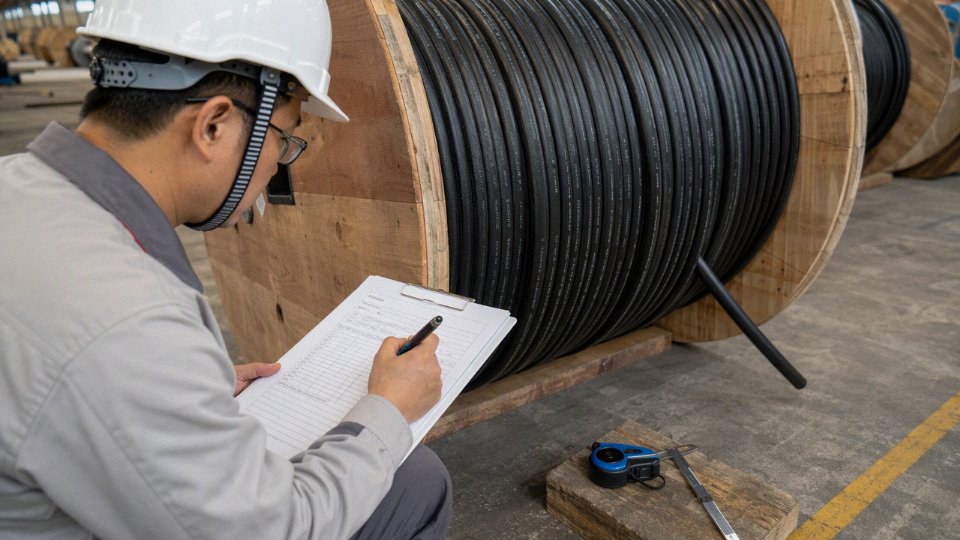
The assumptions most worth challenging before procurement are soil thermal resistivity, screen earthing design, earth-fault duration, drum length limits, and accessory compatibility. These are the items that often sit outside the cable datasheet but control whether the selected cable actually works in the installed system. For buried routes, seasonal soil moisture can change ampacity enough to matter; for long feeders, screen bonding can turn a sound electrical design into an avoidable heating problem.
Involve the manufacturer early when the route or duty is outside routine distribution work. That includes high fault current, long renewable energy collector circuits, mining cables, submarine or wet-route service, special fire-performance demands, export documentation packages, and bulk multi-drum supply where production sequencing and drum matching affect site progress.
Jinda has operated since 1987 and supports international cable projects through integrated R&D, production, sales, technical support, and after-sales service.True
This is based on the supplied company profile for Shandong Jinda Special Cable Group Co., Ltd.; project-specific capability still depends on the requested cable standard, construction, testing scope, and delivery requirement.
For the next step, send the project voltage rating, governing standard, conductor material and size, route length, installation method, required current rating if known, accessory requirements, and delivery schedule. Jinda can review the specification, align it with applicable standards, plan production against the required cable construction and drum quantities, and provide an engineering-backed medium voltage cable recommendation and quotation for international supply.