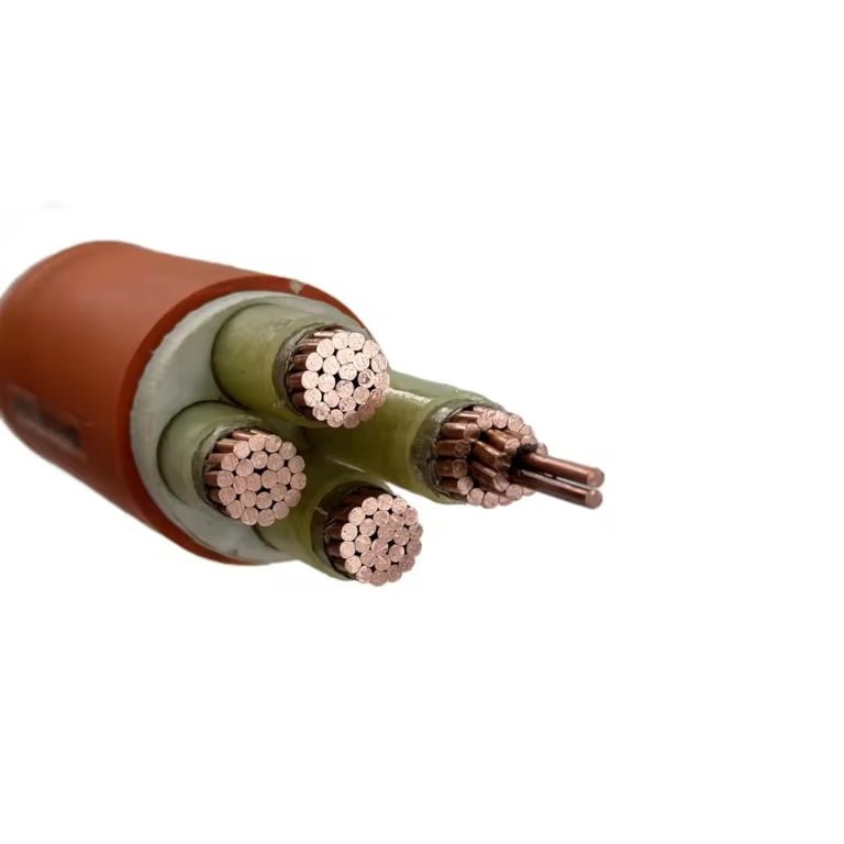
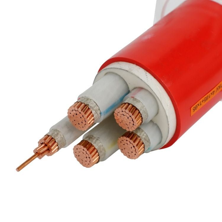
A medium voltage cable without a properly designed fault-return and bonding path is not just a code argument; it becomes a plant reliability problem. Ground faults may clear slowly, shields can overheat, terminations can track, and exposed metal can sit at dangerous touch voltage. The cost shows up as nuisance trips, failed cable ends, outage hours, and emergency replacement work — so the right question is not “ground wire or no ground wire,” but “what grounding system does this cable installation actually require?”
A medium voltage cable does not always require a separate ground wire, but it does require a verified grounding path. Depending on the standard and installation, that path may be a copper tape shield, copper wire shield, concentric neutral, lead sheath, armor, or a separate equipment grounding conductor sized for fault current and clearing time.
That distinction is where many specifications get messy. A 15 kV feeder in tray, a 35 kV utility-style circuit, and an armored industrial cable pulled through a wet area can all look similar on a one-line diagram, yet need different grounding and bonding decisions once fault current, shield continuity, terminations, and touch voltage are checked.
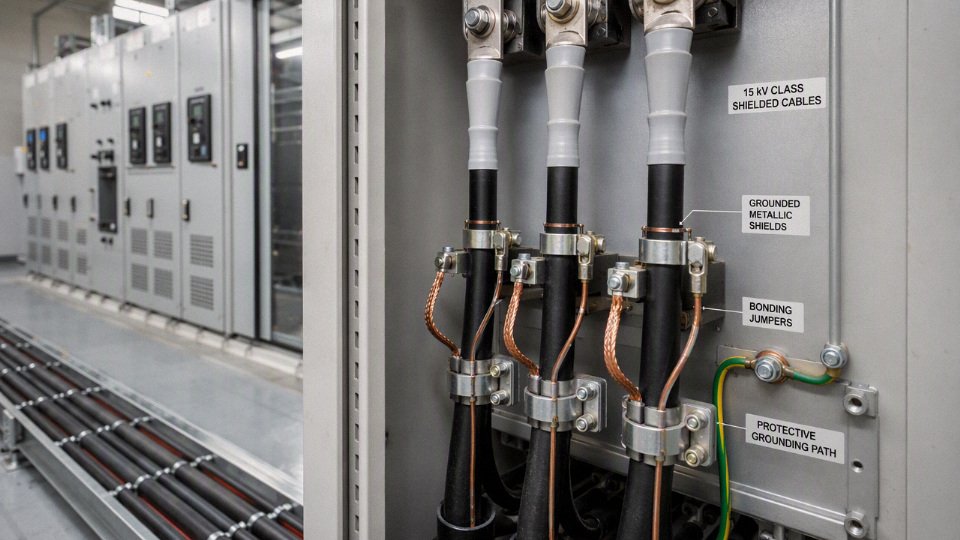
Cable grounding anatomy
A medium voltage cable does not have one universal “ground wire”; it has several layers and metallic components that may perform shielding, bonding, neutral, mechanical protection, or fault-current duties. The right specification starts by naming the part: shield, concentric neutral, armor, sheath, or separate equipment grounding conductor, because each behaves differently during charging current, induced voltage, and fault conditions.
The cable layers and what each one is allowed to do
In a typical medium voltage cable, the current-carrying path is only one part of the design. Around it are stress-control, insulation, metallic, and protective layers. Mixing up these functions is how procurement drawings end up saying “ground wire” when the installation actually needs a copper wire shield, a concentric neutral, or a separate equipment grounding conductor.
The main parts are:
- Phase conductor
This is the copper or aluminum conductor that carries load current. Its size is selected for ampacity, voltage drop, short-circuit withstand, installation conditions, and termination compatibility. It is not a grounding element unless a fault has already occurred, and even then the fault path should be through designed metallic return paths, not through damaged insulation or random plant steel. - Conductor screen
A semi-conductive layer over the conductor smooths out the electric field where conductor strands would otherwise create local stress peaks. It is not metallic grounding. Its job is field control at the conductor surface, which matters because medium voltage insulation failures often start at stress concentrations, contamination, voids, or poor termination workmanship. Insulation
XLPE, EPR, or similar insulation holds back the system voltage. Its thickness and material depend on the voltage class, insulation level, standards, and service environment. Insulation does not “float” electrically on its own; it works with the conductor screen and insulation screen to keep the electric field controlled.Insulation screen
This semi-conductive layer over the insulation gives the metallic shield a smooth electrical interface. In terminations, this layer must be cut back and finished correctly. A nick, step, or dirty edge here is not a cosmetic issue; it can turn into partial discharge, tracking, or early termination failure.Metallic shield or screen
This is the first layer many people casually call “ground.” It may be copper tape, copper wires, a wire-and-tape combination, a concentric neutral, a lead sheath, a corrugated metallic sheath, or another metallic screen depending on the cable design. Its duties are electrical, not just symbolic.Bedding or inner covering
Bedding separates and cushions metallic layers, especially under armor. It helps prevent mechanical damage during manufacture, bending, pulling, and operation. It is not used as a grounding path.Armor
Steel wire armor, steel tape armor, aluminum wire armor, or other armor systems provide mechanical protection. Armor may be bonded and may contribute to grounding in some designs, but that must be verified. With single-core AC cables, ferromagnetic armor around each phase can create heating problems, so armor choice is not just a mechanical decision.Outer sheath or jacket
PVC, PE, LSZH, or other jacket materials protect against moisture, abrasion, sunlight, oil, chemicals, termites, and general site abuse. The jacket is not a grounding element; it protects grounding and shielding components from becoming corroded, discontinuous, or unsafe. I have seen good shield designs defeated by a jacket sliced during pulling and left unsealed in a wet cable trench.Optional separate equipment grounding conductor
This may be included inside a three-core cable, run alongside single-core cables, pulled in the same conduit, or installed separately in tray according to the design rules and applicable code. It is usually bare or insulated copper, though project standards vary.
What the metallic shield actually does
The metallic shield has several jobs at the same time, which is why underspecifying it causes trouble later. It helps equalize electric stress around the insulation screen, provides a return path for the cable’s capacitive charging current, reduces electric field outside the cable, and gives the termination kit a defined grounded reference. Under defined conditions, it may also carry ground-fault current long enough for protective relays or fuses to clear.
The mechanism is simple but unforgiving. In service, the energized conductor and grounded shield form a cylindrical capacitor. Charging current flows continuously through the shield bonding system, usually small compared with load current but important for voltage stability and sheath voltage calculations. During a phase-to-shield fault, the shield or connected ground path may see a much higher current for a short time. Its survival depends on metallic cross-section, material resistivity, bonding quality, fault level, clearing time, thermal limits, and how evenly the current divides among parallel paths.
A shield that is acceptable for electric field control is not automatically acceptable for high ground-fault duty. That is the trap.
Any medium voltage cable shield can replace a dedicated equipment grounding conductor.False
A metallic shield can perform grounding-related duties only within its verified current-carrying capacity, bonding arrangement, and applicable standard. Thin tape shields may control the electric field but may not have enough fault-current withstand for a specific industrial protection scheme.
Metallic shield, sheath, neutral, and armor options
The electrical continuity and fault-current capacity of metallic layers vary widely. Manufacturer data and project calculations matter here; a drawing symbol alone does not tell you the short-time withstand.
| Metallic component | Usual strength | Common limitation | Where it is often seen |
|---|---|---|---|
| Copper tape shield | Good electrostatic shielding and stress control; compact construction | Limited fault-current capacity if tape cross-section is small; overlap and termination quality matter | Industrial MV feeders, switchgear-to-transformer runs |
| Copper wire shield | Better longitudinal continuity and easier bonding than tape in many terminations | Fault capacity depends on number and size of wires; wires can be damaged during stripping | Industrial and utility distribution cables |
| Copper wire plus tape shield | Combines circumferential shielding with improved longitudinal current path | Higher cost and diameter; must be terminated correctly | Higher-spec industrial feeders, critical circuits |
| Concentric neutral | Can serve as neutral and grounding return in some utility designs | Neutral duty and grounding duty must be intentionally designed; corrosion or broken strands reduce safety margin | Utility distribution, pad-mounted transformer systems |
| Corrugated metallic sheath | Strong moisture barrier and continuous metallic path | Terminations and bonding hardware are more specialized; bending limits matter | Substations, tunnels, wet or demanding routes |
| Lead sheath | Excellent moisture barrier and stable shielding in harsh environments | Heavy, costly, lower mechanical toughness unless protected; environmental handling concerns | Legacy systems, petrochemical, special wet-service designs |
| Metallic armor | Mechanical protection; may be bonded as part of grounding system | Not always a reliable fault path by itself; magnetic heating risk on single-core AC cables with steel armor | Direct burial, tray, industrial plants, mining-style installations |
The trade-off is usually between electrical robustness, installability, and cost. Copper tape is compact and economical, but it may not satisfy a high ground-fault duty unless supported by a separate ground path. Copper wire shields and concentric neutrals give better longitudinal current paths, but they increase diameter and termination labor. Metallic sheaths improve moisture protection and continuity, but they bring bending, gland, bonding, and procurement constraints. The preferred design flips when the installation changes from a short indoor switchgear run to a long wet trench, a cable tunnel with induced sheath voltage concerns, or a utility loop where neutral current is part of the normal operating model.
Where a separate grounding conductor fits
A separate equipment grounding conductor is used when the shield, sheath, armor, or neutral is not intended or not sufficient to serve as the protective grounding path. In industrial plants, I generally prefer seeing this explicitly shown on the cable schedule and one-line diagram rather than hidden inside vague notes. It saves arguments during installation and later during relay coordination checks.
Common arrangements include:
- Inside a three-core medium voltage cable
The cable may include one or more grounding conductors under the overall jacket. This keeps the phase conductors and ground path together, helps routing discipline, and reduces the chance that the ground conductor is omitted in the field. Laid alongside single-core cables
A bare or insulated ground conductor may be installed in the same tray, duct bank, or trench with the phase cables. Spacing, bonding, and grouping matter, especially where induced voltages and circulating currents are being reviewed.Pulled in conduit with the phase conductors
This is common in plant distribution where conduit is already part of the wiring method. The designer still has to confirm conduit fill, pulling tension, thermal derating, and whether the metallic conduit itself is being counted as part of the grounding path.Provided separately in cable tray or grounding grid connections
This can work well in substations and heavy industrial areas, but the route must be controlled. A ground conductor that wanders away from the phase cables can increase loop impedance and produce less predictable fault-current behavior.
Neutral is not the same word as ground
A concentric neutral may carry load imbalance current, return current, and grounding-related fault current in some utility distribution designs. That does not mean every industrial medium voltage cable with metallic wires has a usable neutral. The system grounding method, transformer connection, protection scheme, and applicable standard decide the function.
Industrial plants often separate the neutral function from the equipment grounding function, especially on three-phase MV feeders feeding transformers, motors, or switchgear lineups. The grounding conductor is then sized and routed to clear faults and bond exposed conductive parts, while the cable shield is bonded for electric field control, charging current, and safe termination behavior. Those duties overlap physically in some cable designs, but they should not be confused commercially or electrically.
The counter-intuitive failure mode is a shield that looks comforting on paper but is electrically weak in the field. A thin tape shield with poor overlap, a wire shield with corroded strands, an armor layer bonded at one end only when the protection study assumed both ends, or a termination where the shield pigtail was cut short to “make it fit” can all leave the system with a grounding feature that does not perform during a real fault. A complete grounding review checks ground-fault current, clearing time, shield or ground conductor withstand, bonding method, touch voltage, induced sheath voltage, and termination continuity before the purchase order locks the construction.
Code requirements by system
There is no universal medium voltage “ground wire” rule that travels cleanly from one country, utility, mine, plant, or renewable project to the next. What is consistent is the engineering duty: metallic shields or screens are normally grounded at terminations, splices, and defined bonding points, and any equipment grounding path must be proven for fault current, clearing time, continuity, touch voltage, and the governing standard.
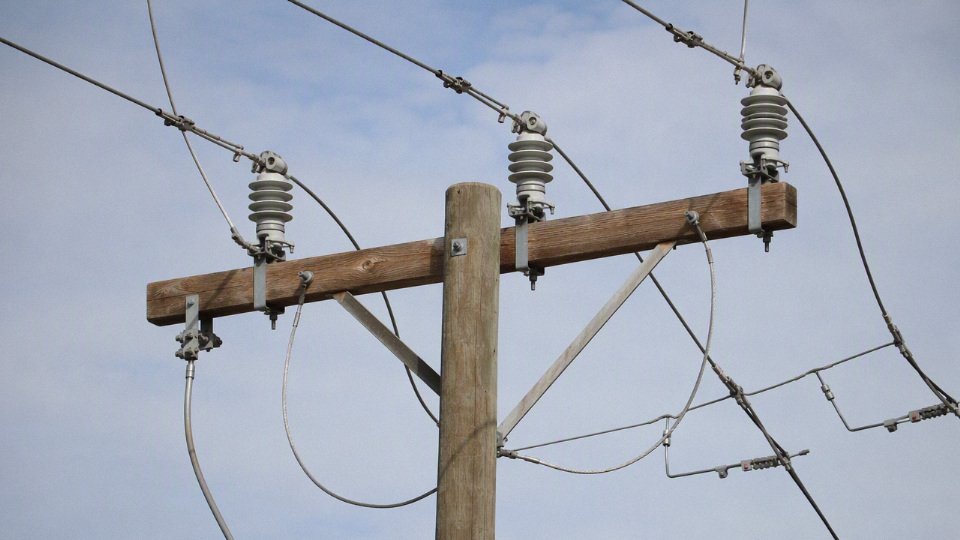
Most code arguments start because people use one word, “ground,” for several different obligations. A code inspector may be asking for an equipment grounding conductor. A utility engineer may be focused on concentric neutral ampacity and arrester grounding. A cable manufacturer may be referring to shield bonding. A protection engineer may be checking whether a ground fault will produce enough current, for long enough, to operate the relay without overheating the shield or putting a dangerous voltage on a tray, gland plate, or termination box.
For medium voltage cable, the safer procurement position is to specify the grounding function required by the applicable system rules, not just ask whether the cable “has a ground wire.” That usually means reviewing the installation standard, the owner’s electrical specification, the utility interconnection document, and the protection study before freezing the cable construction.
Premises wiring and utility distribution are not governed the same way
Inside an industrial plant, commercial facility, hospital, data center, port, mine, rail depot, solar farm, or wind project collector system, MV cable is often treated as part of premises wiring or a private distribution network. The design may be checked against national electrical code requirements, local inspection rules, an owner engineering standard, insurer requirements, and equipment vendor requirements for switchgear, transformers, drives, or generators.
Utility distribution is different. A utility may allow or require cable constructions that are not typical for a factory feeder. Concentric neutral cable, bare neutral wires, multi-grounded neutral systems, jacketed primary cable with tested neutral corrosion allowance, or specific grounding intervals may be part of a utility’s standard practice. The same cable might be rejected by a plant engineer because the plant wants an insulated equipment grounding conductor in the tray, or because the owner does not want neutral current sharing through tray steel and building bonds.
In practice, these project types often land in different rule mixes:
- Industrial plants and process facilities: commonly use national premises wiring rules plus owner standards, arc-flash studies, relay coordination studies, and plant grounding grid criteria. Resistance grounding is common in some plants to reduce damage from the first ground fault.
- Commercial buildings and data centers: tend to be strict about equipment grounding continuity, listed raceway systems, cable tray rules, segregated circuits, and documented inspection paths. The maintenance team needs something they can test without guessing which buried armor bond is still intact.
- Mines and tunneling projects: may have mining-specific grounding, trailing cable, ground-check monitoring, pilot conductor, and rapid trip requirements. Mechanical abuse and wet conductive surfaces make touch voltage more than a paperwork issue.
- Ports, rail, and transit systems: may combine utility-style distribution, stray current control, bonding for rail structures, corrosion control, and owner standards. The bonding decision can affect signaling, cathodic protection, and touch voltage on exposed steelwork.
- Solar farms and wind farms: often combine IEC- or IEEE-style cable specifications, local grid code, inverter or transformer vendor requirements, and collector-system grounding studies. Long feeder runs make induced sheath voltage and single-point bonding decisions more visible than in a short plant feeder.
- Utility feeders: are usually driven by the utility construction standard, protection philosophy, neutral grounding method, arrester practice, and local grid rules rather than a generic building-wiring assumption.
That is why a buyer comparing quotations from different regions can see one supplier offering copper tape shield plus armor, another offering copper wire screen, and a third offering concentric neutral. The cheapest line item may not be acceptable once the project engineer checks the grounding path against the fault study and inspection regime.
Standard families normally considered
Medium voltage cable projects may reference IEC, ICEA, IEEE, NEC, CSA, BS, AS/NZS, and local grid or mining regulations. None of these should be treated as globally dominant. A project in one country may use IEC cable voltage designations such as 8.7/15 kV or 18/30 kV, while still applying local installation law and a utility interconnection standard. A North American industrial project may reference ICEA cable construction, IEEE testing or application guidance, NEC installation requirements, and a site-specific grounding study.
The practical procurement check is not “which standard sounds more international?” It is:
- Which standard governs cable construction? This affects insulation level, shield type, jacket, armor, test requirements, and marking.
- Which rule governs installation? This affects raceway, tray, burial, separation, bonding, ampacity, fire behavior, and inspection.
- Which document governs grounding and protection? This affects ground-fault current, relay settings, clearing time, grounding resistor size, shield withstand, and touch voltage criteria.
- Which authority accepts the work? This could be a local inspector, utility, mine regulator, railway authority, owner’s engineer, insurance reviewer, or commissioning agent.
- Which documents are contractual? A project specification can be stricter than the minimum code, and the purchase order usually decides what the supplier is obligated to deliver.
A medium voltage cable shield or screen is normally grounded at terminations and at specified bonding points, but the exact bonding arrangement depends on the installation standard, system grounding method, and engineered sheath-voltage control.True
This reflects common MV cable practice across standard families, but exact requirements must be verified against the project code, utility specification, and cable system design.
The equipment grounding conductor is a system decision, not just a cable option
Some MV systems require a separate equipment grounding conductor sized for available ground-fault current and protective-device clearing time. That conductor may be copper or aluminum, bare or insulated, inside the cable assembly, installed in the raceway, routed in the tray, or bonded through a grounding grid depending on the rule set. In other systems, the permitted grounding path may be the metallic cable shield, armor, metal conduit, concentric neutral, lead sheath, or a parallel grounding conductor network, provided it meets the required electrical and mechanical criteria.
The mechanism is straightforward but often underestimated. During a ground fault, current returns through whatever metallic path the system gives it. If that path has low impedance and enough thermal capacity, the protective device sees the fault and clears it before the path overheats or exposed metal rises to a dangerous voltage. If the path is discontinuous, corroded, loosely bonded, or too small, the relay may under-see the fault, the shield may be damaged, and touch voltage can appear on equipment frames, tray, armor glands, or termination enclosures.
Metal raceway, cable tray, armor, and shields are not automatically acceptable as the sole equipment grounding path. They must be evaluated for:
- Electrical continuity: bolted joints, expansion fittings, tray splices, gland plates, and paint under lugs all matter. A beautiful tray run can be a poor grounding path if every joint relies on oxidized hardware.
- Impedance: enough current must flow to operate the intended protection within the required time. Long runs, small cross-sections, and ferromagnetic paths can change the result.
- Fault-current withstand: the grounding path must survive the let-through energy until the breaker, fuse, recloser, or relay clears the fault.
- Corrosion and environment: buried armor, wet tunnels, fertilizer plants, salt air at ports, and poorly sealed pull boxes can turn yesterday’s acceptable path into next year’s maintenance problem.
- Mechanical reliability: tray sections get moved, conduits get cut, and glands get replaced during shutdowns. If the grounding scheme depends on workmanship that the maintenance crew cannot inspect, expect trouble.
- Termination continuity: shield wires, tapes, armor, drain wires, and grounding conductors must be bonded through splices, terminations, link boxes, and equipment enclosures as required by the design.
The trade-off is familiar to anyone who has bought cable by the kilometer. Relying on shield, armor, conduit, or a grounding grid can reduce copper content, diameter, pulling weight, and installed cost. A dedicated grounding conductor gives a clearer, more inspectable return path and can reduce arguments during commissioning. The preferred choice flips when the installation is long, exposed, corrosive, frequently modified, or subject to a strict inspector or owner standard. Then the extra conductor often costs less than the field rework.
System grounding method changes the fault duty
The grounding method of the MV system controls ground-fault magnitude, relay behavior, shield heating, and touch-voltage risk. Two cables with the same voltage rating and shield construction can see very different duties on different systems.
| System grounding method | Ground-fault behavior | What it means for cable grounding |
|---|---|---|
| Solidly grounded | Usually high ground-fault current, limited mainly by source and circuit impedance | Grounding path and shield bonds must withstand high short-duration current and support fast protective clearing. Equipment grounding impedance is a major design check. |
| Low-resistance grounded | Fault current is intentionally limited, often still high enough for selective relaying | The grounding path may see lower current than solid grounding, but it still needs thermal withstand and reliable relay operation. Resistor rating and clearing time drive the numbers. |
| High-resistance grounded | First ground fault current is low, often used to keep process loads running while alarming | Bonding and screening are still required. Monitoring, insulation condition, transient overvoltage control, and safe touch voltage remain design issues. |
| Reactance or impedance grounded | Fault current is controlled by grounding impedance and system parameters | Protection sensitivity and transient behavior must be checked. Cable shield duty depends on actual current and clearing time, not the label alone. |
| Isolated or ungrounded | First ground fault current may be capacitive and low, but system voltage to ground can shift | Cable insulation stress, fault location, surge behavior, and personnel voltage exposure require careful engineering. A second fault on another phase can become severe. |
| Resonant grounded | Arc-suppression coil compensates capacitive ground-fault current | Shield bonding and voltage control still matter. Protection and fault detection can be more specialized, so supplier assumptions should be avoided. |
A commonly missed point: high-resistance grounding is not a license to ignore grounding hardware. It reduces damage from the first line-to-ground fault and may allow controlled operation while maintenance locates the fault, which is valuable in process plants. What it sacrifices is simplicity. The plant needs ground-fault monitoring, alarm response discipline, insulation tracking, and a bonding system that keeps exposed metal at safe potential during both normal leakage and abnormal events.
Seasonal moisture is one of those shop-floor details that shows up after commissioning. A feeder that looks stable in a dry FAT or summer megger test may start nuisance alarming in a humid cable basement or after the first monsoon season in outdoor terminations. That does not prove the grounding design is wrong, but it does mean the grounding and monitoring scheme must be maintainable, not just mathematically acceptable.
What the code review should prove before cable purchase
A complete grounding review normally checks ground-fault current, clearing time, metallic shield or ground conductor withstand, bonding method, touch voltage, induced sheath voltage, and termination continuity. Those items should be settled early enough to affect the cable data sheet, not discovered after drums arrive on site.
For a practical review, ask the engineer or supplier to identify:
- Applicable construction and installation standards for the exact country, project type, and authority having jurisdiction.
- System voltage and grounding method, including transformer neutral arrangement, grounding resistor or reactor data, and whether the system is solidly grounded, resistance-grounded, impedance-grounded, isolated, or resonant-grounded.
- Available ground-fault current and clearing time at the cable location, not only at the main switchgear.
- Permitted grounding path, such as separate equipment grounding conductor, shield, armor, metal raceway, concentric neutral, lead sheath, grounding grid, or a combination.
- Shield or grounding conductor thermal withstand, checked against the protective device let-through energy.
- Bonding scheme, such as both-end bonding, single-point bonding, cross-bonding, or link-box arrangement where applicable.
- Touch and transferred voltage limits for accessible equipment, fences, platforms, tray systems, junction boxes, and termination structures.
- Continuity through accessories, including splices, terminations, separable connectors, glands, armor clamps, and bonding jumpers.
- Inspection and maintenance method, because a grounding path that cannot be tested after installation is a poor choice for most owner-operated facilities.
The main conclusion has a boundary: if the project is a short, standard feeder under a well-defined local code and owner standard, the grounding choice may be routine. Once the installation crosses into utility interconnection, mining rules, long renewable collector circuits, corrosive environments, resistance grounding, or special bonding for sheath voltage control, the “does it need a ground wire?” question is too small. The right question is which approved metallic return and bonding system will clear faults, control voltage, survive the environment, and pass inspection for that specific network.
Shield bonding methods
Shield bonding is not a small installation detail; it decides where induced current flows during normal load and where fault current returns during a ground fault. For medium voltage cable, the practical choices are solid bonding, single-point bonding, cross bonding, and multi-point bonding, with the right answer depending heavily on cable length, single-core versus three-core construction, load current, fault level, clearing time, and grounding grid layout.
A cable shield, metallic sheath, armor, concentric neutral, or separate bonding conductor can all be part of the grounding system, but they do not behave the same way electrically. A copper tape shield that is fine for electrostatic screening may not have the same short-circuit capacity as a wire shield or concentric neutral. A steel wire armor may be mechanically useful but can become a heating problem if it sits in the wrong magnetic field. That is why bonding drawings deserve the same review discipline as conductor sizing and relay settings.
Solid bonding at both ends and intermediate points
Solid bonding means the cable metallic shield or sheath is connected to ground at both ends, and often at intermediate manholes, pull boxes, switchgear, transformers, or grounding grid points. It is common because it is simple to install, easy for maintenance crews to understand, and generally gives a strong fault-current return path if the shield or associated ground conductor has adequate withstand.
For short three-phase feeders, especially three-core armored cables or short single-core runs laid in trefoil, solid bonding is often the most practical arrangement. Termination crews can bond the shield at both ends, connect it to the equipment grounding system, test continuity, and move on. There are fewer insulated joints, fewer link box settings, and fewer places for a missing strap or corroded lug to create a hidden defect.
The drawback appears mainly in single-core cable systems. Load current in the phase conductor creates magnetic flux around each cable. That changing magnetic field induces voltage along the metallic sheath or shield. If the shield is bonded at both ends, the induced voltage drives a circulating sheath current around the closed loop. That current produces I²R heating in the shield and nearby metallic parts, reducing the current-carrying capacity of the cable circuit.
The effect is not theoretical. On a long feeder with high continuous current, sheath losses can push cable temperature up even when the copper or aluminum conductor size looks adequate on paper. The problem gets worse when single-core cables are installed with wide phase spacing, in flat formation, or near steel structures that distort the magnetic field. Trefoil formation usually reduces the imbalance because the three phase fields partially cancel, but it does not remove the need to check sheath loss.
Intermediate bonding points make the circuit more robust from a grounding and touch-voltage perspective, but they can also create more closed metallic paths. In a substation trench or industrial cable gallery, that may be acceptable because fault-current sharing and personnel safety are higher priorities than a few percent of loss. On a long export feeder, tunnel route, or high-load plant incomer, the heat penalty can become the deciding factor.
Bonding a medium voltage cable shield at both ends is always electrically safer and always thermally acceptable.False
Both-end bonding usually improves the fault-current return path and reduces standing sheath voltage, but it can create circulating sheath current in single-core cable systems. Thermal acceptability depends on cable formation, route length, load current, shield resistance, bonding layout, and surrounding metallic structures.
Single-point bonding
Single-point bonding grounds the shield or sheath at one location only, typically at one termination, one link box, or one selected grounding point. The open end is insulated from ground, so normal load current cannot circulate through the sheath loop. For long single-core feeders, this can reduce sheath losses and recover ampacity that would otherwise be lost as heat in the metallic screen.
The mechanism is straightforward: the cable still induces voltage along the sheath, but because the metallic path is not closed, there is no continuous circulating current under normal operation. The trade is that the ungrounded end now has a standing induced voltage to earth. That voltage rises with load current, cable length, phase spacing, and installation geometry. During switching surges, lightning impulses, or ground faults, it can rise much higher.
That is where sheath voltage limiters, often metal-oxide type devices, come into the design. They remain non-conductive under normal induced sheath voltage, then conduct during overvoltage events to protect the sheath insulation and termination components. In practice, they need to be accessible, correctly rated, and documented. I have seen otherwise good cable installations made troublesome by link boxes buried under later concrete work or by SVL leads routed like an afterthought with long, inductive loops.
Single-point bonding is useful, but it is not a shortcut. The design normally needs:
- Calculated or tested induced sheath voltage at maximum continuous load.
- Expected temporary overvoltage during ground faults and switching events.
- Sheath insulation rating and jacket integrity.
- SVL rating, energy duty, and failure mode.
- Warning labels or barriers where accessible metallic points may sit above remote earth.
- A maintenance procedure for testing the shield break and limiter condition.
Single-point bonding is attractive when sheath loss is the limiting thermal problem, but it stops being attractive if induced sheath voltage cannot be controlled safely at the open end. That boundary is site-specific; it depends on the feeder length, load current, grounding resistance, and how people can physically contact the installation.
Cross bonding for long single-core routes
Cross bonding is the more engineered answer for long single-core medium voltage cable systems where both sheath loss and induced voltage matter. The route is divided into sections, and the metallic sheaths are connected through link boxes so the induced voltages in the three phases are balanced and largely cancel over a complete major section.
A simplified arrangement looks like this: three single-core cables run from source to load, the route is divided into three minor sections, and the sheath connections are transposed at the link boxes. At the end of a complete cross-bonded section, the summed sheath voltage is low enough that circulating current is greatly reduced compared with straight both-end bonding. The cable circuit remains controlled through grounding points, link boxes, and protective devices rather than leaving long metallic screens floating without protection.
Cross bonding is not something to improvise during installation. It requires accurate phase identification, correct link box wiring, proper sheath sectionalizing or insulating joints, and records that survive the construction phase. A swapped sheath connection may not trip anything immediately, but it can leave one section running hotter than expected or create abnormal sheath voltage at a test point. Commissioning tests should confirm continuity, insulation between sheath sections where required, correct limiter connection, and no accidental bonds through brackets, glands, armor clamps, or water-damaged joints.
The commercial trade-off is plain enough. Cross bonding costs more in design time, jointing skill, link boxes, testing, and route documentation. It pays back where the avoided sheath loss allows a smaller conductor, a higher continuous rating, or lower operating temperature over a long service life. For a 70 m motor feeder inside a plant, cross bonding is usually unnecessary complexity. For a long utility, renewable collector, tunnel, or shore connection route, it may be the only sensible way to combine ampacity and voltage control.
Multi-point bonding in plants, substations, and utility networks
Multi-point bonding connects cable shields, armor, neutrals, ground straps, and equipment grounds into several parts of the grounding network. This is common in substations, industrial plants, utility distribution circuits, and dense electrical rooms where the cable system is part of a larger equipotential bonding system.
The goal is not only to reduce sheath loss. In these installations, designers care about:
- Ground-fault current sharing between cable shields, ground conductors, armor, trays, and grounding grids.
- Touch voltage during faults near switchgear, transformers, motors, and junction boxes.
- Continuity across terminations, splices, and equipment enclosures.
- Reliability when one bond corrodes, loosens, or is removed during maintenance.
- Coordination with protective relays and ground-fault current return assumptions.
- Surge and transient behavior between cable shields and equipment frames.
In a plant network, I tend to favor arrangements that maintenance electricians can inspect and understand without a treasure hunt. A perfect-looking theoretical design is not perfect after ten years if nobody can find the test link, the gland plate was repainted over, and a temporary welding ground has lived on the tray since the last outage. Multi-point bonding is forgiving, but it still needs current-withstand checks. A small copper pigtail with a neat crimp lug is not automatically acceptable for the available ground-fault current and clearing time.
Hardware that belongs in the bonding design
Link boxes, bonding leads, ground straps, shield break joints, insulating joints, sheath voltage limiters, surge protection devices, and test points are not accessories to be priced out at the last minute. They are part of the electrical design, and they should appear on drawings, bills of material, test sheets, and maintenance procedures.
A few details matter more than they look:
| Component | What it does | Common plant-floor issue |
|---|---|---|
| Link box | Provides accessible sheath connections, cross bonding, SVLs, and test links | Wrong phase labeling, water ingress, missing covers, poor access |
| Bonding lead or ground strap | Carries shield, armor, or fault current to the grounding system | Too small, too long, sharp bends, loose lugs, paint under connection |
| Shield break or insulating joint | Separates sheath sections for single-point or cross bonding | Accidental bypass through brackets, glands, tray contact, or moisture |
| Sheath voltage limiter | Limits transient overvoltage across sheath insulation | Incorrect rating, no test record, long inductive leads, failed short or open |
| Test point | Allows continuity, insulation, and limiter checks | Installed but undocumented, unsafe access, no baseline readings |
The mechanical installation affects the electrical result. A bonding lead with a long loop has higher inductance during surge events. A ground strap bolted over paint may pass a continuity beep but fail under high fault current. A stainless enclosure in a wet cable pit may survive corrosion better than painted mild steel, but only if gland sealing and drainage are also right. Small things, but they become outage causes.
Three-core armored cable versus three separate single-core cables
Three-core armored medium voltage cable behaves differently from three separate single-core cables. In a three-core cable, the three phase conductors are close together inside one cable assembly, so their magnetic fields tend to cancel within the armor region. That is one reason three-core armored cable is widely used in industrial distribution, mines, and compact plant feeders. Armor bonding at both ends is usually practical, subject to armor fault-current capacity and local requirements.
With three separate single-core cables, the magnetic field around each cable is not naturally contained in the same way. Installation formation matters. Trefoil formation generally gives better magnetic balance than flat formation. If flat formation is required for pulling, spacing, or heat dissipation, sheath losses and induced voltages need closer checking. Some projects transpose phase positions along the route to balance impedance and induced effects, especially on longer runs.
Ferrous metal around single-core cables is a special warning. Running each phase of a single-core circuit in its own steel conduit or through separate ferrous gland plates can cause serious heating from magnetic losses. If steel conduit is used, all three phases of the same circuit normally need to occupy the same conduit or opening so the net magnetic field is balanced. Non-magnetic gland plates and properly arranged cleats are common choices around single-core terminations for the same reason.
Armor current is another difference. Steel wire armor on single-core AC cables can heat if it forms a magnetic path around one phase. Non-magnetic armor, wire screens, or special constructions may be used depending on the standard and application. For procurement, this is where the phrase “armored MV cable” is not enough. The buyer needs to specify three-core or single-core construction, armor material, screen type, bonding method, installation formation, and expected fault level.
The bonding method that minimizes normal operating losses is not always the method that gives the simplest and strongest ground-fault path. Solid multi-point bonding leans toward fault robustness and easier maintenance; single-point and cross bonding lean toward thermal performance and controlled sheath loss. The correct design sits between those priorities, verified by fault-current withstand, induced voltage, touch-voltage review, and a cable layout that installers can actually build without accidental bonds.
Fault current and touch voltage
A medium voltage grounding path is acceptable only if it can carry the available ground-fault current for the time protection takes to clear, while keeping exposed metal voltage within the project’s safety limits. A shield that is perfectly adequate for electric-field control and charging current may still be inadequate as the fault-return path. That is why the review has to combine cable construction, relay settings, bonding layout, and site grounding impedance, not just a catalog line that says “copper shield.”
The practical engineering inputs are not exotic, but they are often scattered between the utility, the protection engineer, the cable supplier, and the site contractor. Before approving shield-only grounding, armor grounding, or a separate equipment grounding conductor, I would want these items on the same calculation sheet:
- Available ground-fault current at the fault location, not only at the switchgear bus. Long feeders, transformers, grounding resistors, and source impedance can change the value sharply.
- Expected clearing time, including relay delay, breaker opening time, fuse melting and clearing time, or recloser sequence. A “temporary” delay setting left from commissioning can ruin an otherwise reasonable shield sizing calculation.
- System grounding method, such as solidly grounded, resistance grounded, reactance grounded, impedance grounded, resonant grounded, or ungrounded. Each changes both fault magnitude and detection behavior.
- Protective relay and fuse settings, especially ground overcurrent pickup, time dial, definite-time delay, sensitive earth-fault elements, directional elements, and neutral grounding resistor monitoring.
- Cable length and route layout, because impedance, induced sheath voltage, and touch exposure vary between a 60 m motor feeder and a 2.8 km collector circuit.
- Phase conductor size and shield construction, including copper tape thickness and overlap, copper wire count and diameter, concentric neutral area, lead sheath, armor material, or separate grounding conductor size.
- Installation environment, such as steel conduit, cable tray, direct burial, duct bank, tunnel, wet trench, corrosive soil, or shared route with other power circuits.
- Grounding grid impedance and bonding points, including substation grid resistance, plant grid continuity, remote equipment ground rods, link boxes, and structural steel connections.
Short-circuit withstand is an energy problem, not a label
During a ground fault, the metallic shield, armor, concentric neutral, or equipment grounding conductor heats according to the fault current squared multiplied by time, usually expressed as I²t. The mechanism is simple enough: current through resistance produces heat; heat raises conductor temperature; if the metal or adjacent insulation system exceeds its permissible temperature, the shield can anneal, melt locally, lose continuity, damage the jacket, or carbonize semiconductive layers near the insulation shield.
The variables that matter are:
- Conductor material: copper, aluminum, lead, steel armor, or mixed metallic paths do not behave the same. Copper has high conductivity and predictable fault duty; steel armor may have higher impedance, magnetic effects, joint variability, and poorer continuity at accessories unless designed and tested for that duty.
- Metal cross-sectional area: a copper wire shield with many wires can have very different fault capacity from a thin copper tape shield. Tape overlap also matters; a tape shield should not be treated as a solid tube unless the manufacturer’s construction and standard support that assumption.
- Initial temperature: a loaded cable in a hot duct bank starts closer to its thermal limit than an unloaded cable in open air. Summer soil temperature and grouped circuits can make this less forgiving than the desktop case suggests.
- Final permissible temperature: the allowable final temperature depends on the material and the cable/accessory design. It must be verified against the cable standard, supplier data, and termination/splice limits, not guessed from a generic copper table.
- Fault duration: halving current does not simply halve damage; I²t means current has a squared effect, while time is linear. But if lower current makes the relay operate much slower, the heating result can still be worse.
A medium voltage cable shield that can carry normal capacitive charging current is automatically suitable as the ground-fault return path.False
Charging current is normally small and continuous, while ground-fault duty is a short-time thermal and electromechanical event. The shield must be checked for available fault current and clearing time, and a separate equipment grounding conductor may be required by the project standard or calculation.
In practice, this is where procurement descriptions get risky. “Copper tape shield” tells me the insulation shielding method, but it does not tell me whether the shield has enough metallic area for a 6 kA ground fault lasting 0.5 seconds, or a 600 A resistance-grounded fault that may persist until a backup relay trips. The preferred design can flip depending on protection philosophy: a robust wire shield or concentric neutral may be efficient where the cable is expected to carry fault current, while a separate equipment grounding conductor is often cleaner where the shield’s main job is electrostatic control and termination stress management.
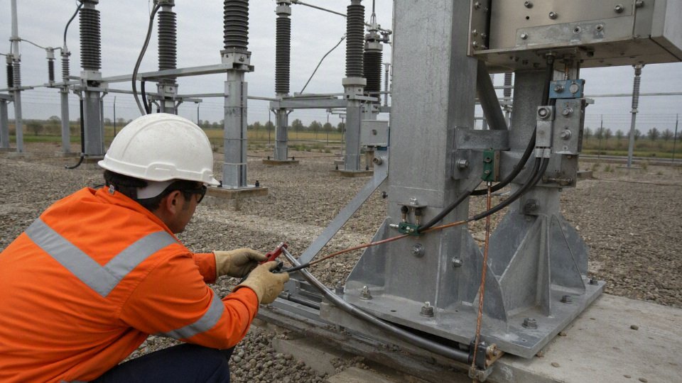
Touch voltage, step voltage, and transferred potential
Touch voltage is the voltage a person could experience between a hand on exposed metal and their feet on nearby earth or floor. Step voltage is the voltage between two feet separated on the ground surface. Transferred potential is the more awkward plant-floor case: a bonded cable sheath, conduit, fence, pipe rack, or remote enclosure brings a voltage rise from one grounding zone into another area where the local earth is at a different potential.
Ground potential rise occurs when fault current enters the grounding grid or earth and the grid impedance is not zero. Around medium voltage terminations, splices, link boxes, transformer tanks, switchgear frames, motor terminal boxes, junction boxes, and metallic support structures, that voltage can appear on surfaces people can touch. A plant may have a beautiful substation grid and still create exposure at a remote pump skid if the cable shield is bonded there, the skid ground is weak, and the fault return path drives the local metalwork above remote earth.
The review normally separates several exposure locations:
- Terminations at switchgear and transformers: check enclosure bonding, shield grounding tails, stress cone installation, and ground bus continuity. A loose lug on a braided shield lead is not a paperwork defect; it changes touch voltage and heat at the worst moment.
- Splices in handholes or vaults: verify shield continuity, splice grounding kits, water ingress protection, and whether personnel may access the structure during energized operation.
- Link boxes and sheath voltage limiters: check insulation, surge arrester condition, labels, and whether the box is touch-safe under fault and switching conditions.
- Cable tray and metallic supports: confirm whether the tray is intended as a grounding conductor, merely a support, or bonded for equipotential purposes. Those are not the same job.
- Remote equipment enclosures: compare local grounding electrode impedance against the source-end grid. Transferred potential can be the hidden issue on long feeders.
Applicable touch and step voltage criteria depend on the country, utility practice, site classification, fault duration, surface layer, footwear assumptions, and standard used for the grounding study. The safe approach is to model or test the grounding system using the project’s standard rather than applying a universal voltage value from memory. For procurement, that means the buyer should ask for cable metallic component data, but the site engineer still owns the grounding-grid and protection study.
Induced sheath voltage on long single-core runs
Single-core medium voltage cables introduce another problem: load current in each phase creates magnetic fields that induce voltage along nearby metallic sheaths, shields, armor, and bonding conductors. The effect increases with load current, cable spacing, route length, and unbalanced physical arrangement. Trefoil formation usually reduces induced sheath voltage because the three phase conductors are close and symmetrically arranged; flat formation can increase it, especially when phase spacing grows on ladder tray or in separate ducts.
Bonding method changes the operating result:
| Bonding arrangement | What it tends to do well | What must be checked |
|---|---|---|
| Single-point bonding | Avoids continuous circulating sheath current | Sheath voltage at the open end, surge protection, touch safety, link box insulation |
| Both-end bonding | Keeps sheath voltage low at ends and is simple to understand | Circulating current, extra losses, sheath heating, ampacity reduction |
| Cross-bonding | Reduces induced voltage and circulating current on long routes | Correct sectional lengths, phase transposition, link box wiring, maintenance discipline |
| Multiple bonding points | Can improve equipotential bonding in some layouts | Uncontrolled circulating currents and unclear fault-current sharing |
The trade-off is not academic. Both-end bonding may feel safer because exposed metal is tied down at both ends, but the circulating sheath current can heat the cable system continuously and reduce ampacity. Single-point bonding removes most circulating current, yet it can leave a hazardous sheath voltage at the isolated end if the route is long or the load high. Cross-bonding is elegant when designed and installed correctly; it is also easy to spoil with one mislabeled link box, one phase sequence error, or a maintenance crew that reconnects links “the way they looked before.”
Cable transposition and phase arrangement deserve attention before trays are fabricated. I have seen flat single-core circuits installed neatly with generous spacing because it looked serviceable, then the sheath voltage and losses became the problem. Tight trefoil cleats are less convenient for heat dissipation and pulling, but they often help magnetic cancellation. The best answer depends on ampacity, installation temperature, mechanical fixing under short circuit, pulling tension, maintenance access, and allowed sheath voltage.
This conclusion stops holding where the metallic screen is interrupted, jacket insulation is intentionally sectionalized, or bonding accessories are not rated for the induced and fault voltages. Long renewable collector circuits, mine feeders, and port crane supplies are typical places where the sheath voltage study should be treated as part of the cable design, not a late accessory detail.
Protection must clear the fault, not merely find metal
A grounding path has to help protective devices detect and interrupt faults within the intended time. Relays, fuses, reclosers, and breakers do not trip because a shield is grounded; they trip because enough measurable current, residual current, neutral current, voltage displacement, or directional signal reaches the protection scheme. The grounding design and protection design are one system.
A solidly grounded system may produce high ground-fault current, which makes detection easier but demands higher short-circuit withstand from shields, grounding conductors, terminations, and switchgear. A resistance-grounded system limits current, which can reduce arc-flash energy and equipment damage in some cases, but it also requires sensitive and reliable ground-fault detection. Ungrounded or resonant-grounded systems may keep a first fault operating for some time by design, yet they bring their own insulation stress, transient overvoltage, and fault-location discipline.
The counter-intuitive hazard is low fault current. People often assume lower current is always safer. Not if it is too low to operate protection quickly. A weak arcing fault through wet insulation, carbonized semiconductive layer, damaged termination, or contaminated splice may sit below an overcurrent pickup long enough to burn the shield, track across insulation, elevate exposed metal voltage, or convert a repairable defect into a cable replacement. The dangerous case is not always the biggest fault; it is often the fault the protection does not see soon enough.
For a medium voltage cable grounding review, I would expect the protection engineer and cable engineer to verify at least these coordination points:
- Minimum ground-fault current at the remote end is above the intended relay or fuse pickup with margin.
- Maximum ground-fault current near the source is within the withstand rating of the shield, armor, grounding conductor, terminations, splices, and bonding leads.
- Clearing time used in the thermal calculation matches the actual protective device curve, including backup operation if the primary device fails.
- Sensitive ground-fault protection is specified where the system grounding method limits current.
- Cable metallic paths are not unintentionally paralleled through tray, conduit, structural steel, water pipe, or communication bonding systems in a way that defeats the study.
- Terminations and bonding leads are installed as designed, with correct lug size, crimp tooling, bend radius, corrosion protection, and torque. A perfect calculation does not survive a loose tinned copper braid under a painted ground pad.
The commercial implication is straightforward: buying the cheapest shield construction without the fault study can move cost from the purchase order into outage risk, field rework, or larger grounding retrofits. Conversely, overspecifying every cable with a heavy concentric neutral or large separate grounding conductor can waste copper and complicate pulling when the protection and grounding study would have supported a leaner design. The right specification is the one that survives the calculated fault, clears fast enough, and keeps touch exposure controlled at the places people actually stand and work.
Cable designs and use cases
Cable construction usually tells you whether a separate ground wire is normal practice, merely optional, or not enough by itself. In medium voltage work, the grounded metallic shield is almost always part of the safety and insulation system, while the separate equipment grounding conductor is an installation choice driven by fault duty, bonding method, mechanical risk, and the rules for that plant or utility network.
Common MV cable constructions and what they imply
| Cable design or installation | Typical grounding arrangement | Where buyers get into trouble |
|---|---|---|
| Single-core MV cable | Copper tape shield, wire shield, lead sheath, concentric neutral, or a separate equipment grounding conductor, bonded per design | Treating the shield as a universal ground path without checking fault current, sheath voltage, and conduit or armor heating |
| Three-core MV cable | Individual or collective shields, fillers, bedding, armor if required, often with a grounding conductor or armor bonding | Assuming the armor automatically has enough continuity and fault withstand |
| Triplexed single-core assembly | Each phase shielded; shields or neutrals bonded according to circuit design | Long routes can develop induced sheath voltage if bonding is chosen casually |
| Aerial covered conductor | Often not shielded like a full MV power cable; grounding is handled through the line equipment and system design | Calling it “insulated cable” and expecting it to behave like shielded underground cable |
| Armored feeder | Shield plus armor bonding; sometimes a separate equipment grounding conductor | Steel armor around single-core AC cables can overheat if magnetic effects are ignored |
| MV tray cable | Shielded conductors with jacket suitable for tray use; grounding through shields, ground conductor, tray bonding, or a combination | Tray bonding continuity and termination bonding are often weaker than the purchase specification suggests |
| Mining, portable, or trailing cable | Grounding conductors and often ground-check conductors built into the cable | Using fixed-installation logic for a cable that is dragged, flexed, crushed, and handled by people |
| Submarine or underwater cable | Metallic sheath, armor, water-blocking layers, engineered bonding and earthing at landings | Corrosion, circulating currents, repair joints, and sheath losses can dominate the design |
| Direct-buried distribution cable | Concentric neutral, wire shield, tape shield, or jacketed neutral depending on utility practice | Neutral corrosion, poor splices, and unverified grounding at pad-mounted equipment |
Single-core MV cables are common in ducts, trays, tunnels, and large industrial feeders because they are easier to pull in heavy sizes and easier to route phase by phase. The catch is magnetic behavior. A single AC phase produces a changing magnetic field; if it is enclosed by ferromagnetic steel conduit, steel wire armor, or badly arranged steel supports, circulating currents and hysteresis losses can heat the metalwork. That heat is not theoretical. I have seen “mystery” ampacity problems traced back to one phase per steel conduit and bonding hardware that looked harmless on the installation drawing.
For that reason, single-core cables in AC service are normally installed with nonmagnetic armor where armor is required, or with all phases arranged so the magnetic fields cancel as much as practical. Aluminum wire armor, bronze armor, stainless grades selected for low magnetic response, or nonmetallic duct systems may be used depending on the standard and environment. The separate ground wire does not fix magnetic heating; it only provides a grounding path. If the cable geometry creates heating in steel, adding a ground conductor is not a substitute for correcting the raceway, armor, cleat, or bonding design.
Three-core MV cables are more compact electrically because the three phase currents sit in the same cable assembly and their magnetic fields tend to balance. They are useful for plant feeders, utility laterals, and installations where one pull is preferred over handling three large single-core cables. The trade-off is weight, bending radius, termination space, and repair difficulty. A three-core armored feeder may look tidy on a bill of materials, but in a congested substation basement a field crew may curse it for the entire pull.
Industrial feeders, machines, and substations
Industrial MV feeders to switchgear, transformers, motors, variable frequency drives, generators, and substations are usually engineered with explicit shield bonding and equipment grounding, not left to installer preference. The design review should match:
- available ground-fault current at the source;
- relay clearing time and backup clearing time;
- shield, armor, concentric neutral, or ground conductor short-circuit withstand;
- termination bonding continuity at every stress cone, elbow, pothead, and gland plate;
- touch voltage at exposed metalwork;
- induced sheath voltage on long single-core runs;
- grounding of skid-mounted equipment, motor frames, transformer tanks, and switchgear lineups.
Motor and drive feeders deserve special care. MV drives can introduce common-mode voltage, high-frequency components, and termination stress that differ from a plain transformer feeder. The cable shield still has to control the electric field around the insulation, but noise control, bonding impedance, and termination geometry may become more sensitive. A bare copper ground pulled beside the cable may help equipment bonding, yet it will not replace a continuous metallic shield around each phase insulation.
Generators and step-up transformers are another place where language matters. A buyer may ask for a “ground wire in the cable” when the protection engineer actually needs a fault-return path rated for a specific duty and a shield bonded in a particular way. Those are not the same procurement requirement. The purchase order should name the cable construction and the installation grounding requirement separately.
Renewable-energy collection systems
Solar collector circuits, wind turbine collection systems, battery energy storage systems, and step-up transformer feeders often use long MV routes with repeated terminations. Long routes increase induced sheath voltage, and repeated terminations increase the number of places where bonding can be missed, loosened, corroded, or landed on the wrong bar. In a solar plant, a mile of duct bank with pad-mounted transformers at intervals is not just “more cable”; it is more interfaces.
Renewable projects also have a commercial trap: the cheapest cable construction can shift cost into terminations, grounding studies, testing, and later troubleshooting. Concentric neutral or wire-shielded distribution-style cable may suit buried collector circuits. In tray, riser, inverter station, or skid work, a design may call for shielded MV cable plus a separate equipment grounding conductor sized by the governing code and fault study. The preferred choice flips when the installation changes from utility-style buried collection to plant-style equipment interconnection with exposed metal enclosures, cable tray, frequent maintenance access, and tighter touch-voltage expectations.
Battery energy storage adds another wrinkle: layouts are modular, dense, and changed late in the project more often than owners like to admit. Cable routes may pass through containers, skids, trenches, and outdoor switchgear in one feeder. That pushes the grounding design toward documented bonding points and inspectable continuity rather than relying on a buried metallic component no one can see after backfill.
Utility distribution and direct burial
Utility medium voltage distribution often uses concentric neutral cable, especially in North American-style underground residential or commercial systems. The concentric neutral can perform shielding, grounding, and neutral functions depending on the system design. Tree-retardant cross-linked polyethylene insulation, jacketed or bare neutrals, direct burial, duct banks, pad-mounted transformers, elbows, and sectionalizing cabinets all come into the same decision.
A concentric neutral is not automatically equivalent to a separate equipment grounding conductor in an industrial plant. Utilities may design around multi-grounded neutrals, specific protection philosophy, known transformer locations, and standardized accessories. A factory owner buying MV cable for a private substation cannot simply copy that construction unless the protection scheme, grounding system, and installation standard support it.
Direct-buried cable brings soil into the argument. Moisture, backfill quality, chloride exposure, stray DC currents, and jacket damage affect neutral corrosion and shield reliability. Jacketed concentric neutral cable can reduce corrosion risk but changes how the neutral contacts earth along the route. Bare concentric neutral may provide many earth contact points but can suffer in aggressive soil. Neither is universally superior; soil data, utility practice, fault levels, and inspection philosophy decide it.
A separate ground wire is always required for medium voltage cable.False
Medium voltage cable normally requires a grounded metallic shield or equivalent shielding system, but whether a separate equipment grounding conductor is required depends on cable construction, installation method, system grounding, fault duty, and the applicable code or utility standard.
Harsh environments and movable service
Mining, petrochemical plants, ports, tunnels, rail infrastructure, water treatment plants, and marine terminals tend to punish optimistic grounding assumptions. Corrosion attacks armor and glands. Vibration loosens bonds. Cable trays get modified during shutdowns. A contractor may replace a stainless gland with a plated one because it was on the truck. These details are not glamorous, but they are often where grounding continuity is lost.
Harsh-environment specifications may call for:
- galvanized steel wire armor, aluminum wire armor, or nonmagnetic armor depending on single-core versus three-core design;
- flame-retardant, low-smoke, low-halogen, oil-resistant, mud-resistant, or chemical-resistant jackets;
- water-blocked conductor and shield areas for wet ducts, ports, and tunnels;
- tinned copper grounding components where corrosion risk is high;
- flexible grounding conductors at equipment with movement or vibration;
- bonding jumpers around insulated joints, glands, or nonconductive sections;
- inspection points that maintenance crews can actually reach.
Portable and trailing MV cables are a separate class of thinking. They commonly include grounding conductors and ground-check conductors because personnel exposure, cable movement, crushing, abrasion, and plug-and-coupler handling are much more severe than in a fixed duct bank. The ground-check conductor allows monitoring systems to detect loss of grounding continuity and trip before a damaged cable becomes a shock hazard. That is why a mining trailing cable or shore-power cable may look overbuilt compared with a fixed feeder of similar voltage; it is built for abuse, not just ampacity.
The boundary is simple enough: cable construction can suggest the grounding method, but it cannot prove it. The final design still has to be checked against fault current, clearing time, shield or armor withstand, bonding layout, touch voltage, induced sheath voltage, and the actual installation environment. That is the difference between buying a cable that matches the catalog description and buying one that will survive the job.
Installation errors and failure modes
A medium voltage grounding design usually fails in service for ordinary field reasons: a shield is cut back too far, a bonding lead is left loose, a link box is wired differently from the drawing, or a jacket defect lets water work on the metallic screen for a few seasons. Most grounding-related MV cable failures are not caused by the concept being wrong; they are caused by the installed grounding path being discontinuous, underrated, overheated, corroded, or undocumented.
Shield discontinuity that breaks the intended fault path
Shield discontinuity is one of the first things I look for when a new circuit has odd test results, unexplained sheath voltage, or nuisance protection behavior. The shield or metallic screen is supposed to be a controlled conductive path, not a decorative layer under the jacket. If that path is interrupted, the cable may still energize, which makes the defect easy to miss until a fault, termination failure, or maintenance shock exposes it.
Common causes include:
- Poor termination workmanship
The semiconductive screen, insulation shield, copper tape, or copper wire shield is cut back incorrectly. A fitter trying to make a neat termination can remove too much shield length, nick insulation, or leave the shield with too little contact area for the grounding kit. Missing or poorly installed shield clamps
Some terminations rely on spring clamps, constant-force springs, soldered tapes, compression rings, or kit-specific grounding hardware. If the clamp is missing, undersized, or installed over contamination, the electrical contact may be intermittent.Cut copper shield wires
Wire shields are often folded back and gathered for connection. During stripping, it is easy to cut half the wires with a hook knife or side cutter. The cable may “look grounded,” but its effective shield cross-section and short-circuit withstand have been reduced.Loose copper tape shield connections
Copper tape shields need proper overlap, pressure, and bonding hardware. A loose wrap or a clamp placed over a wrinkled tape edge can heat under fault current and may not survive the specified clearing time.Improper splices
Splice kits have precise requirements for shield reconstruction. A splice that restores insulation but gives casual treatment to shield continuity is not a completed MV splice.Corrosion at shield or armor connections
This is common in manholes, wet cable trenches, coastal plants, cooling-water areas, and fertilizer or chemical facilities. A shield connection that tested fine at handover can become high-resistance after moisture and contaminants get under the seal.Unbonded link box components
Link boxes, sheath voltage limiters, removable links, and grounding bars must match the bonding design. A link box with the enclosure grounded but the internal bonding link left open is a classic commissioning headache.
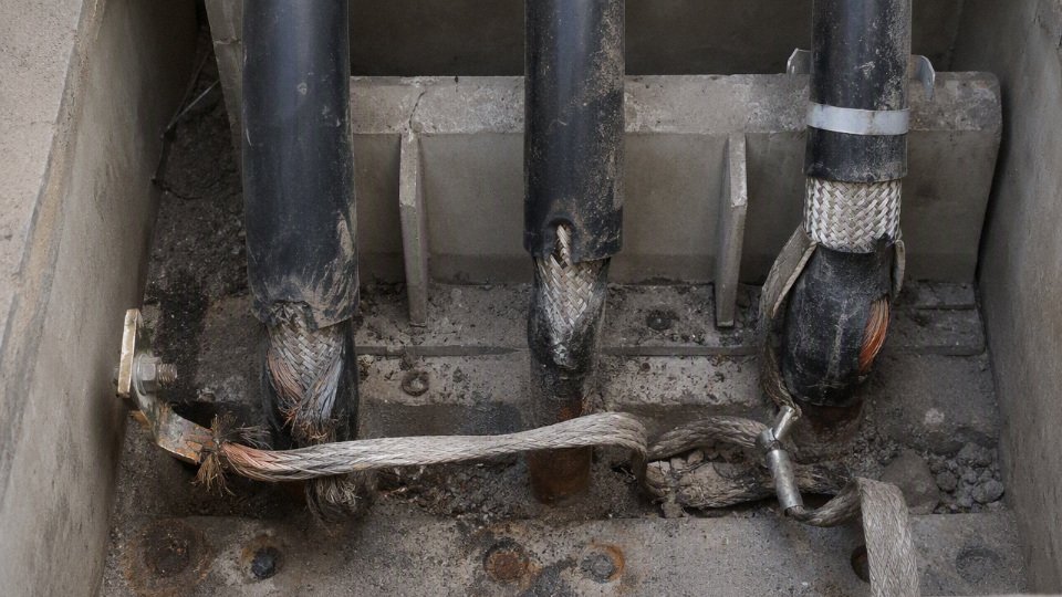
Floating shields and accidental bonding arrangements
A floating shield is not a harmless open wire. On an energized MV cable, the conductor-to-shield capacitance and magnetic coupling can raise the shield potential, especially on longer runs and single-core circuits. The result may be induced voltage on exposed metallic parts, small discharge activity at defects, or uncomfortable and sometimes dangerous touch voltage during maintenance.
Installation errors can accidentally create a bonding scheme nobody designed:
- A shield intended to be bonded at both ends is only connected at one end because a termination ground was missed.
- A single-point bonded system gets a second ground through a tray, gland plate, armor contact, or wet manhole bracket.
- A cross-bonded system is wired out of sequence in the link boxes.
- A sheath voltage limiter is installed but not connected to the intended shield segment.
- A temporary construction ground is left in place after commissioning.
The mechanism is simple enough: the shield voltage profile depends on where the shield is connected to earth and how it is coupled to the phase conductor. Change the connection points, and the voltage and current distribution changes. That may increase insulation stress at terminations, encourage partial discharge where there are voids or sharp screen edges, and put unexpected voltage on parts a technician assumes are grounded.
The trade-off is that some bonding methods intentionally leave parts of the shield isolated from earth under normal operation to reduce circulating current. That can be perfectly correct when sheath voltage limiters, sectionalized link boxes, warning labels, and test procedures are in place. It stops being acceptable when the field installation is not exactly controlled, because the safety margin depends on the designed isolation remaining deliberate, visible, and verified.
Bonding leads and lugs that cannot survive the duty
A bonding lead is part of the fault-current circuit. Treating it like a small control wire is a bad habit, and I have seen otherwise tidy switchgear rooms with long, looping shield pigtails tied up like instrument cable.
Watch for these defects:
- Undersized bonding leads with no verified short-circuit rating for the available ground-fault current and clearing time.
- Long pigtails that add impedance and create unnecessary voltage rise during a fault.
- Sharp bends near terminations, which can concentrate stress and make the lead harder to dress securely.
- Wrong lug material, such as aluminum lugs on copper shield wires without a listed transition method.
- Poor crimping, including the wrong die, single crimp where multiple crimps are required, or crimping over oxidized conductors.
- Incompatible metals exposed to moisture, causing galvanic corrosion at shield, armor, gland, or ground bar interfaces.
- No evidence of short-circuit withstand, especially where the cable shield is expected to carry fault current instead of a separate equipment grounding conductor.
A short, straight, correctly crimped bonding lead is not just neater; it reduces impedance and heating during the few cycles or seconds before protection clears. The preferred arrangement can change in cramped switchgear, retrofit vaults, and skid-mounted equipment, where mechanical routing constraints are real. In those cases, the engineer should verify the installed lead length, cross-section, lug type, and fault rating rather than assuming the standard detail was followed.
Jacket damage, water ingress, and corrosion
Outer jacket defects are easy to dismiss because the cable still passes load current. In direct-buried, duct-bank, tunnel, and wet-trench installations, that is a dangerous assumption. Once moisture reaches copper tape, copper wires, lead sheath, armor, or concentric neutrals, the grounding path can degrade slowly and unevenly.
The typical damage sources are predictable:
- Pulling damage from poor rollers, over-tension, sharp duct edges, or a damaged bell mouth.
- Backfill damage from stones, scrap metal, or careless compaction.
- Knife cuts during sheath removal at terminations.
- Water migration through poorly sealed ends before installation.
- Chemical attack from hydrocarbons, solvents, acids, alkalis, or contaminated groundwater.
- Rodent damage in trenches, substations, cable basements, and outdoor cabinets.
- Failed heat-shrink, cold-shrink, mastic, or gland sealing at terminations and splices.
Wet environments are not all the same. Clean water in a duct is one problem; warm, salty, chemically contaminated water sitting around dissimilar metals is another. The boundary here is material-specific: jacket compound, armor type, shield material, sheath construction, and sealing system determine how fast the problem develops, so this should be checked against the cable datasheet and the site exposure, not guessed from voltage class alone.
Circulating current overheating in single-core cable installations
Both-end bonding on long single-core MV cables can produce circulating current in metallic shields or sheaths. The current is driven by induced voltage from the phase conductors. If the phase arrangement, spacing, and bonding method are wrong, the shield may run hotter than expected even when the load current is within the conductor rating.
Installation errors that increase heating include:
- Bonding long single-core cable shields at both ends when the design assumed single-point bonding or cross-bonding.
- Installing phases too far apart, increasing magnetic coupling to the shield.
- Running phases in an unbalanced physical arrangement instead of trefoil or the specified flat formation.
- Using ferrous clamps around individual single-core cables.
- Passing individual phases through separate steel conduits or ferrous gland plates.
- Mixing cable routes so the three phases do not remain together.
Ferrous metal around one phase behaves like an unwanted magnetic circuit. It can heat badly, and it can also change the impedance balance of the installation. Non-magnetic clamps, trefoil cleats, proper phase grouping, and route discipline are not cosmetic details on single-core MV work.
Testing and commissioning mistakes
Commissioning should prove that the grounding system was installed, not just that the conductor insulation did not immediately fail. A common mistake is running the insulation test program while skipping the shield continuity and sheath integrity checks that would catch installation damage.
Practical checks should include:
- Verify shield continuity end-to-end before energization, including through splices and link boxes.
- Confirm bonding method against the design, not just against what is convenient in the field.
- Use the correct test voltage and method for the cable type, accessory type, and applicable standard or project specification. Inappropriate DC or excessive test voltage can create more trouble than it finds on some modern cable systems.
- Restore sheath voltage limiters and links after testing. If SVLs are disconnected for a test, they need a signed restoration step.
- Record baseline insulation resistance, sheath test results, continuity readings, and link box configuration so future maintenance has something to compare against.
- Inspect terminations physically after testing, because a passed electrical test does not prove that every ground braid, clamp, and lug is mechanically secure.
A medium voltage cable can pass an insulation withstand test while still having an unsafe or incorrect shield bonding installation.True
Insulation withstand testing primarily evaluates the insulation system under the selected test method. Shield continuity, bonding configuration, sheath voltage limiter restoration, and grounding conductor short-circuit adequacy require separate inspection, measurement, and documentation.
Documentation failures that create future faults
Bad records turn a correct installation into a future maintenance risk. The crew that installed the cable may know why one shield is isolated in a link box, but the maintenance electrician opening that box five years later during a shutdown may not.
The records that matter are not fancy:
- As-built drawings showing actual shield bonding points.
- Link box schedules with phase identification, sectionalizing points, SVLs, and removable links.
- Grounding conductor labels that survive dirt, ultraviolet exposure, and moisture.
- Termination and splice records showing kit type, installer, date, and test results.
- Procurement records listing shield type, shield cross-section, armor or sheath construction, and confirmed fault-current rating where applicable.
- Deviation records for any field change to bonding, phase spacing, cleat type, conduit material, or grounding conductor route.
This is where procurement and engineering overlap. If the purchase order only says “MV cable with copper shield,” the site team may not know whether that shield is adequate for the ground-fault duty, nor will the maintenance team have a clean basis for replacement. The cable, accessories, bonding hardware, and records need to describe the same installation; otherwise the plant inherits a grounding system that exists partly in copper and partly in someone’s memory.
Procurement specifications for buyers
Put the electrical duty on the purchase order, not only the cable name
A good MV cable inquiry starts with the system duty: voltage, insulation level, grounding method, fault level, environment, and installation route. If the RFQ only says “15 kV cable with ground wire,” the supplier has to guess whether you need a shielded power cable, a concentric neutral cable, an armored cable, or a cable assembly with a separate equipment grounding conductor.
At minimum, state these items clearly:
- Rated voltage and system voltage
- Nominal system voltage, such as 6.6 kV, 11 kV, 13.8 kV, 22 kV, or 33 kV.
- Cable rating, such as 5 kV, 15 kV, 25 kV, 35 kV, or IEC-style ratings like 6/10 kV, 8.7/15 kV, 12/20 kV, or 18/30 kV.
- Whether the system is phase-to-phase, phase-to-ground, resistance grounded, solidly grounded, ungrounded, or impedance grounded.
- Insulation level
- The required insulation thickness or insulation level according to the governing standard.
- Any special requirement for 100%, 133%, or other insulation category where that practice applies.
- Whether the feeder may operate for extended periods with one phase grounded.
- Conductor details
- Copper or aluminum conductor.
- Conductor size in mm², AWG, or kcmil.
- Conductor class: compact stranded, compressed stranded, flexible class, or sector-shaped where applicable.
- Any requirement for water-blocked conductor strands.
- Insulation and jacket material
- Insulation type, typically XLPE, EPR, or another project-approved compound.
- Outer jacket material, such as PVC, PE, LSZH, CPE, or other specified material.
- Flame rating, smoke and halogen limits, oil resistance, UV resistance, termite resistance, chemical resistance, or low-temperature flexibility if the site needs it.
- Installation method
- Direct buried, duct bank, cable tray, tunnel, riser, aerial messenger, substation trench, mine roadway, offshore module, or wind/solar collector system.
- Wet or dry location.
- Maximum ambient temperature, soil thermal resistivity if known, grouping with other circuits, and expected pulling route.
The mechanism here is simple but often missed: voltage class and insulation level protect against electrical stress, while jacket, armor, and water-blocking protect against the installation environment. Overspecifying every feature makes the cable expensive and stiff; underspecifying one environmental condition can leave a perfectly good electrical cable unsuitable for the route it is actually pulled through.
Define the metallic shield or screen without vague wording
The metallic shield is not a decorative layer. It controls the electric field, provides a path for charging current, supports fault-current return under defined conditions, and gives terminations a controlled interface. Buyers should specify the construction in measurable terms, not just “with screen” or “with grounding.”
Use one of these descriptions, depending on the cable design:
| Shield or metallic layer | What the specification should state | Procurement caution |
|---|---|---|
| Copper tape shield | Tape thickness, width if required, overlap percentage, helical application direction, total equivalent area if needed | Tape shields are common and compact, but fault-current duty must be checked rather than assumed |
| Copper wire shield | Number of wires, wire diameter, lay direction, spacing, total metallic area | Easier to calculate for fault current; can affect diameter, cost, and flexibility |
| Concentric neutral | Number and size of neutral wires, full neutral or reduced neutral, serving/binder details | Common in utility distribution; neutral duty and shield duty may be combined but must be engineered |
| Lead sheath | Lead alloy if specified, sheath thickness, corrosion protection, jacket over sheath | Strong moisture barrier, heavier and less flexible; handling and environmental rules vary by country |
| Armor | Steel wire, aluminum wire, steel tape, interlocked armor, or corrugated armor; armor bonding requirement | Armor may be mechanical protection, fault path, or both only if designed and bonded for that role |
| Combined design | Shield plus armor, shield plus separate ground, concentric neutral plus jacket | Avoid double-counting metallic area unless the bonding arrangement actually connects the parts in service |
The purchase specification should state the required metallic area and the intended function: electrostatic shield only, fault-current return path, neutral conductor, mechanical armor, or a combination. This is where many tender packages go soft. A supplier can manufacture several constructions that all look reasonable on a datasheet, but only one may match the protection study and the termination kits already selected by the EPC.
One practical example: a plant replacing old paper-insulated lead-covered feeder cable may ask for “same as existing, 15 kV, armored.” The old lead sheath may have been part of the grounding scheme. If the replacement uses XLPE insulation, copper tape shield, and steel wire armor, the grounding path has changed unless the armor and shield are intentionally bonded and rated. That change belongs in engineering review before the purchase order is placed, not during shutdown week.
State whether a separate equipment grounding conductor is required
A separate equipment grounding conductor, if required, should be specified as a conductor with a defined duty, not as a loose “ground wire.” State the material, size, insulation, position, color identification where applicable, and short-circuit withstand requirement.
Include these details:
- Copper or aluminum grounding conductor.
- Size in mm², AWG, or kcmil.
- Bare, covered, or insulated construction.
- If insulated, insulation and jacket color according to the applicable project or national rule.
- Whether it is:
- Laid up inside a multi-core cable assembly.
- Installed as a separate conductor in the same duct or tray.
- Integrated under the overall jacket.
- Supplied separately by the installer.
- Required fault current and clearing time.
- Whether it must bond armor, metallic shield, glands, trays, equipment frames, or all of them.
The trade-off is physical and commercial. An integrated ground conductor inside the cable assembly simplifies installation control because every drum contains the grounding path. It also increases cable diameter, weight, pulling tension, and minimum bending radius. A separately installed grounding conductor gives field flexibility and may be easier to replace or inspect, but it relies on the contractor routing and bonding it correctly. In tray work, I have seen the ground conductor take a different shortcut than the MV cable because someone thought it was “just ground”; that defeats the fault-current loop assumptions.
This guidance stops holding where the governing utility, mine authority, marine classification society, or national code mandates a specific grounding method. In those projects, procurement should not optimize the ground path independently; it should buy exactly the approved construction.
Give the supplier fault-current data, not just cable size
For MV grounding and shielding, the missing number in RFQs is usually ground-fault current. Cable suppliers can select copper tape, copper wires, concentric neutrals, armor bonding, and grounding conductors much more reliably when the protection data is included.
Ask the electrical engineer or protection contractor for:
- Maximum ground-fault current at the cable location.
- Fault clearing time, including breaker and relay operation.
- System grounding method:
- Solidly grounded.
- Low-resistance grounded.
- High-resistance grounded.
- Ungrounded.
- Resonant grounded.
- Relay settings if available.
- Required thermal withstand calculation for:
- Metallic shield.
- Concentric neutral.
- Armor.
- Separate equipment grounding conductor.
- Any touch-voltage or transferred-voltage limits required by the project.
Thermal withstand is not magic; it is a heat problem. Fault current passing through a metallic shield or ground conductor raises its temperature according to current magnitude, duration, material, cross-section, and starting temperature. Shorter clearing time allows a smaller metallic section for the same duty; longer clearing time pushes the design toward more copper, a separate ground conductor, or a different bonding scheme. The preferred choice flips when the cost of extra copper is lower than the risk and labor of complex bonding hardware, or when induced sheath voltage forces a cross-bonded or single-point bonded design.
A complete MV cable grounding review normally checks ground-fault current, clearing time, metallic shield or ground conductor withstand, bonding method, touch voltage, induced sheath voltage, and termination continuity.True
These are standard engineering review categories for shielded medium voltage cable systems, although the exact calculation method and acceptance limits depend on the applicable standard, system design, and project authority.
Specify bonding accessories and termination hardware as part of the cable package
Procurement should not treat accessories as a late-site purchase unless the plant already has an approved accessory standard. The best cable in the warehouse will still fail acceptance testing if the terminations, glands, shield breaks, and bonding kits do not match the cable construction.
List the required accessories or state who supplies them:
- Indoor terminations.
- Outdoor terminations.
- Separable connectors or elbows if used.
- Straight splices.
- Transition joints to existing cable types.
- Compression lugs and mechanical lugs.
- Cable glands for armored or unarmored cable.
- Shield grounding kits.
- Armor bonding kits.
- Link boxes.
- Sheath voltage limiters.
- Test leads for sheath testing or cross-bonding checks.
- Identification tags and phase markers.
- Heat-shrink, cold-shrink, premolded, or taped accessory technology, if the project standard requires one.
Small mismatch, big delay: a copper wire shield cable and a copper tape shield cable may need different grounding hardware at the termination. An armored cable entering a metal-clad switchgear gland plate may need both environmental sealing and armor bonding. If the gland is selected only by outside diameter, the installer may end up with a watertight gland that provides poor electrical continuity.
Require standards, tests, and factory records
The RFQ should identify the governing cable standard and the inspection documents expected with each shipment. Use the project standard rather than mixing requirements from unrelated systems. Typical references may include IEC, ICEA, AEIC, UL, national utility specifications, or plant engineering standards, depending on the country and end user.
A practical inspection and test scope may include:
| Test or document | Why buyers ask for it |
|---|---|
| Routine voltage test | Confirms basic insulation withstand on manufactured lengths |
| Partial discharge test, where applicable | Checks insulation system quality for shielded MV cable designs under the specified test condition |
| Conductor resistance | Verifies conductor size, material, and manufacturing consistency |
| Dimensional checks | Confirms insulation thickness, jacket thickness, shield construction, and overall diameter |
| Shield or screen continuity check | Confirms the metallic path is continuous before shipment |
| Jacket spark or integrity test, where applicable | Helps detect jacket defects that can compromise moisture or corrosion protection |
| Flame, smoke, halogen, or fire-performance tests if required | Supports plant, tunnel, building, marine, or transit requirements |
| Type test reports | Show that the cable design family has passed required qualification tests |
| Factory test report for each drum | Gives receiving inspection something concrete to verify |
| Material certificates and traceability records | Useful for export projects, utilities, and repeat procurement |
Be careful with partial discharge wording. Some MV cable standards define PD requirements very specifically, and some accessory systems have their own test regime. Do not ask for a generic PD value copied from another project unless the test voltage, sensitivity, cable length, and acceptance basis are aligned with the applicable standard.
Lock down logistics before production
Cable procurement fails in ordinary ways: a drum too large for the unloading area, a pulling length too long for the route, a jacket marking in the wrong language, or a bend radius that cannot be met inside an old substation basement. These are not engineering luxuries; they affect whether the cable can actually be installed.
Put these items into the purchase documents:
- Required drum lengths and allowable tolerance.
- Maximum drum outside diameter, width, gross weight, and lifting method.
- Pulling tension limits for conductor pulling and basket-grip pulling.
- Minimum bending radius during pulling and after installation.
- Sidewall pressure limit if the route has tight bends.
- Cable end sealing method for shipment and storage.
- Drum lagging, export packing, and moisture protection.
- Cable marking language, unit system, voltage rating, meter marks, production batch, and buyer project code.
- Certificates of origin or conformity if required.
- Inspection and test plan.
- Hold points or witness testing requirements.
- Type test reports and routine test reports.
- Traceability from raw material batch to finished drum.
- Spare length strategy for terminations, splices, and future repair.
For international jobs, documentation discipline saves weeks. A customs delay because the packing list does not match drum markings is not an electrical problem, but it still holds up energization. The same applies to certificates: agree on them before manufacturing, not when the forwarder is waiting at the gate.
How an integrated manufacturer can support bulk MV cable procurement
For repeat or high-volume MV cable orders, the buyer benefits when engineering, production, quality, commercial coordination, and after-sales support are connected rather than handled as isolated handoffs. Shandong Jinda Special Cable Group Co., Ltd., established in 1987, operates as an integrated cable manufacturer with R&D, production, sales, technical support, and after-sales service, five production bases, 470,000 m² of manufacturing space, and supply experience across more than 50 countries.
That matters most in these procurement situations:
- Multi-drum project supply
- Coordinating drum lengths, production batches, markings, and delivery sequence.
- Keeping cable construction consistent across repeat shipments.
- International documentation
- Aligning inspection documents, certificates, packing information, and project references with buyer and destination requirements.
- Grounding and shielding clarification
- Reviewing whether the requested construction uses copper tape shield, copper wire shield, concentric neutral, lead sheath, armor, a separate equipment grounding conductor, or a combined design.
- Technical-commercial trade-offs
- Comparing manufacturable options when the buyer needs lower pulling weight, higher metallic area, better moisture resistance, stronger flame performance, or simpler terminations.
- After-sales coordination
- Supporting questions that arise during receiving inspection, installation preparation, termination selection, or repeat ordering.
The most useful RFQ is not the longest one; it is the one that removes guesswork from the cable’s electrical duty, grounding function, installation environment, and acceptance documentation. For MV cable with grounding or shielding requirements, that clarity is usually worth more than another round of price-only negotiation.
Frequently asked questions
Does every medium voltage cable need a ground wire?
Not always as a separate insulated conductor, but a medium voltage cable normally needs a grounded metallic element or verified grounding path. That may be a copper tape shield, copper wire screen, concentric neutral, lead sheath, armor system, or a separate equipment grounding conductor.
The dangerous wording in purchase orders is “with ground wire” without saying what the ground wire must do. A small drain wire used to contact a tape shield is not the same thing as a fault-rated grounding conductor. For a 15 kV plant feeder, for example, the design question is usually:
- What metallic component controls the electric field around the insulation?
- What component is bonded to earth and equipment?
- What path carries ground-fault current until the relay or fuse clears?
- What limits touch voltage at terminations, joints, pull boxes, and equipment frames?
Those functions can be combined in one component on some systems, but not by assumption.
Can the cable shield be used as the equipment grounding conductor?
Only if the applicable code, utility rule, or project standard permits it, and only if the shield is proven adequate for the duty. The review has to cover continuity, impedance, fault-current withstand, corrosion resistance, and the way terminations and splices maintain the path.
A copper wire shield with enough cross-sectional area may look capable on paper, while a thin copper tape shield may be intended mainly for electrostatic shielding and fault detection rather than carrying a heavy fault for several cycles. The difference matters when a downstream termination fails and the protective device takes longer than expected to clear.
Engineers normally check:
- Available ground-fault current at the fault location
- Protective device clearing time, including backup clearing
- Metallic shield or screen cross-section and short-circuit rating
- Bonding jumpers across joints, terminations, and link boxes
- Corrosion exposure, especially in ducts, wet trays, direct burial, and coastal plants
- Whether the authority having jurisdiction accepts that component as the equipment grounding conductor
A medium voltage cable shield can always replace a separate equipment grounding conductor.False
The shield may perform that function only where the governing rules allow it and where its electrical, thermal, mechanical, and continuity performance is verified for the fault duty.
Should both ends of the shield be grounded?
Often yes on short, simple three-phase feeders, especially in industrial plants where both-end bonding gives a low-impedance path and keeps shield voltage close to ground potential. On long single-core circuits, both-end bonding can create circulating sheath currents that add heating and reduce usable ampacity.
The mechanism is straightforward: load current in the phase conductor induces voltage in the surrounding metallic shield or sheath. If the shield is bonded at both ends, that induced voltage can drive circulating current through the shield loop. The cable may still pass a megger test and look perfect, but it can run warmer every day, wasting capacity and aging insulation faster.
Common approaches are:
| Bonding method | Where it is commonly considered | Main concern |
|---|---|---|
| Both-end bonding | Short feeders, simple plant circuits, many three-core cables | Possible circulating current, usually manageable on short runs |
| Single-point bonding | Longer single-core circuits where sheath current must be avoided | Sheath voltage rise at the open end must be controlled |
| Cross bonding | Long transmission or collector circuits with sectionalized sheaths | Needs correct phasing, link boxes, surge protection, and testing discipline |
For a 30 m motor feeder inside a plant, both-end bonding is usually the boring and sensible answer. For a long wind or solar collection circuit, copying that habit without sheath-voltage calculations is asking for nuisance heating or unsafe standing voltage at link boxes.
Is a drain wire the same as a ground wire?
Usually no. A drain wire is commonly used to make reliable contact with a metallic tape, foil, or shield so the shield can be terminated more easily; it does not automatically qualify as an equipment grounding conductor or fault-current path.
This confusion shows up during stripping and termination. The installer sees a small bare copper wire under the jacket and treats it like the “ground.” In some cable constructions, that wire is only there to provide shield continuity and a convenient pigtail. Whether it can carry fault current depends on its size, material, construction, connection method, and the governing installation rule.
If a drawing requires an equipment grounding conductor, the purchase specification should call for it explicitly rather than relying on a drain wire discovered during installation.
Does cable armor count as grounding?
Sometimes, but only when the armor system, bonding hardware, glands, and continuity are rated and accepted for the grounding duty. Metallic armor may provide mechanical protection, a bonding path, or both, depending on the cable design and installation standard.
In practice, the weak point is often not the armor itself; it is the termination. A corroded gland, painted enclosure entry, loose locknut, or poorly fitted armor clamp can turn a theoretically continuous grounding path into a high-resistance connection. I have seen crews polish copper shield terminations carefully and then leave armored cable glands biting through paint with no bonding washer. The drawing was right; the installed path was not.
Verify armor grounding by checking:
- Armor type and material
- Short-circuit and earth-fault capability
- Listed or approved glands and termination kits
- Bonding jumpers where required
- Continuity through joints, boxes, and equipment entries
- Corrosion protection for the environment
What happens if a medium voltage cable shield is left ungrounded?
An ungrounded shield can rise to dangerous voltage, create shock risk, increase insulation electrical stress, promote partial discharge at defects, interfere with fault detection, and damage connected equipment. The failure may not be immediate, which is why this mistake sometimes survives commissioning and appears later as unexplained cable or termination trouble.
The shield is not decorative. In shielded MV cable, it helps define the electric field around the insulation. If it floats, induced and capacitive voltages can develop on the shield, especially on longer runs or near high-current conductors. A technician opening a termination box may then meet a shield that looks like grounded metal but is not actually at ground potential.
Symptoms can include:
- Tingling or measurable voltage on shield tails or link boxes
- Noise or unstable readings during testing
- Premature termination tracking
- Partial discharge activity at shield cutbacks
- Relay behavior that does not match expected ground-fault current
- Damage after switching surges or lightning-related events
If MV cable is installed in conduit, does the shield still need grounding?
Yes. The metallic shield or screen still needs proper grounding even when the raceway also serves a grounding function. The conduit may provide an equipment grounding path for the installation, but it does not replace the need to bond the cable shield according to the cable design and system grounding plan.
This is a common procurement and installation gap. The electrical contractor sees rigid metallic conduit or cable tray bonding and assumes the cable’s shield grounding is handled. It is not handled unless the shield is actually terminated, bonded, and tested. At MV terminations, that means using the correct stress-control kit, shield grounding braid or jumper, lug, and connection point specified by the accessory manufacturer and project drawings.
What information does a manufacturer need to recommend a grounding-related MV cable design?
A manufacturer needs enough system and installation data to distinguish shielding, grounding, neutral, armor, and fault-current requirements. Without that, the safest supplier response is usually a list of options rather than a single cable recommendation.
Provide at least:
- Voltage class, such as 5 kV, 15 kV, 25 kV, 35 kV, 6/10 kV, 8.7/15 kV, 12/20 kV, or 18/30 kV
- Applicable standard or project specification
- System grounding method and protection philosophy
- Available ground-fault current and clearing time
- Cable length and whether the circuit is three-core or single-core
- Installation route: tray, duct bank, conduit, direct burial, tunnel, mine, offshore, or indoor equipment room
- Required bonding method: both-end, single-point, cross-bonded, or to be engineered
- Environmental exposure, including water, chemicals, salt air, temperature, rodents, or mechanical abuse
- Whether armor, concentric neutral, copper tape shield, copper wire shield, lead sheath, or separate grounding conductor is preferred or mandatory
- Termination, joint, gland, and link-box requirements
Good cable selection starts before the purchase order. If the grounding path is left to be “coordinated on site,” it usually gets coordinated by the person with the least time and the fewest drawings.
Verify grounding before ordering
Use the grounding review as a procurement gate, not a late electrical comment on a cable data sheet. The right buying question is not only “does this medium voltage cable need a ground wire?” but whether the shield, armor, neutral, equipment grounding conductor, bonding method, accessories, and protection settings work together during normal load, ground fault, switching events, and maintenance.
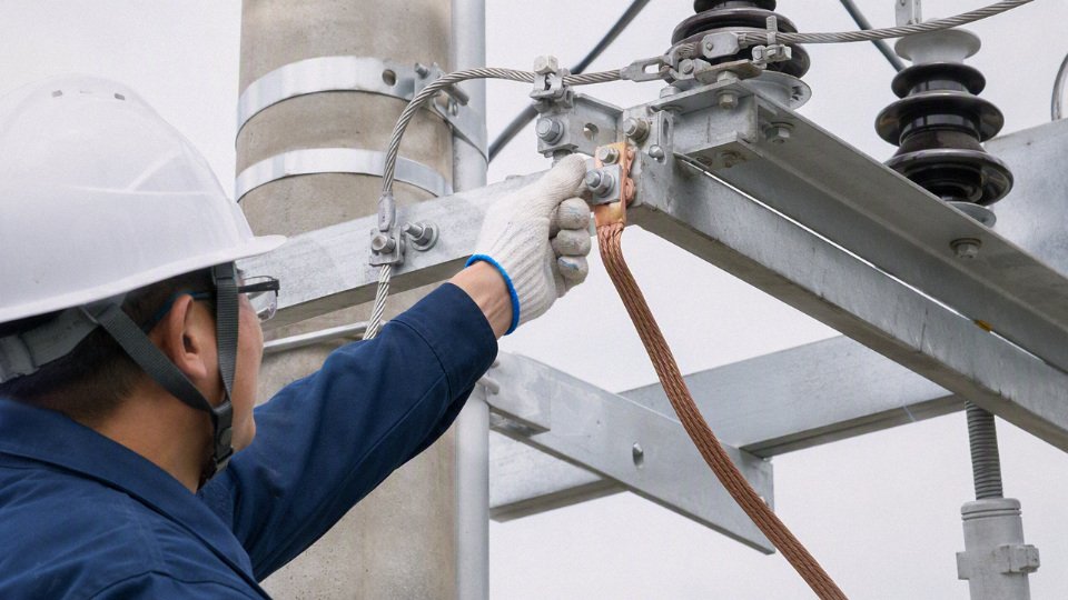
Gather the minimum engineering package
Before asking any cable manufacturer for a firm recommendation or quotation, collect the documents that define the fault duty and installation conditions. If these are missing, the safest supplier answer will be conditional, and the buyer may end up purchasing cable that fits the voltage rating but not the grounding duty.
Minimum inputs should include:
- Single-line diagram
- Source transformer or generator rating
- System grounding method: solid, resistance grounded, reactance grounded, isolated, or resonant grounded
- Switchgear, recloser, relay, and fuse locations
- Parallel feeders and tie points that may change fault contribution
- Grounding philosophy or earthing design basis
- Whether metallic screens are bonded at both ends, single-point bonded, or cross-bonded
- Whether armor is required as a grounding path or only for mechanical protection
- Whether a separate equipment grounding conductor is mandatory under the project standard
- Target limits for touch voltage and transferred potential
- Fault-current study and protection settings
- Available phase-to-ground fault current at the cable terminals
- Expected clearing time, including backup protection
- Relay curves, fuse curves, and any intentional ground-fault delay
- Maximum asymmetrical duty if the project standard requires it
- Cable schedule
- Voltage class, conductor size, conductor material, insulation type, and length
- Single-core or three-core construction
- Required screen type: copper tape, copper wire, concentric neutral, lead sheath, armor, or separate grounding conductor
- Spare drums, pulling sections, and joint locations
- Route layout and installation method
- Direct buried, duct bank, tray, tunnel, shaft, submarine approach, or aerial transition
- Trefoil or flat formation for single-core circuits
- Crossing points with other services
- Pulling tension limits, sidewall pressure concerns, and bend radius constraints
- Environmental and operating conditions
- Soil thermal resistivity, burial depth, ambient temperature, and seasonal moisture variation
- Chemical exposure, hydrocarbons, salt spray, UV, rodents, termites, or flooding
- Hazardous area requirements if applicable
- Expected continuous load, cyclic load, and emergency overload assumptions
- Applicable standards and owner specifications
- IEC, IEEE, ICEA, BS, AS/NZS, local grid code, mining standard, industrial owner standard, or utility purchasing specification
- Required test reports, factory inspection points, packing requirements, and delivery documentation
The mechanism is simple but often missed: ground-fault current heats the metallic return path according to current magnitude and clearing time, while bonding arrangement controls circulating current, induced sheath voltage, and touch-voltage risk. A screen that is acceptable for electrostatic shielding may not be acceptable as a fault-current return path, and a protection delay that looks harmless on the relay sheet can turn into excessive copper tape temperature during a cable fault.
Decide what grounding hardware is actually required
Once the engineering inputs are visible, the cable construction can be selected without guessing. In practice, this is where many purchase orders go wrong: the electrical design says one thing, the cable schedule says another, and the accessory list is copied from a previous project.
Confirm whether the project needs:
- A separate equipment grounding conductor, either in the same raceway, in the cable assembly where allowed, or installed alongside the feeder.
- A larger metallic screen than the minimum shielding screen, sized for ground-fault withstand rather than only electric-field control.
- A concentric neutral, common in some utility distribution systems where the neutral has both system and grounding functions.
- Armor bonding, especially for steel wire armor or metallic tape armor that may otherwise sit at an unsafe potential or carry unintended current.
- Link boxes, for single-point bonding or cross-bonding systems where sheath voltage management is part of the design.
- Sheath voltage limiters, selected to coordinate with expected induced voltage and transient duty.
- A specific termination or jointing kit, compatible with the insulation system, screen construction, conductor size, lug type, and bonding lead arrangement.
There is a real trade-off here. Bonding shields at both ends is simple, familiar to maintenance crews, and often robust for fault return, but it can create circulating sheath currents on single-core cables and reduce ampacity. Single-point bonding or cross-bonding can improve current rating by reducing sheath losses, but it adds link boxes, voltage limiters, labeling, testing steps, and failure points; it is not a good place to improvise with whatever is on the store-room shelf.
That preference stops holding where induced sheath voltage, touch voltage, or fault-duty requirements exceed the accessory ratings or the owner’s maintenance capability. A neat cross-bonding design on paper is poor value if the plant has no procedure for checking link box connections after cable pulling, flooding, or third-party excavation.
Check cable and accessories as one system
Do not buy cable, lugs, glands, terminations, joints, and link boxes as unrelated line items unless someone owns the compatibility review. Medium voltage insulation systems are not forgiving of mixed assumptions.
Check these interfaces before release for manufacture:
- Conductor material and lug type: copper-to-copper, aluminum-to-aluminum, or approved bimetallic arrangement.
- Conductor screen, insulation screen, and metallic screen dimensions against the termination kit range.
- Copper tape or wire screen cross-section against the fault-current calculation.
- Armor material against gland type, bonding clamp, corrosion exposure, and short-circuit duty.
- Outer sheath material against oil, sunlight, termite, flame, low-smoke, or abrasion requirements.
- Cable outside diameter against duct fill, cleats, glands, pulling grips, and sealing boots.
- Drum length against pulling route, joint bay locations, and site handling equipment.
- Factory test requirements against the standard named in the purchase order.
A common plant-floor failure is painfully ordinary: the cable arrives correct, the termination kit is “equivalent,” the bonding leads are too short for the gland plate layout, and the commissioning team has to fabricate a workaround under schedule pressure. That is how good engineering gets defeated by small procurement gaps.
Use approval checkpoints from purchase order to commissioning
Set review gates that match how cable projects actually fail, not just how they are drawn.
| Stage | Approval checkpoint | What to verify |
|---|---|---|
| Engineering release | Grounding and bonding design approved | Fault current, clearing time, screen or grounding conductor withstand, touch voltage, bonding method |
| Procurement | Cable and accessory specifications aligned | Cable construction, screen/armor/neutral requirement, termination and joint kit compatibility |
| Quality inspection | Manufacturer data and inspection plan accepted | Routine tests, type-test references where required, dimensions, marking, packing, drum schedule |
| Factory testing | Test records reviewed before shipment | Voltage test, partial discharge test where applicable, conductor resistance, sheath integrity if specified |
| Delivery | Documentation and drum condition checked | Packing list, certificates, drum numbers, cable ends sealed, damage inspection |
| Installation | Site records controlled | Pulling tension, bend radius, sheath test, bonding continuity, link box wiring |
| Commissioning | Energization package complete | Insulation test results, phasing, grounding continuity, protection settings, as-built bonding drawings |
The commercial decision is straightforward: specify the medium voltage cable only after the grounding path and protection behavior are confirmed as a system. That avoids overbuying copper where it is not needed, but it also prevents the much more expensive mistake of under-specifying the metallic screen, neutral, armor bonding, or grounding conductor.
For a technical specification review and quotation, send Jinda the project voltage class, route length and installation method, cable schedule, available ground-fault current and clearing time, bonding preference if already defined, required standard, and any owner specification. Clear route sketches, termination photos from the existing plant, or a sample specification are useful; with those inputs, Jinda can review manufacturing feasibility, align the medium voltage cable construction with the grounding requirements, and prepare a supply quotation for the project.