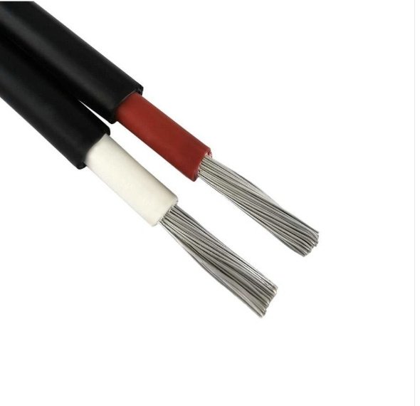
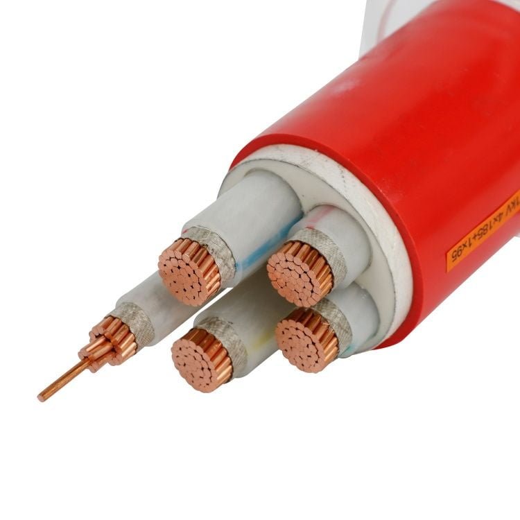
Specify the wrong cable and the plant pays for it — not once, but repeatedly. Undersized conductors overheat under load, insulation degrades faster than any datasheet predicts, and you end up chasing intermittent faults that only appear on hot summer afternoons when the ambient in the cable tray is already 45 °C. Oversize and you’ve wasted budget on copper you don’t need, plus you may not physically fit the termination into the switchgear cubicle. Both mistakes are more common than most procurement teams admit.
Power cables are classified by voltage rating — low-voltage (0.6/1 kV), medium-voltage (3.6/6 kV to 26/35 kV), or high-voltage (66 kV and above) — and by conductor cross-section, which runs from 1.5 mm² for light branch circuits up to 1,000 mm² for heavy feeders and busbar replacements. The right type and size depend on load current, installation method, ambient temperature, and the governing standard for the project’s country — IEC 60502, NEC, BS 7671, or AS/NZS 3008 being the most common.
What makes cable selection genuinely tricky isn’t the voltage class — that’s usually obvious from the system design — it’s the interaction between conductor size, insulation material, installation environment, and whichever standard the engineer of record has specified. A cable that passes every calculation on paper can still be the wrong choice if the procurement team doesn’t understand how those variables compound on an actual installation. The sections below work through each dimension in the order a plant engineer or procurement manager actually needs to think about them.
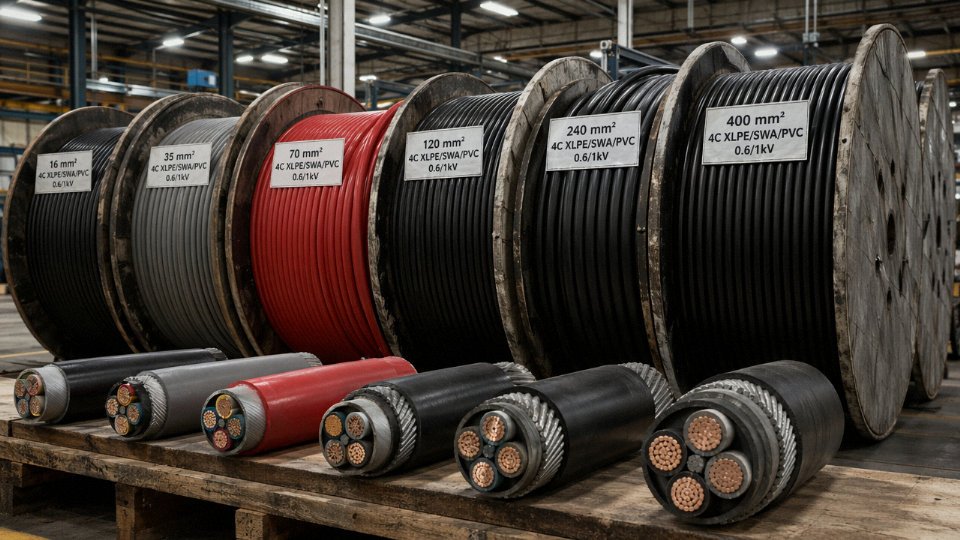
Core Power Cable Types: Insulation, Sheathing, and Construction Classifications
Walk into any cable warehouse and you’ll see dozens of drum labels — XLPE, PVC/SWA, EPR, LSZH — and it’s easy to treat them as interchangeable unless you’ve watched what happens when the wrong one gets installed. These classifications aren’t marketing categories. They describe fundamentally different physical constructions, each optimised for a specific thermal, mechanical, and chemical environment.
XLPE Insulated Cables
Cross-linked polyethylene has become the dominant insulation material for medium- and high-voltage cables over the past three decades, and it’s increasingly the default for modern low-voltage installations too. The cross-linking process — whether done by peroxide, silane, or electron-beam methods — converts the thermoplastic polyethylene into a thermoset structure that doesn’t soften and flow under sustained heat. Continuous conductor temperature rating sits at 90°C, with short-circuit thermal withstand reaching around 250°C depending on duration and cross-section. Dielectric loss is low enough that at transmission voltages it makes a measurable difference in system efficiency.
For MV and HV work, XLPE under IEC 60502-2 or IEC 60840 is essentially the default specification unless there’s a specific reason to deviate. At low voltage it competes mainly on thermal rating — a 95 mm² XLPE cable carries more current than the same physical size in PVC, which matters when you’re tight on conduit space.
PVC Insulated and Sheathed Cables
PVC cables are still the workhorses of building wiring and light industrial distribution, primarily because they’re cheap and easy to terminate. Continuous rating is 70°C for standard grades. That’s adequate for most final circuit wiring and a lot of panel cabling.
The limitations show up at the edges. Below roughly −5°C to −15°C (depending on plasticiser grade), PVC gets brittle enough to crack during installation — a real problem for outdoor winter work in northern climates. Fire performance is the other issue: PVC burns with heavy black smoke and releases hydrogen chloride gas, which is corrosive to electronics and toxic in enclosed spaces. For a factory production building with high ventilation, this may be acceptable. For a data hall, a tunnel, or a passenger-carrying vehicle, it isn’t.
EPR Insulated Cables
Ethylene propylene rubber gives up some of XLPE’s electrical efficiency in exchange for mechanical properties that no thermoplastic can match. EPR stays flexible at low temperatures, handles repeated bending without cracking, and resists water treeing and ozone degradation exceptionally well. In offshore and marine applications — where cables get flexed constantly by vessel movement and exposed to seawater spray — EPR is usually the right call. Mining trailing cables are another typical application, where the cable gets dragged across rock and through water on a daily basis.
Thermal rating for EPR runs to 90°C continuous, same as XLPE in most standards, though some specialised grades go higher.
PILC Cables
Paper-insulated, lead-covered cables are genuinely old technology, but anyone managing an urban distribution network built before the 1980s will still encounter them regularly. The impregnated paper insulation is hygroscopic, which is why the lead sheath exists — to keep moisture out permanently. Done right, a PILC cable in a stable environment can last 50–70 years. The problems come when the lead sheath gets damaged, when the installation involves significant changes in elevation (the impregnating compound migrates), or when you need to splice into it with modern equipment. Jointing PILC to XLPE requires specific transition joints and someone who actually knows what they’re doing.
Don’t expect to find PILC in new specifications. But don’t ignore it in legacy network assessments either.
Armoured Constructions: SWA, STA, and AWA
Armour is a mechanical protection layer, not an insulation system — that distinction matters at the design stage. Steel wire armour (SWA) adds tensile strength and crush resistance, making it suitable for direct burial, pulling through ducts under tension, or any installation where the cable might be struck or loaded mechanically. Steel tape armour (STA) offers crush protection but little tensile strength — it’s not the right choice for long duct pulls with significant pulling tension.
Single-core SWA has a specific problem: the steel forms a magnetic path around the conductor, and at AC power frequencies this generates eddy current losses that can be substantial in large-conductor cables. Aluminium wire armour (AWA) breaks that magnetic loop because aluminium isn’t ferromagnetic. For single-core cables above roughly 50–70 mm² in high-load circuits, specifying AWA instead of SWA is worth the cost difference in avoided losses over the cable’s service life.
Aluminium wire armour eliminates magnetic hysteresis losses in single-core AC power cablesTrue
Steel armour on a single-core cable forms a closed magnetic circuit around the conductor, inducing eddy currents and hysteresis losses at power frequency. Aluminium is non-magnetic, so AWA construction avoids this effect — a meaningful efficiency consideration on large-conductor cables carrying sustained high current.
FR and LSZH Cables
Fire-resistant (FR) and low-smoke zero-halogen (LSZH) cables address two different problems that often occur together. FR construction — typically a mica tape wrapped around the conductor bundle beneath the insulation — keeps the cable electrically functional during a fire for a defined period, usually 30–120 minutes depending on the standard and test conditions. This matters for emergency circuits: escape lighting, fire pumps, elevator recall systems.
LSZH compounds replace PVC and other halogenated polymers with halogen-free alternatives. The smoke they produce under fire conditions is dramatically less dense, and they release no hydrogen chloride or other toxic halogen acids. The practical cost is that LSZH compounds are generally stiffer and more sensitive to installation damage than PVC — installers used to PVC sometimes force bends that crack LSZH insulation, and this isn’t always visible.
In tunnels, offshore platforms, and public transport infrastructure, FR-LSZH specification is typically mandatory rather than optional. Getting the wrong cable installed in those environments isn’t just a compliance issue — it’s a life-safety failure waiting for an ignition source.
Voltage Rating Classes and How They Define Cable Architecture
Every IEC-rated power cable carries a designation in the form U₀/U — two voltages separated by a slash — and understanding what those numbers actually represent is the difference between specifying correctly and making an expensive mistake.
U₀ is the rated voltage between any one conductor and earth (or the metallic screen). U is the rated voltage between any two phase conductors. A 0.6/1 kV cable, for example, is designed for 600 V phase-to-earth and 1,000 V phase-to-phase. There is a third parameter, Um, that gets less attention in procurement conversations but matters to design engineers: it is the maximum system voltage the cable must tolerate continuously, accounting for grid fluctuations and regulation tolerances. For a 0.6/1 kV cable, Um is typically 1.2 kV. For an 18/30 kV cable, Um climbs to 36 kV. Exceeding Um — even briefly and repeatedly, as happens on poorly regulated rural feeders — degrades insulation over time through partial discharge activity. It does not always cause an immediate trip. It causes a failure eighteen months later that looks mysterious.
Low-Voltage Class: 0.6/1 kV
This is the workhorse of industrial and building electrical systems. Motor feeders, distribution boards, control panels, sub-distribution circuits, lighting circuits — nearly everything inside a facility runs on 0.6/1 kV cable. The insulation walls here are relatively thin: roughly 0.7 mm for a 1.5 mm² conductor and around 1.0 mm for conductors up to about 16 mm², per IEC 60502-1 tabulated minimums. Construction is straightforward — conductor, insulation, filler or binder, bedding, outer sheath, with armour added when the installation environment demands it. The electrical stress on the insulation is modest enough that semiconducting screens are not required. These cables are multi-core as standard; four-core and five-core configurations handle three-phase-plus-neutral and three-phase-plus-neutral-plus-earth layouts respectively.
Medium-Voltage Classes: 3.6/6 kV Through 18/30 kV
Step up to medium voltage and the physics changes. At these field strengths, any geometric irregularity on the conductor surface or at the insulation interface concentrates electric stress enough to initiate partial discharge — and partial discharge, sustained over time, erodes XLPE or EPR insulation reliably. The engineering solution is extruded semiconducting screens: one applied directly over the stranded conductor to smooth its surface, one over the outer insulation surface to create a defined, uniform field boundary. Both layers are typically 0.5–1.0 mm thick and are co-extruded with the insulation in a single triple-extrusion pass on modern lines, which eliminates the contamination risk that older two-pass processes carried.
Insulation wall thickness scales with voltage class in a way that is worth internalising. For XLPE per IEC 60502-2, expect roughly 4.5 mm at 6/10 kV, around 5.5 mm at 8.7/15 kV, and somewhere in the 8.0–8.5 mm range at 18/30 kV — exact values depend on conductor cross-section and the standard edition in use. That extra rubber means a noticeably stiffer, heavier cable. Installation crews on retrofit projects sometimes underestimate the pulling tension this generates in long conduit runs.
IEC 60502-2 covers medium-voltage cables rated up to 30 kV for fixed installationsTrue
IEC 60502-2 specifically addresses extruded insulation power cables and their accessories for rated voltages from 6 kV up to and including 30 kV, as defined in its scope clause.
The voltage classes in this range — 3.6/6, 6/10, 8.7/15, 12/20, and 18/30 kV — correspond to real grid voltage levels used in different national systems. A plant in a country running 11 kV distribution specifies 6/10 kV cable; one operating on a 20 kV network uses 12/20 kV. Matching the cable class to the actual system voltage is not optional. Running a 3.6/6 kV cable on a 10 kV system, even temporarily during commissioning, will cause insulation breakdown — not a warning, a failure.
High-Voltage Classes: 26/35 kV and Above
Above 30 kV, the governing documents shift to IEC 60840 (up to 150 kV) and IEC 62067 (above 150 kV up to 500 kV and beyond). The physical construction at these voltage levels looks substantially different from anything at medium voltage. Radial water blocking — a swelling tape or compound that seals the conductor interstices against longitudinal moisture migration — becomes standard, because moisture tracking along a conductor will destroy a cable from the inside in ways that are genuinely difficult to diagnose. Longitudinal blocking is added in wet or flooded installations.
Metallic screens at high voltage carry a defined short-circuit current rating, not just a screening function; the cross-section of copper wires or foil in the screen is calculated as part of the protection coordination study. Lead sheaths and corrugated aluminium sheaths are both used, the choice depending on the burial environment, installation length, mechanical handling requirements, and frankly, regional contractor preference. Jointing and termination at these voltages is highly project-specific and almost always involves factory-trained crews — the cable itself is only part of the system.
Specifying over-rated cable at any voltage class is a real cost, not a safe choice. A 6/10 kV cable where 0.6/1 kV is adequate adds material cost, requires larger conduit or duct, increases pulling complexity, and can create termination mismatches in switchgear cubicles designed for smaller cable entry. Under-rating, obviously, is worse — it ends in failure. Getting the voltage class right, matched precisely to U₀, U, and Um of the actual system, is the starting point for every other sizing decision.
Conductor Size Selection: Cross-Section, Ampacity, and the Standards Behind the Numbers
The first thing to understand is that conductor cross-section and ampacity are not the same thing, even though most engineers treat them as if they are. Cross-section is a physical dimension — the actual copper or aluminium area in mm², or the AWG/kcmil designation in North American practice. Ampacity is a calculated result that depends on that cross-section plus a half-dozen installation variables. Get one wrong and you either overheat insulation or massively overspecify cable, which on a 2 km feeder run adds real money fast.
mm² vs. AWG and kcmil: A Direct Size Comparison
IEC-based projects specify conductors in mm² per IEC 60228. North American NEC (NFPA 70) projects use AWG for smaller sizes and kcmil (thousand circular mils) for large conductors. These systems don’t map perfectly onto each other — a 4 AWG copper is nominally 21.1 mm², which sits between the IEC 16 mm² and 25 mm² preferred sizes. Always confirm which standard governs the project before issuing a purchase order; substituting the “nearest” size from the other system without checking ampacity tables has caused tripped breakers on commissioning day more than once.
| IEC (mm²) | Approx. AWG / kcmil equivalent | Typical copper conductor OD (mm) |
|---|---|---|
| 1.5 | 16 AWG | ~1.4 |
| 2.5 | 14 AWG | ~1.8 |
| 4 | 12 AWG | ~2.3 |
| 6 | 10 AWG | ~2.8 |
| 10 | 8 AWG | ~3.6 |
| 16 | 6 AWG | ~4.5 |
| 25 | 4 AWG | ~5.6 |
| 35 | 2 AWG | ~6.7 |
| 50 | 1/0 AWG | ~8.0 |
| 70 | 2/0 AWG | ~9.4 |
| 95 | 3/0 AWG | ~11.0 |
| 120 | 250 kcmil | ~12.4 |
| 150 | 300 kcmil | ~13.8 |
| 185 | 350–400 kcmil | ~15.3 |
| 240 | 500 kcmil | ~17.5 |
| 300 | 600 kcmil | ~19.5 |
| 400 | 750–800 kcmil | ~22.6 |
| 500 | 1000 kcmil | ~25.2 |
| 630 | ~1250 kcmil | ~28.3 |
| 1000 | ~2000 kcmil | ~35.7 |
OD figures are approximate and vary with stranding class and manufacturer tolerances.
Ampacity: What the Tables Actually Assume
IEC 60364-5-52 gives installation-method-based ampacity tables for low-voltage systems; IEC 60287 provides the underlying thermal calculation model used for medium- and high-voltage cables and for any non-standard installation geometry. Both start from a reference condition that rarely matches real plant conditions exactly.
A 95 mm² copper XLPE single-core cable in free air at 30°C ambient typically carries somewhere in the 250–270 A range. Bury the same cable directly in 20°C soil at the standard assumed thermal resistivity of 1.0 K·m/W and that figure drops to roughly 195–215 A. The spread within each range depends on conductor stranding class, sheath material, and whether the cable is touching adjacent cables.
Derating: Where Specifications Get Ignored on Site
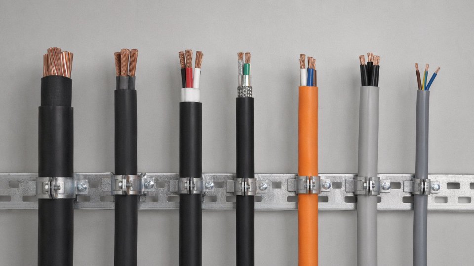
Derating factors are where real installations diverge from datasheet ratings, usually quietly and sometimes dangerously. Ambient air temperature above 30°C applies a multiplier — at 45°C that’s typically around 0.87 for XLPE-insulated cable, meaning a 270 A rated cable now delivers roughly 235 A usable capacity. Group together six cables in a conduit or cable tray without spacing and the grouping factor alone can push the derating to 0.60–0.70, which is a significant cut.
Other factors compound: burial depth beyond 0.7–0.8 m reduces heat dissipation; soil with high thermal resistivity (dry, sandy soil can reach 2.5–3.0 K·m/W versus the assumed 1.0) cuts ground-buried ampacity by another 15–25%; surface-laid cables in direct sunlight in hot climates need a solar radiation correction that most procurement specs in temperate regions forget to include. Each factor applied in combination means the installed cable may be operating at 60–65% of its catalogued rating — or conversely, that a poorly specified cable is being asked to run hotter than its insulation class allows.
Derating factors are multiplicative, not additive — applying three separate 0.9 factors gives 0.73, not 0.70True
Derating factors from IEC 60364-5-52 and IEC 60287 are applied as a product (0.9 × 0.9 × 0.9 = 0.729), not summed or averaged. Treating them as additive underestimates the total derating effect and leads to under-sized cables.
Voltage Drop: The Constraint That Forces You Up a Size
On short runs inside a switchroom, ampacity governs. On long runs — a 400 m feeder to a remote pump station, for instance — voltage drop takes over as the binding constraint. IEC and most national codes permit 3–5% voltage drop on final circuits and tighten that to 0.5–1% on transmission-level feeders. Running the numbers at 3% drop across 400 m at 200 A load often requires jumping from the ampacity-adequate 95 mm² up to 150 mm² or even 185 mm², depending on power factor. This is not rare; it is the normal outcome on any run longer than roughly 150–200 m at medium load currents. Procurement managers who simply copy the ampacity-based size from a short-run schedule and apply it to a long-run feeder will produce an under-sized cable that is perfectly legal thermally but chronically underperforms.
Short-Circuit Rating: The Adiabatic Check
Ampacity and voltage drop cover normal operation. Short-circuit rating covers the fault scenario, and it is non-negotiable. The standard adiabatic equation — S ≥ I × √t / k — links the required conductor cross-section S (in mm²), the prospective fault current I (amperes), the protective device clearance time t (seconds), and a material constant k that is 115 for copper with PVC insulation and 143 for copper with XLPE insulation. Aluminium takes lower k values, roughly 74–76 for PVC and 87–93 for XLPE depending on the standard used.
In practice, this check matters most where fault levels are high and clearance times are slow — older distribution systems with electromechanical relays set at 0.5–1.0 s, or long radial feeders where impedance reduces the fault current enough that fast fuses don’t operate quickly. A 35 mm² copper XLPE cable facing a 10 kA fault cleared in 0.5 s requires S ≥ 10,000 × √0.5 / 143, which gives roughly 49.5 mm², meaning the 35 mm² conductor fails the adiabatic check even if it passes ampacity. Always run both checks.
Copper vs. Aluminium: The Procurement Decision
Copper’s conductivity of approximately 56–58 MS/m versus aluminium’s 34–35 MS/m means that for the same current, copper needs a smaller cross-section — roughly 1.5–1.6 times smaller by area. Aluminium is about one-third the weight of copper at equivalent cross-section and costs significantly less per ampere-metre on large conductors above roughly 50 mm². For 240 mm² and above — substation feeders, main distribution trunks — aluminium often wins the cost argument clearly.
The catch is jointing. Aluminium oxide forms rapidly on exposed conductor surfaces and increases contact resistance if connectors rated for aluminium aren’t used. Bi-metallic lugs and correct crimping tools are not optional. In plants where maintenance electricians are more familiar with copper terminations, aluminium cable on small branch circuits tends to cause long-term reliability problems that copper would not. Above 50 mm², in dedicated feeder runs with competent jointing, aluminium is a practical and economical choice. Below that, copper is usually worth the premium.
Standard Cable Designations: How to Read IEC and National Code Cable Codes
Cable codes look like bureaucratic noise until you’ve chased down a wrong delivery because someone wrote “4-core 95mm² armoured” on a purchase order without specifying insulation material, voltage class, or standard. That shorthand is enough to get you three different cables from three different suppliers — all technically correct descriptions of very different products.
IEC and European Harmonised Codes (HD 361)
The German VDE-rooted designation system, harmonised across Europe under HD 361, reads position-by-position as a literal description of the cable’s construction. Take N2XY as a starting point:
- N — national base code (German VDE specification; cables manufactured to this origin standard)
- 2X — XLPE insulation
- Y — PVC outer sheath
Add an S and you get N2XSY: the S inserts a copper wire screen between the insulation and sheath, which moves this cable into medium-voltage territory where field grading and fault current return paths actually matter. N2XSY is a common designation for 6/10 kV and 12/20 kV single-core MV cables in European utility projects.
Other position codes worth knowing: A prefix means aluminium conductor (NA2XY); SE denotes a concentric neutral or screen arrangement in some variants; -J suffix signals a cable with a protective earth core, while -O means without one. The logic is consistent once you see it two or three times.
British BS Designations
British practice is more descriptive and less codified — you typically see the full construction written out in plain text with the standard cited at the end. A specification like 3-core 95 mm² Cu XLPE/SWA/PVC 11 kV BS 6622 breaks down as:
- 3-core — number of conductors
- 95 mm² — conductor cross-section per core
- Cu — copper conductor (Al would be stated if aluminium)
- XLPE — insulation type
- SWA — steel wire armour
- PVC — outer sheath material
- 11 kV — system voltage (note: BS 6622 uses Um notation; this cable is rated to 8.7/15 kV, applied on 11 kV nominal systems with appropriate earthing)
- BS 6622 — the governing construction and test standard
The BS format is verbose but actually friendlier for procurement: there’s less room for misinterpretation if the full string is written out. The failure mode is when engineers abbreviate to “11 kV SWA cable” and leave out the insulation system entirely.
North American NEC Type Codes
NEC cable types encode insulation material, temperature rating, and location suitability in a compact string. Key examples for power work:
- THHN — thermoplastic insulation, 90 °C dry locations, nylon jacket; standard building wire in conduit
- THWN-2 — rated 75 °C wet, 90 °C dry; the “-2” signals the higher dual rating, commonly required when conduit may see water ingress
- XHHW-2 — cross-linked polyethylene insulation, 90 °C wet and dry; better moisture resistance than THWN-2 in sustained wet environments
- MV-90 / MV-105 — medium-voltage cables rated to 90 °C or 105 °C conductor temperature; the numeric suffix matters when calculating ampacity under high ambient or bundled-conduit conditions
Chinese GB Designations Used in Jinda’s Manufacturing
GB/T standard cable codes follow a structured prefix-suffix logic that maps reasonably cleanly to IEC equivalents once you know the key letters:
- YJV — XLPE insulated (YJ), PVC sheathed (V); the direct functional equivalent of N2XY in European terms
- YJV22 — same as YJV but with double steel tape armour (the “22” suffix); used for direct burial or mechanical protection applications
- YJLV — aluminium conductor (L) XLPE/PVC; cost-driven selection for large cross-sections in industrial feeders
- ZC-YJV — flame-retardant class C (ZC prefix); for installations requiring BS EN 60332-3-24 equivalent fire performance
- WDZ-YJV — low-smoke zero-halogen XLPE/PE construction; specified in tunnels, public buildings, and offshore modules where toxic gas generation during fire is a rejection criterion
Jinda's GB-coded cables such as YJV22 and ZC-YJV are manufactured to standards that align with IEC 60502 construction and test requirements, enabling direct cross-referencing for international procurement.True
GB/T 12706, which governs YJV and related designations in China, is technically harmonised with IEC 60502-1 and IEC 60502-2 in its scope, test methods, and voltage class structure, making cross-reference viable with careful attention to any locally-specific requirements.
Why the Full Designation String Matters on Every Purchase Order
In practice, procurement documents frequently show only the cross-section and voltage — “3×95 mm², 11 kV” — which leaves insulation type, sheath material, armour type, conductor material, and applicable standard completely open to supplier interpretation. That ambiguity is fine when you’re buying from a single trusted supplier under an established spec. In open tendering across different national conventions, it routinely produces non-equivalent submissions.
A complete purchase order line should state: designation code, conductor material, number of cores and cross-section per core, voltage rating in U0/U format, applicable construction standard, and any special suffix (flame retardancy class, temperature rating, halogen-free requirement). That’s not bureaucratic overkill — it’s the minimum needed to get the same cable from five different factories.
Application-Specific Cable Selection: Buildings, Industrial Plants, Underground, and Renewable Energy
Getting the voltage class and cross-section right is only half the job. The other half is matching cable construction to the physical and electrical environment — burial depth, ambient temperature, mechanical exposure, fault current path, even UV exposure. The same 35 mm² copper conductor means something very different inside a commercial riser shaft versus a trench running under a road.

Commercial Building Distribution (400 V, 50 Hz)
Inside a modern office block or retail building, the primary concerns are fire behaviour and installation flexibility, not mechanical ruggedness. NYM-J cables work fine for final circuits in conduit, but where smoke toxicity matters — a hospital, a metro station, an airport concourse — N2XH LSZH construction is the right call and often a code requirement. Branch circuits to outlets and lighting typically run 2.5–4 mm², while distribution board feeders from the main switchroom to floor-level sub-boards step up to 50–150 mm² depending on floor load density and riser length. Above roughly 120 mm², you’re almost always pulling single-core cables in trefoil.
Armour is generally unnecessary inside cable trays or conduit in a building — it adds weight and cost without a real benefit. The exception is exposed runs in plant rooms or loading bays where mechanical damage is a genuine risk.
Voltage drop across long vertical risers can bite you if you calculate only for ampacity. A 70 mm² copper feeder that’s thermally fine can still land 4–5% drop on the top floor of a tall building if the run exceeds 80–100 m at full load. Check both.
Heavy Industrial Motor Feeders (6 kV to 11 kV)
A large process plant — a cement mill, a petrochemical site, a steel rolling line — will have dozens of medium-voltage motor feeders, often running in crowded cable trays through areas where ambient temperature regularly exceeds 45 °C. At that point, thermal derating isn’t optional; it can push you from 95 mm² up to 150 mm² copper for the same rated current.
N2XSY or equivalent screened XLPE single-core or three-core cable is standard here. The copper screen must be sized for the prospective earth-fault current and the clearing time of the upstream protection — a screen that’s adequate for a 0.5-second fault might fail in a system where backup protection trips at 3 seconds. Armour is worth specifying in tray runs near vibrating machinery; unarmoured cable in a tray next to a large reciprocating compressor will eventually chafe through its sheath.
Direct Buried Underground Distribution (11 kV to 33 kV)
Three-core SWA XLPE cable with aluminium conductor dominates this segment for cost reasons. Cross-sections typically fall between 185 mm² and 400 mm², sized primarily by sustained load current but checked against earth-fault loop impedance and short-circuit rating. Aluminium at 240 mm² is roughly equivalent in ampacity to copper at 185 mm², give or take a few amps depending on installation conditions.
IEC 60364 specifies a minimum burial depth of 0.75 m in public areas for underground distribution cables.True
IEC 60364-5-52 and related national implementations require minimum cover depths, with 0.75 m commonly cited for LV and MV cables in public or trafficked areas, increasing to 1.0 m under roads in many national codes.
Sand bedding beneath and above the cable — usually 50–75 mm each side — isn’t just good practice; it protects the SWA from backfill stones and distributes mechanical load. Marker tape at 250–300 mm below finished grade has saved more cables from excavator buckets than any other single precaution.
Offshore Wind Farm Array Cables (33 kV)
Submarine array cables connecting turbine foundations to the offshore substation are arguably the most demanding specification in this list. Static sections between fixed monopile foundations use lead-sheathed, galvanised steel wire armoured XLPE cable with copper conductors in the 95–185 mm² range. Dynamic sections at floating platforms face torsional cycling every few seconds — construction here requires a specific lay angle, controlled armour pitch, and often a bend stiffener at the touch-down point. Getting this wrong means fatigue failure within two to three years rather than the expected 25-year design life.
Longitudinal water blocking — either swellable tape or filled stranded conductors — is non-negotiable. A single pinhole in the lead sheath that lets seawater track axially can degrade insulation resistance along 20–30 m of cable before it shows up in a routine IR test.
Solar PV DC Cables (1.5 kV DC Class)
PV string cables live a hard life: UV radiation, temperature cycling from −25 °C to 90 °C on a dark roof in summer, and ozone exposure. Standard building cable sheathing compounds fail within a few years under these conditions. Single-core tinned copper cable with XLPE or EVA insulation and a UV-stabilised sheath, certified to TÜV 2 Pfg 1169 or IEC 62930, is the baseline.
Sizing follows the maximum string short-circuit current multiplied by 1.25 — that safety factor accounts for reflected irradiance conditions that can transiently exceed STC current. In practice this usually means 4–6 mm² for residential string runs and 10–16 mm² for commercial combiner box feeders, though longer runs on large ground-mount arrays may push to 25 mm².
Data Centre Power Infrastructure
A data centre is unusual because redundancy topology directly drives cable routing, not just cable size. N2XH LSZH cable is specified almost universally for the density of equipment and the consequences of combustion products affecting live electronics nearby. UPS-to-PDU feeders in the 10–95 mm² range are routed in overhead trays with physically separated A and B paths — a single tray fire shouldn’t take out both supply routes.
Voltage drop is tighter here than in most other applications. A 3% drop budget on a 400 V system leaves about 12 V of margin, and with UPS output tolerance already consuming part of that, the cable calculation gets constrained quickly. In my experience, data centre designs that start with a thermal sizing exercise and add voltage drop as an afterthought frequently end up upsizing conductors in the field — which on a 2,000-cable pull is an expensive correction.
International Standards, Certifications, and Quality Marks Buyers Must Verify
Specifying the right cable type and cross-section gets you halfway there. The other half is making sure the cable on the drum actually matches what the datasheet claims — and that requires understanding which standards govern what, which certification marks carry real weight, and where substandard product tends to hide.
The IEC Standards Stack and What Each One Covers
IEC 60502 is the workhorse for most procurement teams. Part 1 covers extruded insulation power cables up to 1 kV; Part 2 extends that to 30 kV. These specify construction requirements, test methods, and routine test protocols — not just design guidelines. IEC 60840 picks up from 66 kV to 150 kV, and IEC 62067 covers 150 kV through 500 kV and beyond. If a supplier quotes a high-voltage transmission cable but cannot produce a type-test report referencing IEC 60840 or 62067 by an accredited third-party lab, that is a serious problem, not a paperwork technicality.
Conductor class is separately governed by IEC 60228, which defines Classes 1 through 6 — solid, stranded, flexible, and so on. A conductor resistance value that barely scrapes under the IEC 60228 ceiling is worth scrutiny; it may indicate conductor cross-section that’s nominally correct but stranded loosely with excess die clearance.
The fire-performance standards matter enormously in building and tunnel installations. IEC 60332 (flame propagation — Parts 1, 2, and 3 for bunched cables), IEC 60754 (halogen acid gas emission on combustion), and IEC 61034 (smoke density) together form the minimum evidence set for any LSZH or fire-resistant cable claim. In practice, some suppliers test only Part 1 of IEC 60332 — single vertical wire — and omit the far more demanding Part 3 bundle test. Ask specifically which parts were tested.
Regional Standards That Buyers in Specific Markets Must Specify
Depending on where the cable is being installed, IEC compliance alone may not be sufficient or even the primary requirement.
| Market | Relevant Standards | Typical Certification Body |
|---|---|---|
| UK | BS 6622, BS 7835, BS 7671 | BASEC |
| Australia / New Zealand | AS/NZS 3008, AS/NZS 1125 | SAI Global, NATA-accredited labs |
| France | NFC 33-226 | LCIE, COFRAC-accredited labs |
| Germany | VDE 0276 | VDE Institute |
| North America | UL 44, UL 1072, NEC (NFPA 70) | UL, CSA |
| China (domestic supply) | GB/T 12706, GB/T 3956 | CCC mark via CNCA-approved body |
| Marine / Offshore | Lloyd’s Register, Bureau Veritas | LR, BV type approval |
For projects in Australia, AS/NZS 3008 ampacity tables differ from IEC 60364-5-52 in ways that matter — ground temperatures, soil thermal resistivities, and installation methods are locally calibrated. Using IEC tables uncorrected for Australian site conditions can result in undersized cables and thermal degradation within a few years of energization.
Third-Party Certification: What It Actually Proves
KEMA-KEUR (now part of DNV) type approval is among the more rigorous third-party validations for medium- and high-voltage cable. BASEC certification for UK-market cables involves both factory audits and product sampling — it is not a one-time test. UL listing requires follow-up inspections. If a supplier hands you a UL or BASEC certificate dated several years ago with no renewal documentation, verify current listing status directly on the certification body’s database. These are public registries.
ISO 9001:2015 is a minimum baseline for factory quality management — necessary but not sufficient on its own. Pair it with ISO 14001 if environmental compliance is part of your procurement criteria, particularly for halogen-free cable claims.
What to Request Before Placing Any Order
Routine test certificates (RTC) per IEC 60502 should accompany every shipment, not just the first one. These cover conductor resistance, high-voltage withstand, partial discharge (for medium-voltage cables), and insulation resistance — and the values should be comfortably inside limits, not skating the edge. Drum test records document per-reel traceability and are critical for large projects where reels may be installed across multiple circuits.
Factory audit reports from recognized third parties add another layer. Some buyers request cross-section micrographs of sample cable ends — actual insulation and sheath wall thickness measured against nominal tolerances. This is one of the bluntest, most reliable quality checks available, and a reluctant supplier is telling you something.
Jinda maintains a fully in-house testing laboratory capable of partial discharge testing, high-voltage withstand, conductor resistance, insulation resistance, and IEC 60332 flame-propagation testing, with test reports issued per IEC protocols and available for customer review.True
In-house testing capability at this scope is consistent with a manufacturer operating five production bases across China and holding active international supply contracts. Buyers should still request actual test reports and verify equipment calibration records.
Red Flags That Experienced Buyers Learn to Recognize
Absence of type-test reports is the obvious one. Less obvious: conductor resistance figures that consistently land at 99–100% of the IEC 60228 maximum allowable value across multiple test certificates. Statistically, a well-controlled production process produces results clustered well inside the limit. Results that cluster at the edge suggest the production target is set to pass the test rather than deliver performance margin.
Inconsistent insulation wall thickness — detectable from cross-section measurements — is another warning sign. IEC 60502 permits a minimum average thickness, but eccentricity (the insulation being thicker on one side than the other) affects both partial discharge performance and long-term service life in medium-voltage cables. Any supplier unwilling to share third-party audit results or who delays RTC delivery until after shipment has already cleared customs is not a supplier you want on a safety-critical project.
Cable Sizing Worked Example: Selecting Type and Cross-Section for a 400 V Industrial Feeder
This walkthrough uses a single realistic scenario to show how insulation type, burial conditions, grouping, and short-circuit duty all interact — and why the “obvious” first choice almost never survives derating.
The Scenario
A new motor-control centre rated 200 kW (three-phase, 400 V / 50 Hz) needs a dedicated feeder from the main LV switchboard. Cable run is 120 m, directly buried, soil temperature 25 °C, thermal resistivity 1.5 K·m/W. Two other feeders of similar size share the same trench. Future expansion is already planned, so the engineering team has agreed to design for 20% headroom above full-load current.
Step 1 — Design Current and Target Rating
Full-load current:
I = P / (√3 × U × PF × η) = 200,000 / (1.732 × 400 × 0.85 × 0.92) ≈ 369 A
Assuming power factor 0.85 and motor-drive efficiency 0.92 — both conservative but realistic for a VFD-fed MCC. Apply the 20% growth margin: target cable rating = 369 × 1.20 ≈ 443 A. That number is what the derated ampacity must meet or exceed.
Step 2 — First Cross-Section Attempt, Then the Derating Reality Check
From IEC 60502-1 ampacity tables, a 240 mm² copper XLPE 0.6/1 kV cable in free air carries roughly 460 A. Sounds adequate. It isn’t once you apply the burial factors:
| Derating factor | Value | Basis |
|---|---|---|
| Direct burial (from free-air) | 0.80 | IEC 60502 / manufacturer tables |
| Soil temperature 25 °C | 0.96 | Reference temp usually 20 °C |
| Grouping — 3 cables same trench | 0.82 | IEC 60287 / installation method |
Derated ampacity: 460 × 0.80 × 0.96 × 0.82 ≈ 290 A — well short of 443 A. This is the calculation step that catches out people who spec cable from free-air tables without adjusting for installation. It happens more often than it should.
Step 3 — Upsizing Through the Candidates
Move to 300 mm²: free-air rating roughly 520 A. Derated: 520 × 0.80 × 0.96 × 0.82 ≈ 327 A. Still insufficient.
Try 400 mm² copper: free-air ~590 A. Derated: 590 × 0.80 × 0.96 × 0.82 ≈ 371 A. Technically above 369 A actual load, but it only satisfies the base case — not the 443 A target with growth margin. At this point a pragmatic engineer might question whether the 20% margin is firm. If the MCC expansion is confirmed and funded, you need the next size up or you revisit the trench layout to reduce grouping.
Before jumping to 500 mm² copper, check 300 mm² aluminium. Aluminium free-air rating at this cross-section runs around 420–430 A depending on the table; derated it lands near 265–275 A, so it doesn’t solve the problem and conductor termination at the MCC busbar becomes a separate discussion. Copper it is.
Upshot: specify 400 mm² copper, 3-core, XLPE/PVC/SWA, 0.6/1 kV, unless the grouping can be loosened — say, staggering the third cable 300 mm away — which pushes the grouping factor closer to 0.90 and makes 300 mm² copper viable. Worth the conversation with the civil team.
Step 4 — Voltage Drop and Short-Circuit Check
Voltage drop for 300 mm² copper at 369 A over 120 m (used here as the alternative if grouping is relaxed): roughly 5.1 V, which is 1.3% of 400 V — comfortably within the 5% limit most standards permit for distribution feeders. Even 400 mm² at the same current produces negligible additional improvement; voltage drop is not the constraint here.
Short-circuit rating: prospective fault current at the MCC terminals is 25 kA, with upstream protection clearing in 0.1 s. The adiabatic equation (S = I × √t / k, with k = 143 for copper/XLPE) gives a minimum conductor cross-section of around 87 mm². Both 300 mm² and 400 mm² copper satisfy this by a wide margin — so short-circuit duty is not a driver in this case, though it should always be checked, especially on short runs close to transformers where fault levels can be high.
Final Specification
3-core 400 mm² copper conductor, XLPE insulated, PVC oversheath, steel wire armoured, 0.6/1 kV, IEC 60502-1. IEC designation: N2XY-J 3×400 mm² Cu. Order on drums of 500 m (one drum plus a short cut avoids a mid-run joint), and require a routine test certificate per IEC 60502-1 Clause 16 covering conductor resistance, high-voltage test, and insulation resistance as a minimum.
Applying derating factors for burial, soil temperature, and cable grouping can reduce a cable's free-air ampacity by 30–40% or more, meaning a cable that appears adequately rated in a datasheet may be significantly undersized in a real installation.True
This is consistent with IEC 60287 and IEC 60502 installation correction factors. Combined derating for direct burial, elevated soil temperature, and grouping of three cables typically yields a combined factor in the 0.60–0.65 range, reducing free-air ampacity by 35–40%.
One operational warning worth flagging: if the trench backfill uses low-density or poorly compacted material, the effective thermal resistivity can drift well above the assumed 1.5 K·m/W — towards 2.0 or even 2.5 in dry sandy soils. That alone can push the derated ampacity down another 8–12%. On projects where backfill quality is uncertain, specify thermal backfill (typically fluidised cement-sand mix) and confirm resistivity with a site test rather than assuming a textbook value.
Drum Lengths, Packaging, and Logistics Considerations for Large Cable Orders
Specification engineers spend weeks selecting the right conductor cross-section and insulation system, then hand the purchase order to procurement without a word about drum lengths. That’s where projects quietly go wrong — through avoidable joints, incompatible drum sizes, or containers held at customs because the wooden drums weren’t ISPM 15 compliant.
Standard Drum Lengths and Why They’re Not Arbitrary
Small cross-sections — typically 1.5 mm² through 16 mm² — are usually supplied in coils: 100 m, 200 m, or 500 m depending on conductor weight and how the product is marketed. These are light enough to handle by two people on site. Once you’re into 25–150 mm² territory, the cable goes onto full wooden drums, and standard traverse lengths run roughly 500 m, though this varies by manufacturer, insulation thickness, and drum barrel diameter. Treat “500 m standard” as a starting assumption, not a guarantee.
Large cross-sections — 185 mm² and above up to 630 mm² — get heavier fast. A 500 m length of 3-core 240 mm² XLPE armoured cable can weigh 7–10 tonnes on its drum, which already tests standard road transport. For 400 mm² and above, 300 m or even 200 m drums are often more practical, and some HV cables above 132 kV are limited to 100–200 m per drum purely by the physics of what a drum can safely carry and a road can legally support. Gross drum weights of 5–25 tonnes are a realistic range for medium and high-voltage cables; the upper end requires craneage and careful site planning that should be confirmed before the order is placed, not after the drums arrive.
Continuous Length Matters More Than Most Buyers Realise
For underground distribution feeders, cable joints are not just an added cost — they’re a long-term liability. A well-made joint is probably fine. A joint made under site pressure, in a wet trench, by a crew working to a schedule, is a failure point that can take out the entire circuit years later. The engineering logic is simple: fewer joints means fewer failure modes.
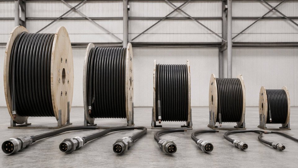
Specify minimum continuous drum lengths on your purchase order. If you have a 2 km MV feeder route, four 500 m drums is the right answer. Twenty 100 m drums means sixteen joints, and that should be unacceptable to any project engineer who has dealt with an underground fault on an energised network. Push back if a supplier quotes short lengths without a technical justification — sometimes it’s a manufacturing constraint, but sometimes it’s just inventory convenience.
Wooden vs. Steel Drums: A Practical Distinction
Most LV and MV cable ships on wooden drums, and that’s perfectly appropriate. For submarine cables and the heavier HV transmission cables, galvanised steel drums are standard — they withstand the mechanical stresses of laying equipment and offshore handling in ways wooden drums simply cannot.
What often gets overlooked is drum geometry. Flange diameter, traverse width, and barrel diameter need to be checked against site access: can your cable reel trailer handle a 2.8 m flange diameter? Does your substation entrance accommodate that drum without dismantling a gate post? These are not hypothetical inconveniences. Check crane capacity and road clearance constraints during the procurement phase.
Export Packaging and Sea Freight
International cable shipments require heat-treated wooden drums marked to ISPM 15 standard for phytosanitary clearance — untreated timber gets held or rejected at many destination ports, and the delays are genuinely painful.
ISPM 15-compliant heat-treated wooden packaging is required for timber export to most major importing countries including the EU, USA, Australia, and China.True
The International Standards for Phytosanitary Measures No. 15 (ISPM 15) is enforced at borders worldwide to prevent the spread of invasive wood pests. Non-compliant timber packaging is routinely detained or destroyed by customs authorities.
Beyond phytosanitary compliance, drums for sea transit need proper moisture-barrier wrapping — long voyages through humid shipping lanes, particularly trans-Pacific or Europe–Asia routes, will cause surface corrosion on steel armour and can compromise drum integrity if the timber absorbs water. Steel strapping to flat-rack or open-top containers is standard; confirm lashing points and stack weight limits with the freight forwarder before loading.
Jinda operates five production bases across China, which in practice means parallel manufacturing runs are feasible for large orders — you’re not waiting for one production line to finish before the next cross-section starts. In-house drum manufacturing keeps drum specifications consistent and IEC-compliant across the full order, and established relationships with major freight forwarders enable both FCL and LCL coordination for shipments to over 50 countries. For bulk international procurement, that integrated logistics capability reduces the coordination overhead that otherwise falls entirely on the buyer’s project team.
Frequently Asked Questions About Power Cable Types and Sizes
What is the most commonly used power cable type worldwide?
XLPE-insulated, PVC-sheathed cable — designated YJV under the Chinese/IEC system or N2XY under the European convention — is the dominant choice for both low-voltage distribution and medium-voltage feeders across most markets. The reasons are straightforward: XLPE handles sustained operating temperatures up to 90 °C (versus 70 °C for standard PVC insulation), resists moisture far better than paper-insulated designs, and has come down enough in cost over the past two decades that the old economic argument for PVC/PVC at low voltages barely holds anymore. For MV applications, the shift away from PILC accelerated once manufacturing quality for XLPE became consistent and IEC 60502-2 gave buyers a reliable benchmark to specify against. That said, PVC/PVC cable still moves in enormous volumes for interior building wiring and light industrial work, mostly because it’s cheap, available everywhere, and the load conditions don’t push the thermal limits.
How do I convert cable sizes between mm² and AWG?
There is no exact equivalence — AWG is a geometric series derived from wire diameter, while mm² is a direct conductor cross-sectional area. The two systems were developed independently and don’t align neatly. For practical procurement and design work, the closest pairings are:
| mm² | Nearest AWG / kcmil |
|---|---|
| 1.5 | 16 AWG |
| 2.5 | 14 AWG |
| 4 | 12 AWG |
| 6 | 10 AWG |
| 10 | 8 AWG |
| 16 | 6 AWG |
| 25 | 4 AWG |
| 35 | 2 AWG |
| 50 | 1/0 AWG |
| 70 | 2/0 AWG |
| 95 | 3/0 AWG |
| 120 | 4/0 AWG |
| 150 | 300 kcmil |
| 185 | 350 kcmil |
| 240 | 500 kcmil |
| 300 | 600 kcmil |
Never substitute blindly. Ampacity tables differ between IEC and NEC because the installation conditions, ambient assumptions, and derating methodologies are not the same. A 50 mm² cable to IEC 60228 Class 2 is not identical in performance to a 1/0 AWG cable sized per NEC 310. Verify ampacity against the applicable standard for your jurisdiction, not just the size conversion.
Can I use a higher voltage-rated cable on a lower voltage system?
Electrically, yes. The insulation wall on a 6/10 kV cable will handle a 400 V circuit without issue. Procurement teams sometimes do this deliberately to hold a single cable type across multiple voltage levels on a site — it simplifies inventory and reduces the risk of installing the wrong cable by mistake. The trade-off is real, though: a medium-voltage cable is physically larger, heavier, and stiffer than its low-voltage equivalent, which complicates cable tray fill calculations and makes termination work slower. It costs more per metre. Those are manageable consequences if the decision is intentional. Where it causes problems is when someone does it by accident — orders the wrong rated stock and installs it without checking — because the project team then finds out later during documentation review or third-party inspection, not during commissioning.
Using a cable with a higher voltage rating than the system voltage is electrically safe and does not degrade the cable's performance on the lower-voltage circuit.True
Insulation systems are designed to withstand at least the rated voltage; operating at lower voltage only reduces dielectric stress, which does not harm the cable. The practical downside is cost and physical bulk, not electrical safety.
What is the difference between a screened cable and an armoured cable?
These terms get mixed up often enough on purchase orders that it’s worth being precise. A screen is a metallic layer — copper tape, copper wire braid, or aluminium foil — applied directly over the insulation of individual cores or over the assembled cores. Its job in MV and HV cables is to control the radial electric field, preventing field concentration at irregular surfaces. It also provides a low-impedance return path for earth-fault current. Armour sits in the outer construction, typically steel wire armour (SWA) or steel tape armour (STA), and its purpose is entirely mechanical — resisting crushing loads, rodent attack, or tensile stress during direct burial or vertical installation. A cable can carry both a screen and armour (common in MV underground distribution), armour only (standard SWA low-voltage cable), screen only (some MV installations in cable trays with no crush risk), or neither. Confusing the two when writing a specification leads to either over-engineering or genuine safety gaps.
How long do power cables last in service?
XLPE medium-voltage cables designed to IEC 60502-2 carry a nominal design life of 30–40 years under normal operating conditions — meaning the cable is loaded within its ampacity rating, installed without physical damage, and not subject to sustained water ingress. In practice, service life depends heavily on installation quality. A cable with a damaged sheath buried in wet ground will begin degrading within a few years; a well-installed cable in a clean, dry duct can easily reach its design life. PILC cables in stable environments have sometimes remained in service for over 60 years, though utilities carrying aging PILC inventories will tell you that jointing becomes increasingly difficult as the mass impregnation dries out and the mechanical properties of the paper tapes change. Thermal cycling is the other major ageing mechanism — conductors that repeatedly reach maximum rated temperature stress the insulation more than cables running at moderate load.
What minimum order quantities and lead times should I expect?
For standard low-voltage cables in common sizes — say, 4-core 16 mm² to 185 mm² XLPE/PVC armoured — minimum orders are typically one full drum, which runs roughly 500 m for smaller sizes and 100–200 m for the larger cross-sections. Medium-voltage cable drums are commonly 100–500 m depending on cable weight and drum handling limits. Standard sizes held in stock can ship in 2–4 weeks from an established manufacturer. Custom specifications — non-standard voltage ratings, unusual conductor materials, specialized outer sheathing compounds, or MV/HV cables built to a specific national standard variant — typically require 8–16 weeks, and that range widens for genuinely large tonnage orders where production scheduling becomes a factor. Jinda’s five production bases operating in parallel allows large international project orders to run concurrent production runs, which matters when a single project requires several different cable types on the same delivery schedule. For procurement managers planning project cable packages, the practical advice is straightforward: don’t finalize drum lengths and delivery windows at the last stage of procurement. Get the technical specification locked early, confirm what the manufacturer holds in stock versus what requires production, and build the lead time into your project schedule before the civil works constrain your installation dates.
How to Partner with Jinda for International Cable Procurement and Long-Term Supply
If you’ve worked through a cable schedule for a real project — cross-sections, voltage classes, armoring requirements, applicable standards — you already know the next problem: finding a manufacturer who can actually deliver on all of it, not just the easy SKUs. That’s where manufacturing scope matters more than sales language.
What Jinda Actually Produces
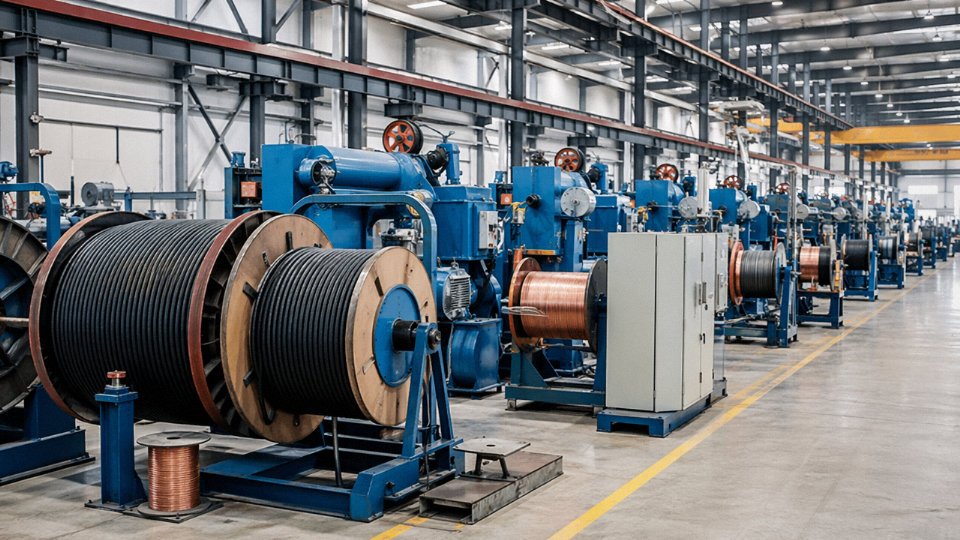
Jinda’s product range covers the full span discussed throughout this article. Low-voltage power cables from 1.5 mm² up to 1,000 mm², medium-voltage XLPE-insulated cables through 26/35 kV, and high-voltage cable solutions for transmission-level projects. Beyond the standard power cable range, the factory produces special-purpose cables — mining cables built to withstand mechanical abuse and methane-rated environments, marine cables with oil-resistant and flame-retardant sheaths, solar DC cables (TÜV 2 Pfg 1169 and IEC 62930 types), wind-turbine torsion cables, fire-resistant and circuit-integrity cables, and LSZH-sheathed cables for confined or public-occupancy spaces. Control and instrumentation cables are also in production — multi-pair, screened, with various armoring options. In practice, this means a single BOM covering a mixed industrial project can go to one supplier rather than being split across three or four.
Technical Support Before You Commit to a Purchase Order
This is the piece international buyers often underestimate, especially when they’re specifying to IEC or BS but the manufacturer quotes against GB standards. Jinda’s engineering team handles standard equivalence mapping — IEC 60502-1 to GB/T 12706, BS 6724 to its closest GB equivalent, UL-listed constructions where local code requires them. If your project spec says one thing and the factory’s standard datasheet says another, that gap needs to be resolved before production, not after the cable arrives at the port.
Cross-section sizing assistance is available at the pre-order stage. Submit your load data — demand current, route length, ambient conditions, installation method — and the team can run an ampacity and voltage-drop check against the relevant derating tables. Sample cables for pre-qualification testing can be arranged before full order commitment, which matters to any EPC contractor running a first-article inspection program.
Jinda provides IEC-to-GB standard equivalence mapping and pre-order sizing assistance as part of its technical support for international buyers.True
This capability is described by the manufacturer as a core service differentiator for international procurement, addressing a genuine gap that arises when IEC-specified projects are sourced from Chinese GB-standard manufacturers.
Quality Documentation and Third-Party Inspection
Production runs under ISO 9001:2015. For each project shipment, documentation available includes type-test reports, routine test certificates, material certifications for conductor, insulation, and sheath compounds, and factory inspection records. Third-party inspection through SGS, Bureau Veritas, or TÜV can be coordinated on request — useful when a project owner or lender requires independent hold-point inspections before despatch.
Supply Chain Depth and Lead-Time Management
Five production bases across Shandong Province totaling roughly 470,000 m² gives Jinda meaningful capacity to absorb large or time-critical orders without pushing everything to a twelve-week lead time. Raw material integration — copper rod, aluminum rod, PVC and XLPE compound produced or sourced in-house — reduces the external supply chain exposure that typically drives late deliveries on big cable packages.
How to Start the Conversation
Submit a cable schedule or BOM. It doesn’t need to be elaborate — cable designation, conductor material, cross-section, core count, voltage rating, required length per type, applicable standard, and delivery port is enough to generate a detailed quotation. Response time is typically 48–72 hours. For distributors and EPC contractors with recurring requirements, Jinda supports frame agreements, annual blanket orders, and consignment stock arrangements. Thirty-seven years of manufacturing experience and active supply relationships across more than 50 countries are reasonable indicators that the infrastructure for long-term partnership is genuinely in place — not just stated.