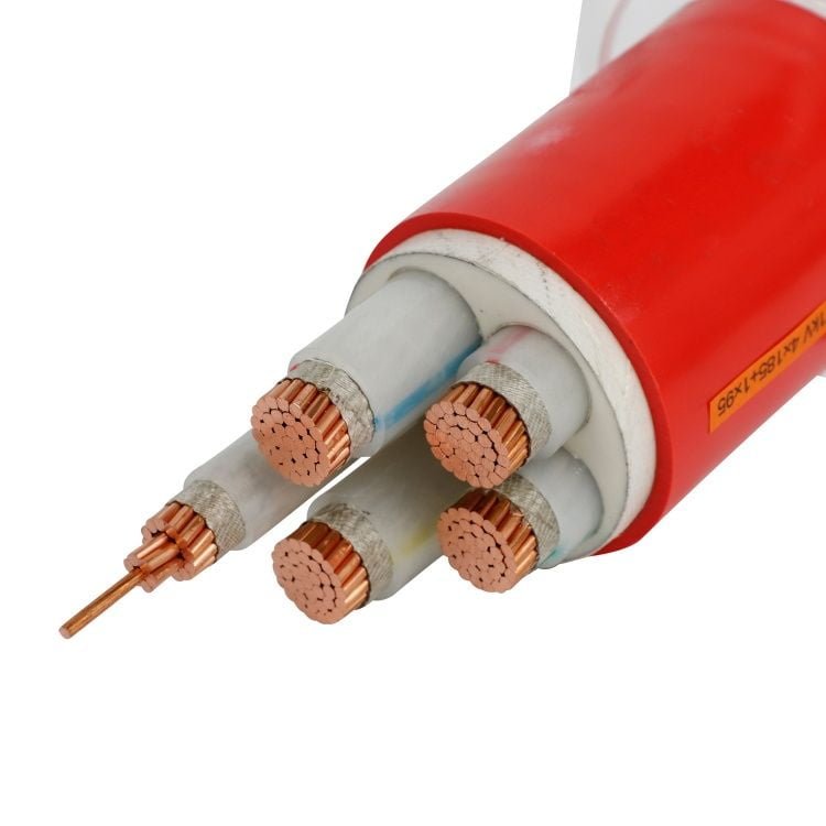
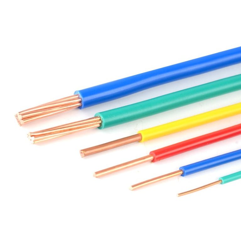
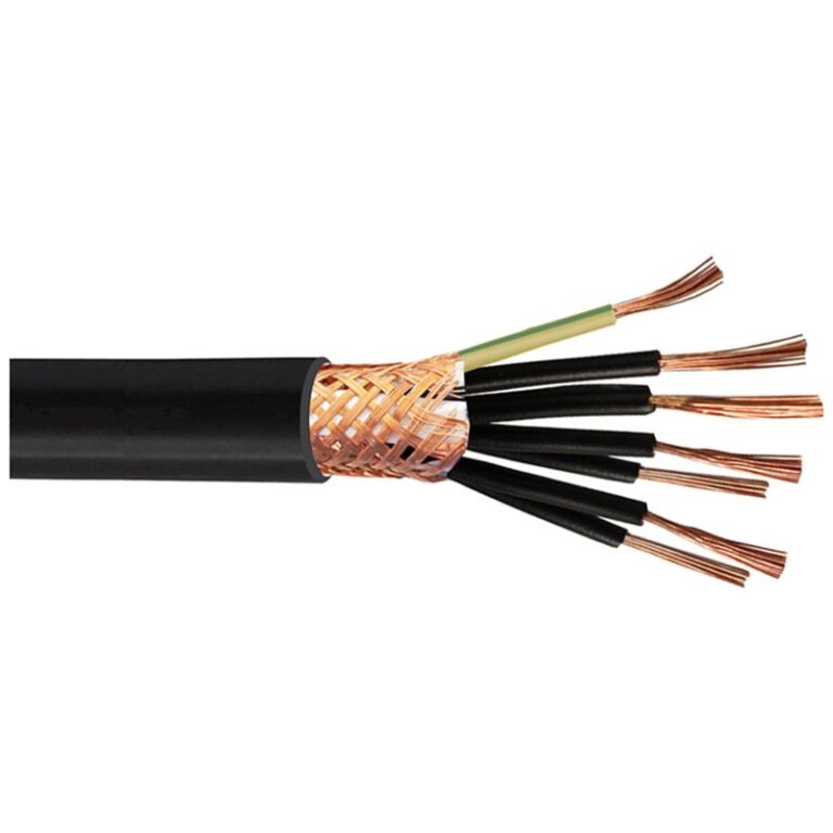
Specifying the wrong product — calling out “wire” on a purchase order when the application needs a rated power cable — shows up fast on the plant floor. You get undersized insulation that degrades under load cycling, conductors that can’t handle fault current, and a first failure that typically lands somewhere between a nuisance trip and a full feeder burnout. Rewiring a distribution panel or a machine tool enclosure mid-project can easily run two to four times the original material cost once you factor in labor, downtime, and the schedule hit.
A power cable is a multi-conductor or single-conductor assembly engineered for fixed electrical power distribution, with voltage ratings typically from 0.6/1 kV up to 500 kV, protective sheathing, and insulation systems designed for sustained load and fault conditions. A wire is a single conductor — bare or lightly insulated — used for internal equipment wiring or signal circuits, generally below 1 kV and in cross-sections rarely exceeding 35 mm². The two terms are not interchangeable in any specification that matters.
What makes this genuinely interesting is that the line between them shifts depending on who you ask — a panel builder in Germany, a utility contractor in Southeast Asia, and an OEM equipment designer all draw that boundary in slightly different places, and standards bodies like IEC and NEC don’t fully agree either. Understanding where the real engineering differences lie, and where the terminology just gets sloppy, is what keeps a procurement decision defensible.
Anatomy of a Wire: Construction, Materials, and Conductor Types Explained
At its most fundamental level, a wire is a single elongated conductor — one continuous metallic element, either solid or stranded — designed to carry electrical current. That’s the whole definition. No jacket assembly, no armor, no concentric layers of shielding. Just conductor and, in many cases, a thin dielectric coating or insulation. Understanding that simplicity is actually the point, because it defines what wire can’t do as much as what it can.
Conductor Materials and Conductivity
The three materials you’ll encounter in practice are electrolytic tough pitch copper (ETP), aluminum, and copper-clad aluminum (CCA).
ETP copper is the baseline. Annealed ETP copper sits at 100% IACS (International Annealed Copper Standard) — the reference against which everything else is measured. It’s ductile, easy to terminate, and resists corrosion reasonably well in most indoor environments. Aluminum runs at roughly 61% IACS, meaning you need a larger cross-section to carry the same current. That said, aluminum is substantially lighter and cheaper per kilogram, which matters enormously on long overhead runs or in large switchgear panels where weight is a design constraint.
CCA is the complicated one. Manufacturers sell it as a cost compromise, and sometimes it genuinely is. The problem shows up at terminations — CCA expands and contracts differently from pure copper under thermal cycling, and if someone uses copper-rated compression lugs without understanding what they’ve got, you’ll see resistance creep and eventually overheating at the connection point. Not a theoretical risk; it happens in panel shops that didn’t check the incoming material spec.
Annealed copper wire has an electrical conductivity of 100% IACS by definition, as the IACS standard was originally established based on the properties of high-purity annealed copper.True
The International Annealed Copper Standard (IACS) was defined in 1913 specifically using annealed copper as the reference material, so 100% IACS for ETP copper is definitionally accurate, not a rounded approximation.
Bare, Enameled, and Insulated: Three Very Different Products
Bare wire — no coating whatsoever — is used in overhead ground wires (OGW), grounding electrodes, and earthing mesh in substations. You’ll also see it as the drain wire inside shielded cables. It’s not a finished product for carrying load current in exposed installations; running bare copper as a circuit conductor in a panel would violate virtually every wiring code in existence.
Enameled wire, usually called magnet wire, is a different animal entirely. A thin polyester, polyurethane, or polyimide coating — sometimes only 0.02–0.05 mm thick — provides dielectric isolation while keeping the overall diameter tiny enough to wind hundreds of turns into a motor stator slot or transformer core. Voltage ratings for magnet wire are low, typically under 200 V turn-to-turn, but the thermal class matters far more: Class F (155°C), Class H (180°C), or Class C (220°C+) — the difference between a motor that survives a locked-rotor event and one that doesn’t.
Insulated single-conductor wire — PVC, XLPE, or PTFE jacketed — is what most people picture. Voltage ratings typically fall at 300/500 V or 450/750 V per IEC 60227, with some PTFE-insulated types rated to 600 V or 1 kV. PTFE variants handle temperatures up to around 200–260°C and resist chemical attack well, which is why you see them in oven wiring and aerospace panel harnesses. PVC is cheap and adequate for most dry indoor use; it gets brittle below roughly -15°C, something to remember if you’re wiring an outdoor enclosure in a northern climate.
Stranding Classes per IEC 60228
How the conductor is constructed — solid versus stranded — affects everything from current-carrying capacity to whether you can actually pull the thing through a conduit without it kinking.
IEC 60228 defines four classes relevant to power applications:
| Class | Construction | Typical Use | Bend Radius Consideration |
|---|---|---|---|
| Class 1 | Solid | Fixed building wiring, ≤16 mm² | Stiff; minimum bend radius 10× diameter |
| Class 2 | Stranded (compressed or circular) | General fixed wiring, cables | Moderate flexibility |
| Class 5 | Flexible (fine stranded) | Portable equipment, machine tool wiring | Tight bends acceptable |
| Class 6 | Extra-flexible (very fine stranded) | Welding cables, continuous flexing | Designed for repeated movement |
Solid conductors (Class 1) carry marginally higher current for a given cross-section in fixed installations because there are no inter-strand gaps. The difference is usually small — a few percent — but some designers prefer solid for that reason in high-load branch circuits. In practice, anything above 16 mm² solid becomes difficult to terminate cleanly; above 25 mm², it’s genuinely awkward to work with, and most electricians will push back on it.
Wire Gauges: AWG Versus Metric mm²
North American specs use AWG; the rest of the world generally uses IEC metric mm². The two systems don’t convert neatly because AWG is a logarithmic gauge derived from wire-drawing die steps, not a direct area measurement. Some quick working references: AWG 14 is approximately 2.5 mm², AWG 12 approximately 4 mm², AWG 10 approximately 6 mm², and AWG 6 approximately 16 mm². These are close enough for checking cross-section equivalence, but ampacity tables differ between NEC and IEC standards because installation conditions and insulation temperature ratings are assumed differently in each code.
Where Wire Actually Belongs
Wire is a component-level product. It lives inside control panels, motor coil windings, grounding systems, and low-voltage signal circuits. It is not engineered for direct burial, outdoor UV exposure without conduit, or installation in an environment where mechanical damage is plausible. When a procurement manager sources “wire” for a 35 kV feeder run, something has gone wrong upstream in the specification process — and that’s exactly the kind of confusion the rest of this article addresses.
Anatomy of a Power Cable: Layer-by-Layer Construction from Conductor Core to Outer Sheath
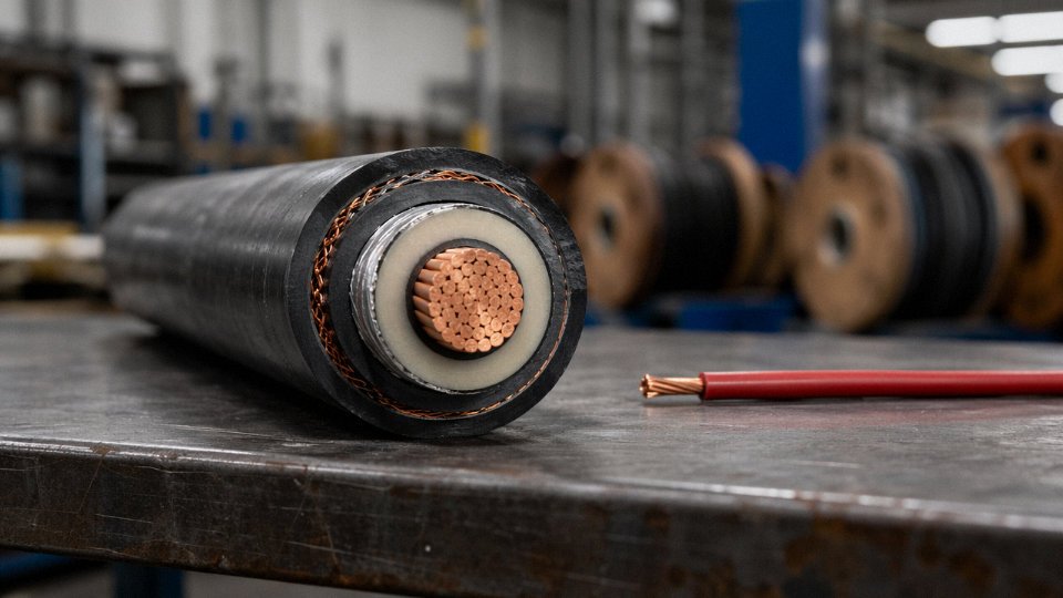
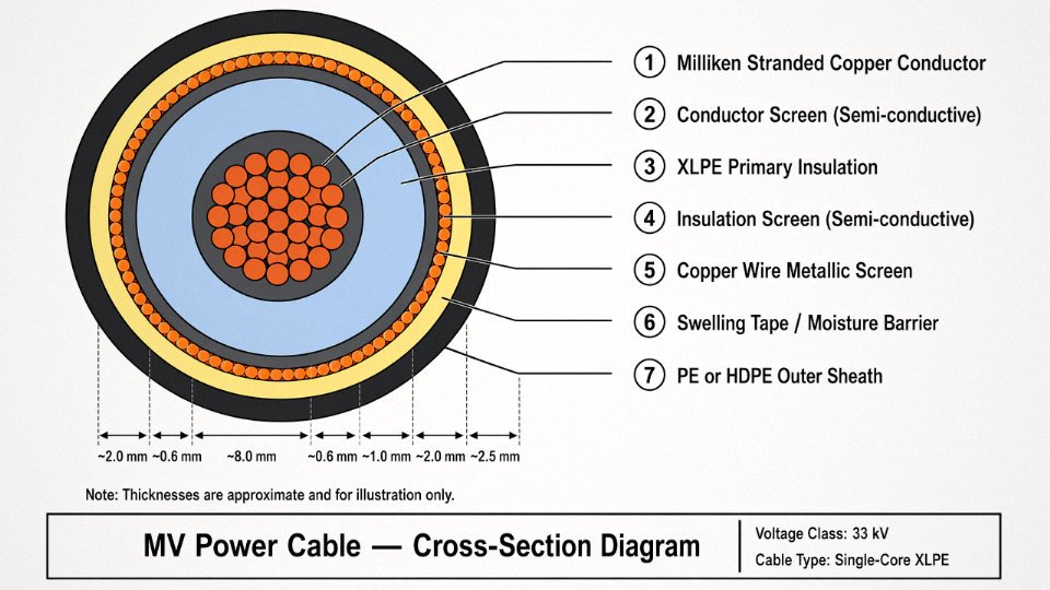
A power cable is not simply a larger wire. It is a deliberately engineered stack of materials, each layer solving a specific physical or environmental problem. Strip back a 33 kV XLPE cable on the workbench and you’ll count six or seven distinct zones before you reach the conductor. Each one is there for a reason — and specifying the wrong construction for your installation environment is how projects end up with premature insulation breakdown, nuisance earth faults, or catastrophic failures at the joint.
Layer 1 — The Conductor Core
Copper and aluminum are the same base materials you’ll find in hookup wire, but the conductor geometry changes significantly as cross-section and voltage class increase. Low-voltage cables below roughly 16 mm² typically use Class 2 stranded conductors — standard concentric lay. Above that, and especially above 95 mm², compacted-round or sector-shaped conductors become common because they reduce the overall cable diameter and improve packing efficiency in multi-core designs.
For large high-voltage cables — say, 630 mm² and above — Milliken construction segments the conductor into separately insulated sector elements twisted together. This directly addresses skin effect and proximity effect at 50/60 Hz, both of which would otherwise force current toward the outer surface of a solid or simple-stranded conductor and waste copper. Conductor cross-sections in power cable applications run from 1.5 mm² on residential branch circuits up to 2500 mm² for high-capacity transmission links; the right size depends on current rating, installation method, ambient temperature, and allowable voltage drop.
Aluminum costs roughly 40–60% less per unit weight than copper (the spread shifts with commodity markets), but its lower conductivity means you typically step up one or two cross-section sizes to carry the same current, and aluminum demands more careful jointing technique to avoid oxide layer resistance buildup.
Layer 2 — Conductor Screen
This semi-conductive layer appears on medium- and high-voltage cables starting at the 3.6/6 kV class. Its job is to create a smooth, uniform electric field gradient at the conductor surface. Without it, the irregular geometry of stranded wires creates local field concentrations — stress risers — that initiate partial discharge over time and eventually destroy the insulation from the inside out. In practice, cables below 1 kV omit this layer entirely.
Layer 3 — Primary Insulation
XLPE dominates modern MV and HV cable designs, and for good reason: it handles continuous operating temperatures up to 90°C and short-circuit temperatures up to around 250°C, it has excellent dielectric properties, and it resists moisture and chemical attack better than older oil-impregnated paper. EPR (ethylene propylene rubber) is the material of choice for flexible cables, mining cables, and marine applications where mechanical flexing or low-temperature performance matters more than the marginal dielectric advantage of XLPE. PVC insulation is limited to low-voltage work — it softens and loses its insulating properties above roughly 70°C continuous, so don’t let anyone specify PVC-insulated cable in a boiler room or industrial furnace feeder circuit.
XLPE insulation supports continuous conductor operating temperatures up to 90°C and short-circuit temperatures up to 250°C under IEC 60502 and IEC 60840 standards.True
These temperature limits are defined in IEC 60502-1 for medium-voltage XLPE cables and confirmed in IEC 60840 for HV cables; they govern current-rating calculations and are not marketing claims.
Layer 4 — Insulation Screen and Metallic Screen
Above 3.6/6 kV, a second semi-conductive layer — the insulation screen — wraps the outside of the primary insulation, mirroring the conductor screen and completing the controlled field environment. Over that sits a metallic screen, usually copper wires or copper tape. This screen serves three distinct purposes at once: it contains the electric field within the cable, it provides a low-impedance fault current return path back to the source, and it attenuates electromagnetic interference. The cross-sectional area of the copper screen is specified to carry the prospective earth fault current without overheating — undersizing it is a real procurement mistake on MV distribution projects.
Layer 5 — Fillers, Binders, and Bedding
Unglamorous but functionally important. In multi-core cables, polypropylene rope fillers or similar material pack the interstices between cores to maintain a circular overall shape, which matters for consistent armor behavior and conduit pulling. Moisture-blocking compounds or water-swellable tapes are often incorporated here in buried cable designs. The bedding layer — typically a non-woven tape or extruded compound — cushions the armor from cutting into the screen layers below.
Layer 6 — Armoring
Steel wire armor (SWA) is the standard choice for direct-buried and underground distribution cables. It handles tensile loads during installation and resists crushing from backfill settlement and ground movement. Steel tape armor (STA) is lighter and suits fixed installations in cable trays or ducts where mechanical impact risk is lower. Single-core cables present a problem with steel armor: the alternating magnetic flux from the conductor induces circulating currents in a continuous steel layer, creating eddy-current losses that can be surprisingly significant at high load — sometimes several percent of transmitted power. Aluminum wire armor (AWA) avoids this by using a non-magnetic material, and it’s the correct specification for single-core MV and HV cables as a result.
Layer 7 — Outer Sheath
The sheath is the cable’s first line of defense against the installation environment, and the compound choice should follow the actual site conditions, not the cheapest option that passed the basic flame test. PVC (ST1 or ST2 compound) is serviceable for most indoor and buried applications and offers reasonable chemical resistance. Polyethylene — particularly HDPE — adds UV resistance and is standard for direct-burial and submarine cable outer sheaths. LSZH (low-smoke zero-halogen) compounds are mandatory in confined spaces, tunnels, and occupied buildings where toxic halogen gas generation during a fire is the primary life-safety concern; they do cost noticeably more and are slightly less mechanically robust than standard PVC, which is a real trade-off worth acknowledging.
Extra-high-voltage cables at 220 kV and above add longitudinal water-blocking tapes and a corrugated aluminum sheath — essentially a metallic moisture barrier — between the insulation system and the outer jacket. At those voltage levels, water treeing in the insulation is the dominant long-term failure mechanism, and the construction reflects that.
A 0.6/1 kV power cable can be a relatively simple four-layer structure: conductor, PVC insulation, bedding, and PVC sheath. A 400 kV transmission cable is an eight-to-ten layer system where every material interface has been engineered to manage fields, heat, moisture, and mechanical stress simultaneously. Knowing which layers your application actually requires — and which ones you are paying for unnecessarily — is where specification competence translates directly into procurement value.
Voltage, Temperature, and Current Ratings: How Power Cables and Wires Are Classified Differently
The rating systems for wires and power cables are not just different in scale — they are different in kind. A wire carries a single voltage figure, sometimes a temperature suffix, and a tabulated ampacity. A power cable carries a voltage class, an insulation system design tied to that class, a thermal envelope that spans normal operation through emergency overload to fault conditions, and a short-circuit withstand rating that has to match the fault level of the actual system it feeds. Mixing these two frameworks up is how projects get rejected at commissioning or, worse, pass inspection and fail in service.
Wire Voltage Ratings: Simple Tables, Hard Limits
Most insulated hookup and building wire is rated 300 V, 600 V, or 1000 V. That figure refers to the insulation’s dielectric withstand, not to any system voltage class. UL-listed appliance wiring material might be 300 V PVC; a THHN building wire is typically 600 V; H07V-U under IEC is 450/750 V. Bare wire — stranded copper bus, tinned braid, bare aluminum conductor — carries no voltage insulation rating at all. Its electrical limit is purely thermal: current-carrying capacity set by cross-section and ambient temperature, using tabulated values rather than any field calculation. Trying to assign a voltage class to bare wire misunderstands what the product is.
Power Cable Voltage Classes and the Insulation Thickness Consequence
Power cables are classified in voltage classes that come in pairs — the first figure is phase-to-earth, the second phase-to-phase. Low voltage (LV) is 0.6/1 kV, the most common class for industrial plant distribution. Medium voltage (MV) runs from 3.6/6 kV up through 12/20 kV and 26/35 kV. High voltage (HV) covers 64/110 kV through 127/220 kV, and extra-high voltage (EHV) reaches 290/500 kV. IEC 60502-1 and -2 govern LV and MV construction; IEC 60840 covers HV up to 150 kV; IEC 62067 handles EHV above that.
Each class jump is not merely a label change. It mandates a specific minimum insulation thickness, a defined screen design, and for MV and above, a metallic layer to control the electric field. A 12/20 kV XLPE cable typically carries 5.5 mm of insulation on a medium cross-section; a 64/110 kV design will run 16–19 mm depending on conductor size. You cannot achieve HV performance by wrapping a wire in more tape. The geometry, the purity of the compound, and the extrusion process all matter.
IEC 60502-2 requires a semi-conductive screen over the insulation for all MV cables, not just HV designs.True
The IEC 60502-2 standard mandates inner and outer semi-conductive layers on the insulation for cables rated 6 kV and above to smooth the electric field and prevent partial discharge at the conductor surface — this is a fundamental MV design requirement, not optional.
Temperature Ratings: Where Wire and Cable Diverge Most Sharply
PVC-insulated wire is rated 70°C conductor temperature — practical for most panel wiring in normal ambient conditions. If you run it in a hot cabinet or bundle too many conductors together, you are already eating into that margin. Silicone-insulated wire extends to roughly 150–180°C, which is why it shows up in furnace wiring, motor lead connections, and automotive engine bays. Good silicone wire is noticeably more expensive, and the softer insulation requires careful routing to avoid abrasion.
XLPE-insulated power cable operates at 90°C continuously, can sustain up to 130°C under emergency overload conditions (typically defined as no more than a few hundred hours cumulative over cable life), and survives a short-circuit event up to around 250°C for the brief fault duration. That three-tier temperature envelope is fundamental to ampacity calculation under IEC 60287. PVC cable is rated 70°C continuous, 160°C short-circuit — noticeably tighter, which is why XLPE has largely displaced PVC in MV applications and in any LV run where loading is significant.
Ampacity: Calculation vs. Table Lookup
Wire ampacity in a panel is mostly a table lookup — pick the cross-section, note the ambient correction, apply a bundling factor if needed, done. Power cable ampacity is an engineering calculation governed by IEC 60364-5-52 for building/industrial installations and IEC 60287 for transmission and larger distribution work. The variables include conductor cross-section, insulation thermal resistivity, the cable’s installation method (direct buried versus duct versus tray versus air), soil thermal resistivity if buried, ambient temperature, and grouping with other loaded cables. A 240 mm² XLPE cable direct-buried in dry sandy soil at 35°C might carry meaningfully less current than the same cable in a concrete-encased duct bank with controlled backfill — the difference can be 15–25% in practice, depending on soil conditions and depth.
Short-Circuit Withstand: A Spec Point Wires Simply Don’t Carry
In a 11 kV distribution system, a switchboard fault level of 25–31.5 kA for one second is common. Power cable feeders to that switchboard must be specified to withstand that fault current for the stated clearance time without the conductor temperature exceeding the insulation’s short-circuit limit. That is a real procurement parameter — undersized cable conductors will anneal or fail their insulation in a fault event even if the upstream protection clears the fault quickly.
Panel wiring does not carry this burden in the same way. The upstream fuse or MCB is assumed to clear faults fast enough that the wire survives on account of the device, not its own withstand rating. The design responsibility sits with device coordination, not the wire specification itself.
Insulation Resistance: Different Standards, Different Meaning
A correctly installed and tested MV power cable should show insulation resistance well above 1000 MΩ·km when measured after installation. Values below a few hundred MΩ·km on a new installation are a red flag pointing to a damaged termination, moisture ingress at a joint, or a core that was nicked during pulling. Wire in a control harness or appliance wiring is typically accepted after a Hi-Pot test at twice the rated voltage plus 1000 V for one minute — a much simpler pass/fail screen that says nothing about long-term dielectric integrity, which is fine for the application but would be grossly inadequate as an acceptance criterion for a 20-year buried MV feeder.
International Standards and Certifications: IEC, UL, BS, and GB Requirements for Each Product
Standards are not paperwork formalities. A cable drum sitting in a warehouse without verifiable third-party certification is a liability — one that can get a project shut down, void an insurance policy, or worse, start a fire in a building tunnel where smoke density matters more than anyone anticipated during design.
Wire and power cable are governed by overlapping but distinct standard families, and confusing which standard applies to which product is a procurement mistake that shows up repeatedly on real projects.
Wire Standards
The foundation for conductor classification across almost every market is IEC 60228, which defines conductor classes 1 through 6 — basically ranging from solid conductors to very finely stranded flexible ones. Getting this wrong matters because a Class 2 stranded conductor and a Class 5 flexible conductor carry different resistance limits and flex-life expectations. Specifying the wrong class for a moving machine connection is the kind of error that causes fatigue breaks after 6–18 months of operation rather than immediately.
For PVC-insulated wires rated up to 450/750 V, IEC 60227 is the primary reference. Its rubber-insulated counterpart is IEC 60245, which covers applications with higher temperature exposure — think conductors inside industrial ovens or near furnace wiring trays. In the US market, UL 44 covers thermoset-insulated wires and UL 83 governs thermoplastic-insulated types; both carry mandatory UL listing marks that inspectors in North American jurisdictions will check on arrival at site. The UK legacy standard BS 6004 remains widely referenced for PVC-insulated cables and wires for domestic and similar installations, and even post-Brexit many UK project specs still call it out by number. China’s domestic equivalent is GB/T 5023, which aligns reasonably closely with IEC 60227 in structure but has its own dimensional tolerances and test sequences — relevant if you are sourcing from Chinese manufacturers and need to verify actual compliance rather than assumed equivalence.
Power Cable Standards
Low-voltage power cables up to 0.6/1 kV fall under IEC 60502-1. Medium-voltage cables from 1 kV to 30 kV are governed by IEC 60502-2, and the construction requirements — insulation thickness, screen design, oversheath — become substantially more demanding. Beyond 30 kV up to roughly 150 kV, IEC 60840 applies; above that threshold, IEC 62067 covers extra-high-voltage cables where type testing alone can run into significant project lead time. In the UK, BS 5467 and BS 6346 remain the specified standards for armored cables on infrastructure and utility contracts. For US medium-voltage applications, UL 1072 and UL 1569 are the relevant listings. China’s GB/T 12706 series mirrors much of IEC 60502 but again has its own test requirements, and the two are not automatically interchangeable on a project specification without explicit acceptance by the engineer of record.
Fire Performance — More Critical Than Most Buyers Appreciate
IEC 60332-1, -2, and -3 cover flame propagation — single cable through to installed bunches. IEC 60754 tests for halogen acid gas emission during combustion, and IEC 61034 measures smoke density. In European building and tunnel projects, EN 50575 and the CPR (Construction Products Regulation) require cables to carry a declared performance class from Aca down to Fca. Specifying a B2ca-rated cable for a data center raised floor versus a Fca-rated cable is not a minor upgrade — it is the difference between meeting building regulations and failing a fire safety audit.
Certification Marks and Red Flags
On a cable drum, look for KEMA or DNV type approval for high-voltage and subsea applications, Lloyd’s Register for marine cables, CCC mark for China domestic market, CE declaration for EU supply, and the UL listing mark for North American projects. Jinda maintains active certifications across these schemes for its export product lines, which matters when a project in Southeast Asia or the Middle East requires documented third-party evidence — not just a factory’s own test report.
Red flags worth treating as hard stops: missing or unverifiable third-party test certificates; print legends on the cable sheath that reference a standard but describe construction parameters inconsistent with it; conductor DC resistance exceeding the IEC 60228 maximum by more than roughly 2% (measurable in the field with a Ducter or Megger low-resistance ohmmeter); and insulation eccentricity outside the tolerances in the relevant standard, which you can check with a simple micrometer at cut cross-sections on delivery inspection.
IEC 60228 defines conductor resistance limits that can be verified with a portable low-resistance ohmmeter at goods receipt, making it a practical incoming inspection checkpoint rather than just a design parameter.True
IEC 60228 specifies maximum DC resistance per conductor class and cross-section at 20°C. A calibrated Ducter or similar instrument can confirm compliance on site without lab equipment, provided the conductor temperature is measured and the resistance is corrected to 20°C using the standard temperature coefficient formula.
A supplier who cannot produce test reports traceable to an accredited laboratory — not an in-house quality certificate — should raise an immediate flag, particularly for medium- and high-voltage cable where the cost of a failure dwarfs the cost of the cable itself.
Application Mapping: Matching the Right Product to Power Generation, Transmission, Building, and Industrial Use Cases
Getting the application match right isn’t just a specification exercise — pick the wrong product and you’re looking at premature failure, a voided warranty, or in the worst case, a fire. The categories below map real environments to the cable and wire constructions that actually survive them.
Power Generation — Renewable Energy
Solar DC strings are a common source of mis-specification. Installers sometimes pull standard flexible wire from stock because it looks similar to EN 50618 / IEC 62930 solar cable. It isn’t. Genuine solar cable is a single-conductor construction rated 1.8 kV DC, cross-linked insulation (usually XLPE or EVA compound), and UV-stabilized outer sheathing that holds up after 25-plus years of direct sun exposure in desert or coastal conditions. Standard flexible wire will chalk, crack, and track to ground within a few seasons. Conductor size typically runs 4 mm² to 6 mm² on residential string wiring, climbing to 35 mm² or higher on commercial DC trunk runs depending on string length and inverter input current.
Wind turbine tower cables are a different problem entirely. The cable has to survive continuous torsional cycling as the nacelle yaws — standard power cable construction, with rigid stranding and a stiff outer jacket, will fatigue and fracture at the conductors within months. Torsion-resistant flexible cables use fine-wire rope-lay stranding and a specially compounded TPE or rubber sheath that tolerates hundreds of thousands of torsion cycles. Don’t substitute.
Transmission and Grid Infrastructure
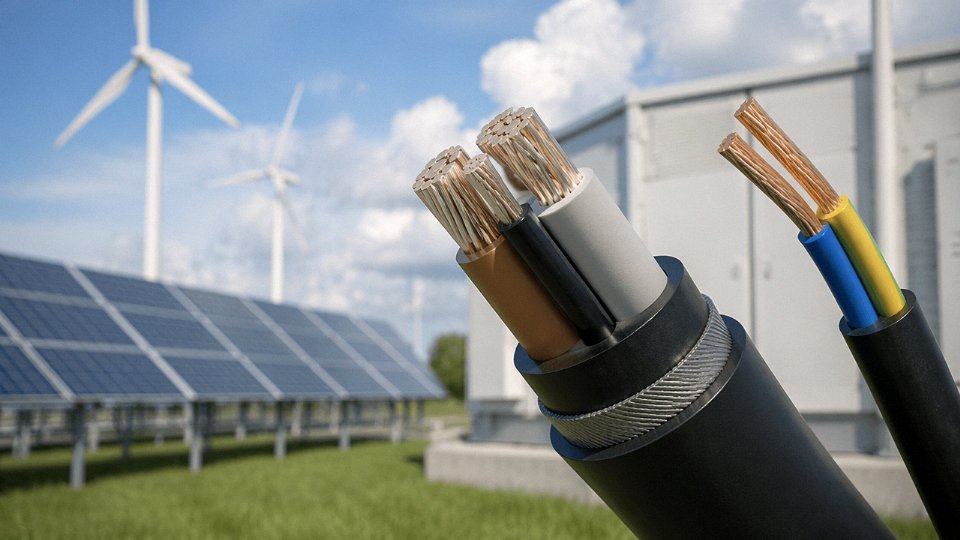
At 110 kV to 500 kV, XLPE-insulated cables with corrugated aluminium or steel wire armour are the standard choice for underground transmission corridors. At these voltages, the dielectric integrity of the XLPE is the whole game — joint quality and installation bending radius matter as much as the cable itself. Offshore wind farm export connections add a layer of complexity: submarine cables require a lead or aluminium moisture barrier over the XLPE, then single-wire armour (SWA or double SWA on deep-water routes) and an outer PP or HDPE serving. These cables run to 220 kV and beyond on major offshore projects, and the procurement lead time alone — typically 18 to 36 months for large submarine sections — means early specification is not optional.
Urban Distribution Networks
Underground ring-main units in cities typically run on 3-core or 4-core armoured XLPE cables at 11 kV or 33 kV. The armouring (usually SWA for trefoil-laid single-core, or AWA for three-core) provides mechanical protection in congested duct routes. LV service cables — 0.6/1 kV, 4-core, from distribution transformers to metering points — are almost universally XLPE or PVC insulated with DSTA or SWA depending on the utility’s standard. Pull tension limits during installation are worth checking; oversized duct bends are a regular cause of insulation damage on these relatively affordable cables that nobody notices until the fault.
Building and Construction
NYM-style cables (H05VV-F or H07VV-F in European nomenclature) cover most fixed residential wiring. In public buildings, tunnels, and hospitals, LSZH (low smoke zero halogen) compound is mandated by local fire codes in most jurisdictions — not a preference, a legal requirement. The practical reason: PVC insulation burning in an enclosed corridor generates hydrogen chloride gas that incapacitates occupants before the fire itself does. Single-core wire pulled through conduit remains common for branch circuit wiring in commercial fit-outs, particularly where future rewiring flexibility matters.
Heavy Industry and Mining
Mining trailing and reeling cables are built for punishment — extra-tough rubber or EPR sheath, flexible copper stranding, and often a steel wire mesh screen for mechanical protection. EPR insulation is also the right call in petrochemical plants: it maintains flexibility down to around -40 °C (useful in northern installations) and resists oil and hydrocarbon contamination better than XLPE in wet, chemical-laden environments.
Marine, Offshore, Data Centers, and EV Infrastructure
Vessels and offshore platforms need halogen-free, mud-resistant cables to the IEC 60092 series for general wiring, and fire-resistant cables to IEC 60331 for essential services — navigation, fire pumps, emergency lighting. In data centers, busbar trunking is increasingly paired with LV power cables for high-density distribution; trunking handles the horizontal backbone loads while cables serve individual rack drops and UPS feeds. EV charging cables are increasingly demanding: DC fast-chargers at 150 kW to 350 kW require combined conductors rated to 500 A DC or higher, with liquid-cooled cable assemblies now appearing on ultra-fast installations where thermal limits of passive cable would otherwise force larger, heavier cross-sections.
DC solar cable rated to EN 50618/IEC 62930 is specifically required — not just recommended — for exposed DC string wiring in photovoltaic installations, because standard flexible wire lacks the voltage rating, UV resistance, and long-term thermal stability needed for outdoor DC service life.True
EN 50618 and its successor IEC 62930 define the construction, test, and marking requirements for photovoltaic cables precisely because general-purpose wiring cables fail the UV exposure, 1.8 kV DC rating, and 30-year service life tests that PV system warranties depend on. Most installation codes and inverter warranties explicitly require compliant cable on DC strings.
Key Selection Parameters: A Practical Checklist for Engineers Choosing Between Wire and Cable
Getting the selection right before procurement saves money. Getting it wrong costs you downtime, failed inspections, and in worst cases, a fire investigation. Work through these steps in order — skipping voltage class and going straight to conductor size is the single most common mistake I see on mixed-voltage plant projects.
Step 1 — Determine System Voltage First
This is non-negotiable. If the circuit operates above 1 kV, you need a power cable with a rated voltage designation matching or exceeding your system voltage — a U₀/U of 3.6/6 kV, 6/10 kV, 8.7/15 kV, and so on up through 500 kV for EHV transmission. Single insulated wire — regardless of how thick its PVC sleeve looks — is not acceptable above 1 kV under IEC 60228, NEC, or any other recognized standard. No amount of creative conduit arrangement changes that. Start here and the rest of the selection follows logically.
Step 2 — Calculate Design Current with All Correction Factors Applied
Conductor cross-section is not something you eyeball from a table without corrections. Use IEC 60287 for cables in ground or free air. Soil thermal resistivity alone can swing your ampacity by 20–35%, depending on whether you’re in dry sandy soil (roughly 2.0–2.5 K·m/W) or moist clay near a water table (closer to 0.7–1.0 K·m/W). Stack on top of that an ambient temperature correction — a 35 °C ambient in a Middle Eastern cable trench is not the same as 20 °C in a North European basement — and a grouping factor if you’re laying multiple cables in the same trench or tray. Skipping grouping correction is probably responsible for more premature cable failures than any other single error.
Step 3 — Assess the Mechanical Environment
Direct burial without armoring is asking for trouble. Steel wire armour (SWA) or aluminium wire armour (AWA) is standard for direct-buried medium-voltage cables; in areas with documented rodent pressure — common in agricultural sites and some Asian industrial parks — galvanized SWA or corrugated steel tape armour gives noticeably better resistance than aluminium. Outdoor above-ground runs need UV-stable outer sheath; carbon-black-loaded HDPE is the reliable standard, not standard black PVC which can chalk and crack within five to seven years under direct sun in tropical climates. For flexible connections to moving machinery — press arms, conveyor drives, rolling-mill equipment — you need Class 5 or Class 6 stranded conductors with an elastomeric sheath (EPR or EI rubber). Using a rigid Class 2 stranded cable here will work fine until it doesn’t, usually at an inconvenient angle in the flex cycle.
Step 4 — Evaluate Chemical and Thermal Exposure
Oil is a killer for standard PVC sheaths. Petrochemical plants, hydraulic press areas, and transformer bays all need oil-resistant sheathing — polychloroprene (PCP), chlorosulfonated polyethylene (CSP), or a suitably compounded PE. Above 90 °C continuous operating temperature, switch to silicone rubber or PTFE insulation; XLPE tops out at 90 °C under IEC 60502 ratings and 105 °C under some UL specifications. Verify the actual temperature before specifying.
Step 5 — Check Fire and Smoke Performance
EU projects fall under the Construction Products Regulation (CPR); Eca is a minimum for most fixed wiring, Cca or B2ca for escape routes and high-occupancy spaces. Tunnels and metro rail systems typically mandate IEC 60332-3 Category C flame propagation, IEC 61034 smoke density above 60% light transmittance, and IEC 60754 halogen-free gas emission. Specifying a standard PVC cable on a metro contract will fail inspection.
IEC 61034 requires a minimum light transmittance of 60% during the smoke density test for low-smoke cables.True
IEC 61034-2 specifies that the minimum light transmittance measured during the smoke emission test shall not be less than 60%, which is the standard benchmark used for LSZH/LSOH cable qualification.
Step 6 — Verify Fault Level and Earthing Capacity
The metallic screen or armour on a medium-voltage cable must carry the prospective earth fault current for the fault clearance time your protection relay is set to — typically 0.5 to 3 seconds depending on the protection scheme. Run the adiabatic calculation per IEC 60909. If the armour cross-section comes up undersized, either upsize the armour or add a separate protective earth conductor in the trench. This step is skipped constantly on small industrial projects and comes back as a burnt screen on the first real fault.
Step 7 — Think in Lifecycle Cost, Not Unit Price
XLPE-insulated cables correctly installed and terminated are designed for 30–40 years of service life. A PVC cable specified to save cost in an application that genuinely needs XLPE — high ambient temperature, thermal cycling, wet soil — will likely need replacement in 12–18 years, sometimes sooner. Add installation labour, civil costs for a direct-buried run, and production downtime during replacement, and the “cheaper” cable costs two to four times more over the asset life. The right cable selected once is almost always the economical choice.
Installation, Testing, and Commissioning Requirements That Differ Between Wires and Power Cables
The gap between wire and cable doesn’t close at the point of purchase. It follows you onto the job site, into the test bay, and through the asset’s entire service life. Getting these requirements wrong is where real money gets lost — a cable pulled too hard through a duct, a termination made without stress control, a VLF test skipped because the crew assumed DC was fine. Each of those is a failure waiting to happen.
Bending Radius: More Constraining Than Most Site Teams Expect
LV armored power cables — your typical SWA or DSTA multicore — need a minimum installation bend radius of roughly 12 to 15 times the overall cable diameter. Go tighter and you risk cracking the XLPE insulation or deforming the armor wires, neither of which is immediately visible. MV cables are worse: 15 to 20 times diameter is the working rule, depending on construction and manufacturer specification. In practice, this matters most at duct entry points and cable tray corners where a rushed installation crew is trying to make a short run fit. Individual hookup wires in conduit are far more forgiving — 5 to 8 times conductor diameter is typical — which is why wire installation is generally straightforward and cable routing requires actual planning.
Pulling Tension and Side-Wall Bearing Pressure
For copper conductors, the accepted maximum pulling tension is around 50 N/mm² of conductor cross-section; for aluminum, roughly 30 N/mm². A 240 mm² copper cable can theoretically take about 12 kN of pulling force before conductor stretching becomes a concern — but that’s a ceiling, not a target. Side-wall bearing pressure at bends is often the binding constraint before tension even becomes an issue. Exceed it and you can crush the insulation against the conduit wall without any visible sign until the cable fails under load months later. Wires pulled through panels or bundled in looms face none of this engineering overhead.
Jointing and Termination: Not a DIY Operation for Power Cables
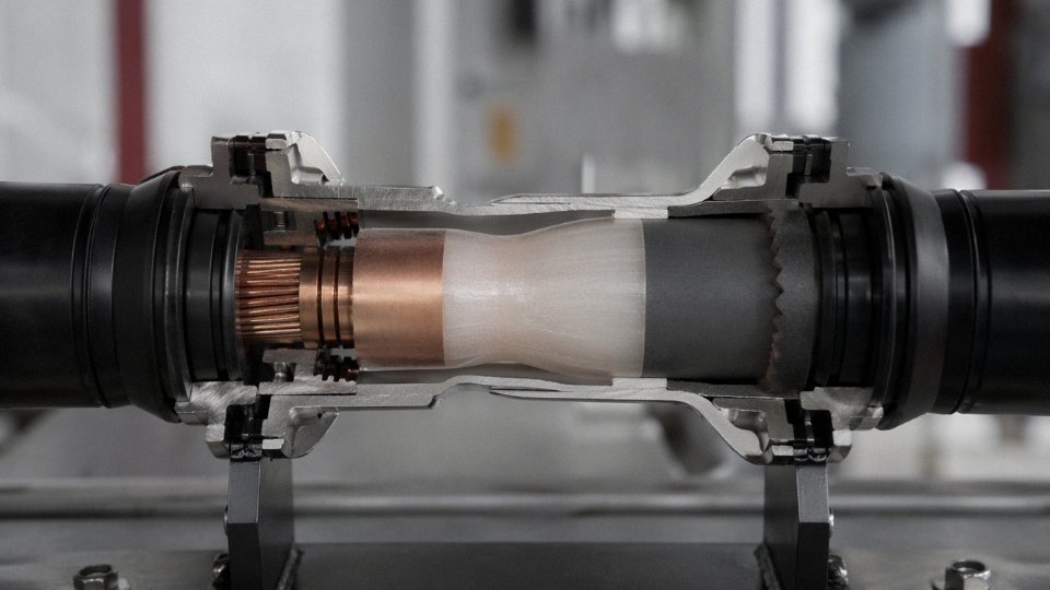
Wire terminations are simple — a correctly sized crimp lug or a torqued screw terminal, done in a few minutes by any competent electrician. Power cable terminations at MV and above are a different discipline entirely. The insulation cut-back creates a point of intense electric field stress, and without a proper stress cone — whether heat-shrink, cold-shrink, or pre-molded — that stress concentrates and eventually causes insulation breakdown. Certified jointers, correct kit, and manufacturer-specified installation procedures are non-negotiable. A pre-molded straight joint on a 33 kV XLPE cable takes a skilled team several hours to complete correctly. Rushing it is how cables that should last 40 years fail in four.
Pre-Commissioning Electrical Tests
For power cables, DC high-voltage withstand testing has largely given way to AC VLF (very low frequency, 0.1 Hz) testing per IEC 60060-3, particularly for XLPE-insulated cables — DC testing can cause space charge accumulation in XLPE that actually damages good cable. Insulation resistance measurement, partial discharge testing for MV and HV cables, and continuity plus phase identification checks are all part of a proper pre-commissioning routine. For wires in panels and assemblies, a Hi-Pot test per UL or the relevant IEC standard, a continuity check, and a spot insulation resistance check are usually sufficient — faster, simpler, and requiring no specialist equipment.
Earthing of Screens and Armor
LV multicore cable armor gets earthed at both ends as routine. Single-core HV cables are different: bonding both ends creates a closed circuit that allows circulating currents in the sheath, which can be significant at high load — potentially 20–40% of conductor current in a poorly bonded system, depending on cable length and current magnitude. Single-point bonding, both-ends bonding with impedance control, or cross-bonding schemes are each appropriate under different conditions. This is an engineering decision, not a site-team call.
Ongoing Condition Monitoring
Critical power cable circuits warrant periodic tan-delta (dissipation factor) testing and, increasingly, online partial discharge monitoring — both can detect insulation degradation years before a failure occurs. Thermal imaging of cable joints and terminations during load is also worth doing annually on high-utilization circuits. Wires in control panels and switchgear need far less: a visual inspection for chafing or discoloration, and a torque check on terminations, which tend to loosen over thermal cycling. Simple, but it gets skipped more often than it should.
VLF AC testing at 0.1 Hz is now the preferred method for commissioning XLPE power cables because DC testing can induce space charge that damages the insulationTrue
IEC 60060-3 and industry guidance from organizations such as IEEE have documented space charge accumulation in XLPE under DC test voltage, which can cause premature insulation failure. VLF testing avoids this mechanism while still revealing installation defects.
Frequently Asked Questions About Power Cable and Wire Differences
Can I use a single insulated wire instead of a rated power cable for a 10 kV feeder?
No. Full stop. IEC 60502-2 mandates a specific multi-layer construction for medium-voltage service: conductor screen, XLPE insulation at a defined minimum thickness (3.4 mm for the 8.7/15 kV voltage class), insulation screen, metallic screen, and an outer sheath. A single insulated wire has none of those layers. At 10 kV, the electric field stress at any surface irregularity on bare insulation will initiate partial discharge almost immediately — in practice, failure occurs within hours or days, not years. The consequences are not just equipment damage; an uncontrolled MV fault in a switchroom or cable tray is a serious fire and personnel safety event.
What is the difference between a cable and a cord?
A cord — H05VV-F being the classic European example — is a flexible, multi-conductor assembly specifically engineered for repeated bending and connection to portable or semi-portable equipment. The conductors are finely stranded for flexibility, and the jacket compound is chosen to handle flexing without cracking. A power cable is designed for fixed installation; it is not meant to move after commissioning. Both are multi-conductor assemblies, which is precisely what distinguishes them from a single wire. People conflate cord and cable constantly in purchasing conversations, and it rarely causes catastrophic problems at low voltage — but specifying a cord for a fixed conduit installation is a waste of money, and specifying a stiff fixed-installation cable for a machine tool’s trailing connection will cause premature conductor fatigue failure, usually at the entry gland.
Why does a power cable cost so much more than a wire of the same conductor size?
Because the copper or aluminum conductor is only part of what you’re buying. For a typical MV cable, raw conductor material represents roughly 40–60% of total cost, depending on cable voltage class and current copper or aluminum spot prices. The remainder covers primary insulation 2–6 mm thick, semi-conductive screens, metallic shielding tape or copper wire screen, fillers, armour (steel wire or tape), and outer sheath compound — plus multi-stage triple extrusion, stranding, spark testing, and final high-voltage test before the drum ships. Skipping any layer is not a cost optimization; it’s a product that doesn’t meet standard.
Does XLPE cable last longer than PVC cable?
Generally yes, given equivalent installation conditions. XLPE carries a rated maximum continuous conductor temperature of 90°C versus 70°C for PVC, a short-circuit rating of 250°C against 160°C, and meaningfully lower dielectric losses at MV and above. It also resists moisture ingress and chemical degradation better over time. Design life for XLPE in normal service runs 30–40 years; PVC in comparable conditions is typically quoted at 20–25 years. That said, XLPE is not automatically the right choice — in some light industrial LV applications where temperature and voltage stress are low, PVC armoured cable is perfectly adequate and costs less. The design life advantage only matters if the other application parameters actually stress the insulation.
What does the voltage designation 0.6/1 kV on a cable mean?
The first number (0.6 kV) is the rated phase-to-earth voltage — between any conductor and the earthed metallic screen, armour, or ground. The second (1 kV) is the rated phase-to-phase voltage between any two live conductors. The insulation system is designed, dimensioned, and factory-tested against both values. Specifying a 0.6/1 kV cable on a system with a different earthing arrangement or a higher phase-to-earth voltage than 0.6 kV is a design error, not a conservative choice.
A 0.6/1 kV cable can be safely applied on any system where the phase-to-phase voltage does not exceed 1 kV, regardless of earthing arrangement.False
Earthing arrangement directly affects the phase-to-earth voltage stress on the insulation. On an unearthed or high-impedance earthed system, a single-phase fault can raise healthy-phase voltage to full phase-to-phase voltage. IEC 60502-1 defines three categories of earthing system (categories A, B, and C) with different cable voltage class requirements for the same nominal system voltage.
How do I verify that a cable drum from a supplier meets the stated IEC standard?
Request the factory test report showing conductor DC resistance per IEC 60228, insulation resistance, applied voltage test results, and dimensional measurements — all tied to the specific drum number. Cross-check the drum print legend: cable type designation, voltage rating, standard reference, conductor size, and length should all match your purchase order exactly. For high-value projects — substation feeders, renewable energy collections, offshore work — request third-party witnessed factory acceptance tests or pull independent samples for an accredited laboratory. Reputable manufacturers will not object to this. Ones who do should be noted.
What is LSZH cable and when is it required?
LSZH — low-smoke zero-halogen — cables use specially formulated insulation and sheath compounds that, when burned, produce minimal smoke opacity and release no halogen acids (chlorine, fluorine, bromine). Standard PVC produces hydrogen chloride gas when burning; in an enclosed space that gas is toxic to people and corrosive to electronics. LSZH is typically specified — and in many markets legally mandated — for tunnels, metro and rail installations, airport terminals, hospitals, offshore platforms, and data centers. The performance is tested to IEC 60754 (halogen content), IEC 61034 (smoke density), and IEC 60332 (flame propagation). It costs more than PVC; the premium varies by cross-section and sheath wall thickness but is usually in the range of 15–35% for LV cables. In open outdoor industrial sites with good ventilation, standard PVC or HDPE sheathed cable is often perfectly appropriate and the LSZH premium buys nothing practical.
Can aluminum conductor cable replace copper to reduce cost?
Yes, and it is done routinely in distribution networks and large industrial feeders. Aluminum runs roughly 50–60% less per kilogram than copper, though that gap fluctuates with commodity markets. The trade-off is conductor cross-section: aluminum needs approximately 1.6 times the copper area to carry the same current, so the cable is physically larger and heavier, which affects conduit fill, cable tray loading, and termination hardware. Connections are the critical point — aluminum oxide forms quickly on exposed conductor surface, and that oxide layer is resistive. Every aluminum termination requires anti-oxidant compound and aluminum-rated compression lugs; mixing aluminum conductors with copper-only rated lugs or forgetting the compound is how loose, overheating joints develop over a few years of thermal cycling. Done correctly, aluminum cable is reliable and economical. The decision comes down to installed cost including conduit, tray, and termination hardware, not conductor material price alone.
How Jinda Manufactures and Supplies Power Cables and Wires for Global Projects
Specifying the right product is only half the battle. Getting it manufactured to the correct standard, on time, with documentation that satisfies your project engineer and your customs broker — that is where supplier capability separates itself quickly.
Manufacturing Scale and What It Actually Means in Practice
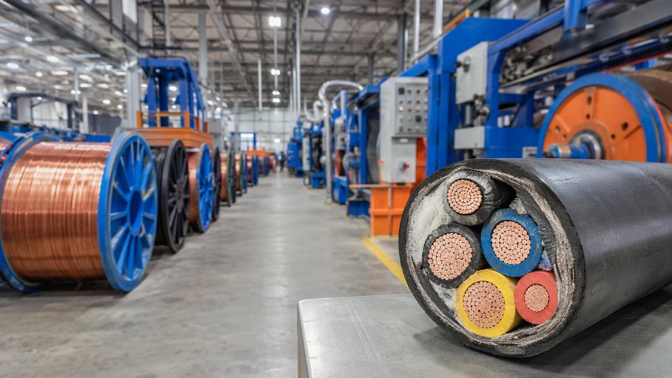
Five production bases across China, 470,000 m² of manufacturing floor space combined. Those numbers matter not because they are impressive on paper but because of what they permit operationally: parallel production runs, dedicated lines for specific product families, and the capacity to fulfill mixed orders without one product category delaying another.
The continuous vulcanization (CV) lines handle XLPE cables up to 220 kV, with production capability extending to 500 kV transmission-grade cable. CV line operation is sensitive — temperature profile, nitrogen atmosphere pressure, catenary sag control — and maintaining consistent quality at EHV ratings requires that those lines run frequently enough for operators to stay sharp, not sporadically as one-off projects. Wire drawing and stranding equipment covers conductor sizes from the fine gauges used in hookup and control wire through the large-section stranded conductors in HV cable cores. Automated extrusion handles LV and MV cable jackets and insulation at volume.
Product Range: Why Single-Source Procurement Reduces Project Risk
Jinda’s range spans bare conductors and lightly insulated hookup wire at the low end all the way through 500 kV XLPE transmission cable, with a substantial catalogue of specialized products in between: solar DC cables (TÜV and IEC 62930 rated), wind turbine cables built to withstand torsional flexing, mining trailing cables with robust outer sheaths for drag-and-crush environments, marine cables rated for salt atmosphere and limited space bundling, and fire-resistant plus LSZH building cables for critical infrastructure where smoke toxicity matters during evacuation.
For a large industrial or infrastructure project, sourcing all cable categories from a single qualified supplier eliminates the coordination overhead of managing multiple vendor quality systems, multiple FAT schedules, and — frankly — the blame-shifting that happens when two cable suppliers each claim the other product caused a compatibility issue at a joint.
Quality Systems and Certifications
Jinda holds ISO 9001 quality management certification and ISO 14001 environmental management certification, with products certified to IEC, GB, BS, and UL standards and CCC certification for the domestic China market.True
These certifications are verifiable through the respective certification bodies and are standard requirements for a manufacturer of this scale supplying regulated international markets.
For export markets specifically, type approvals cover the Middle East, Southeast Asia, Africa, Europe, and the Americas — each region tends to have its own overlay requirements beyond base IEC compliance, and having those approvals already in place avoids the 8–16 week delay of applying for a new type test mid-project.
R&D and Staying Ahead of Specification Changes
The R&D center runs ongoing programs in high-temperature superconducting cable components, HVDC cable systems, and next-generation LSZH compound formulations. LSZH compound development is less glamorous than HVDC work but arguably more immediately commercial — building codes in the Gulf, Southeast Asia, and Europe continue tightening on halogen emission limits, and a supplier whose LSZH compounds are already tested and optimized is ahead of the next specification revision rather than scrambling to catch up.
Supply Chain and Lead Time Realities
Standard lead times run roughly 15–25 days for LV cables and 30–45 days for MV cables. HV cables are project-scheduled — expect to discuss production slot allocation early, not after contract signature. Export logistics cover container shipping for standard cable drums and break-bulk for large HV reels, with established coordination through international freight forwarders.
Technical support runs from pre-sales cable sizing through FAT coordination, jointing and installation manuals, and on-site commissioning assistance for major projects. That last point — engineers available on-site — is less common than suppliers claim, and reflects the integrated service model Jinda has built since 1987.