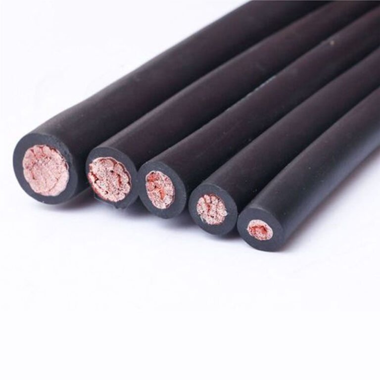
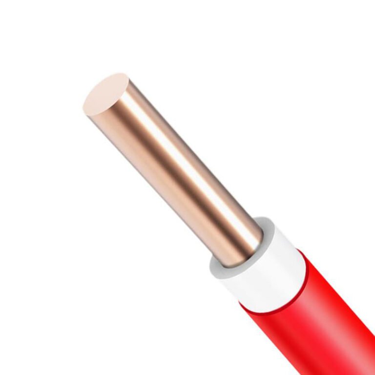
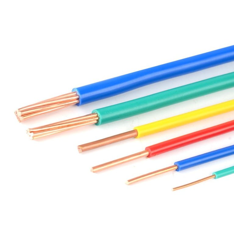
Specify “power line” when you mean “power cable” on a procurement order, and the wrong product ships — wrong insulation class, wrong installation method, potentially the wrong voltage rating entirely. That error can stall a substation build by weeks, trigger re-sourcing costs that run well into five figures, and in worst cases put a commissioning team in front of hardware that simply cannot be safely energized. The terminology sounds interchangeable in casual conversation. On a bill of materials, it is not.
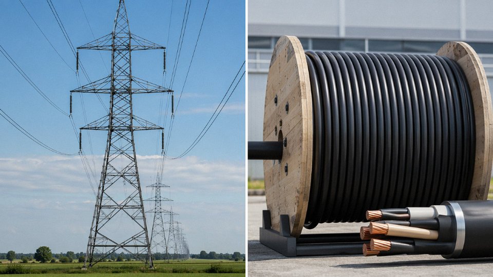
A power line is a conductor system — usually bare or lightly insulated wire strung between pylons or poles — designed to transmit electricity through open air, typically at voltages from 11 kV up to 1,100 kV on transmission networks. A power cable is a fully insulated, jacketed assembly engineered for direct burial, duct installation, or indoor routing, generally rated from 1 kV up to around 500 kV. The two differ in construction, installation environment, mechanical protection, maintenance access, and lifecycle cost.
What makes this worth unpacking in detail is that the line between the two categories has become genuinely blurry as grid modernization pushes more transmission underground, renewables demand flexible routing through constrained corridors, and procurement managers are increasingly buying across both product families inside a single project. Understanding where each technology actually lives — structurally, operationally, and commercially — is the only way to specify correctly and avoid the kind of substitution errors that cause real downtime.
Physical Construction Anatomy: What Is Actually Inside a Power Line Versus a Power Cable
Crack open a datasheet for an ACSR conductor and then pull up a spec sheet for a 132 kV XLPE underground cable. The difference in complexity is not subtle. One document lists two or three parameters. The other runs to pages of layer-by-layer requirements. That gap reflects something real about the engineering inside each product.
What a Bare Overhead Conductor Actually Consists Of
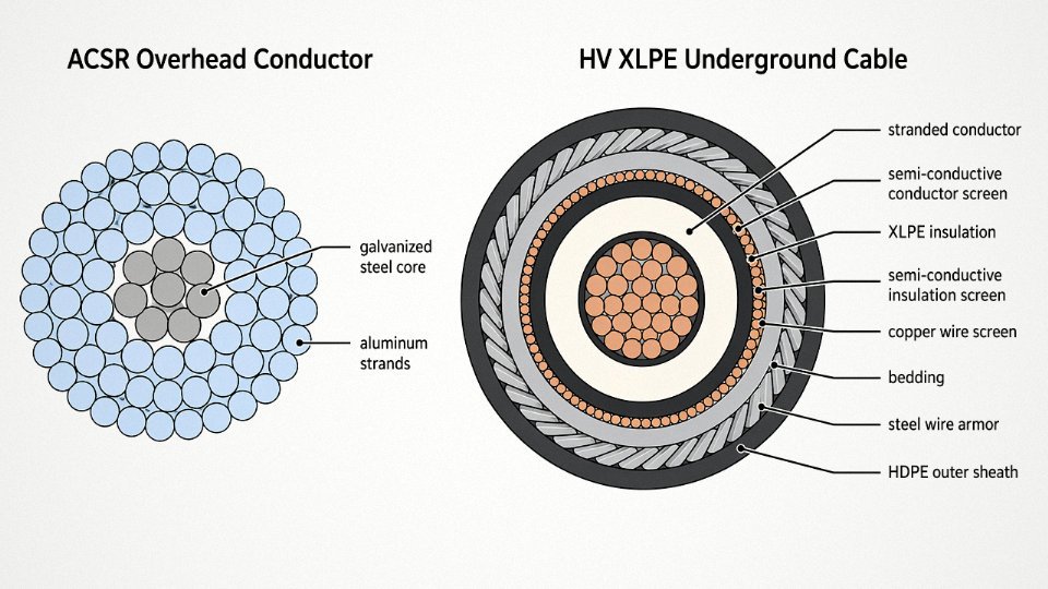
A typical ACSR (Aluminum Conductor Steel Reinforced) overhead line conductor is, structurally, quite simple: one or more layers of aluminum or aluminum alloy strands helically wound around a galvanized steel core. The steel core handles tension — in long span installations, a conductor might carry 20–30% of its rated breaking load just from its own weight and wind loading, so the mechanical and electrical functions are effectively split between materials. AAAC (All Aluminum Alloy Conductor) drops the steel core and uses higher-temper aluminum alloy to recover some tensile strength, which matters in coastal environments where the galvanized steel core corrodes faster than the aluminum outer strands. ACCC conductors use a carbon fiber composite core instead, allowing higher operating temperatures and lower sag — useful for uprating existing lines without rebuilding towers, though the cost per kilometer jumps noticeably.
Critically: there is no insulation layer. Air is the dielectric. Minimum clearances — tower geometry, phase spacing, ground clearance — do the job that a cable’s insulation stack does. This is why bare overhead lines are cheap per kilometer to manufacture but expensive in right-of-way and structurally demanding in the tower design.
IEC 61089 governs the aluminum temper and minimum conductivity for these conductors (typically ≥ 61% IACS for standard grades). Getting a supplier to confirm which edition of the standard they’re certifying to, and whether it’s third-party verified, matters more than most buyers realize.
The Layer Stack Inside a Power Cable
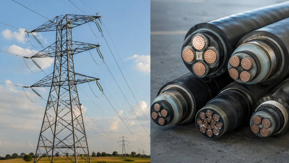
A medium-voltage or high-voltage underground cable is a different object entirely. Working from the center out, you get: the conductor (solid or stranded copper or aluminum, with class of stranding selected for flexibility requirements), then a semi-conductive conductor screen, then the main insulation, then a semi-conductive insulation screen, then a metallic screen (copper tape, copper wire, or aluminum foil depending on fault current requirements), then bedding, then armor (steel wire armor for buried direct-laid cables, often omitted in duct-laid), then the outer sheath.
Each of those layers is earning its place. The conductor screen smooths out the electric field at the conductor surface — without it, field concentration at strand interstices would degrade insulation life measurably over time, particularly above 33 kV. The XLPE main insulation handles dielectric stress; at 500 kV, that’s roughly 8–12 kV/mm depending on design, and the crosslink purity standards under IEC 60840 and IEC 62067 exist precisely because contaminants and voids at that stress level initiate treeing failures. The armor on a directly buried cable isn’t decorative: a single excavator strike or persistent rodent pressure on an unarmored sheath can cause the kind of fault that takes a substation offline for weeks.
XLPE cable insulation for voltages above 150 kV must meet the higher purity crosslinking requirements specified in IEC 62067, not just IEC 60840True
IEC 62067 covers extruded insulation power cables rated 150 kV and above (Um), imposing stricter requirements on XLPE cleanliness and testing than IEC 60840, which applies to cables from 30 kV up to 150 kV.
A Side-by-Side Layer Comparison
| Construction Layer | Bare ACSR Overhead | Covered ABC Overhead | MV XLPE Underground | HV Submarine Cable |
|---|---|---|---|---|
| Conductor material | Al strands + steel core | Al strands + steel core | Stranded Cu or Al | Stranded Cu (usually) |
| Conductor screen | None | None | Semi-conductive layer | Semi-conductive layer |
| Main insulation | None (air) | PE or XLPE covering | XLPE (3–35 kV typical) | XLPE (up to 500 kV) |
| Insulation screen | None | None | Semi-conductive layer | Semi-conductive layer |
| Metallic screen | None | None | Cu tape or wire | Cu wire or Al foil |
| Armor | None | None | SWA (if direct buried) | Wire armor (heavy) |
| Outer sheath | None | Optional PE | HDPE or PVC | PE (often HDPE) |
The ABC (Aerial Bundled Cable) entry is worth flagging: it sits between the two extremes. The conductor is still self-supporting overhead, but it carries a PE or XLPE insulation layer thick enough for 1 kV or 11 kV operation, making it suitable for distribution in areas where bare conductors would pose unacceptable contact or vegetation clearance risks. It is not a cable in the underground sense, but it is not a bare conductor either.
Why Material Grade Is Not a Minor Detail
Specifying “XLPE insulated” on a purchase order without referencing the voltage class and applicable IEC standard leaves the door open for supplied material that meets the letter of the order but not the engineering intent. Cable-grade XLPE for 66 kV and above requires controlled degassing, low ionic contamination, and documented crosslink density — none of which is visible on arrival. Similarly, overhead conductor aluminum specified without a conductivity minimum could arrive at the lower end of commercial aluminum alloy tempers, adding resistive losses that compound over decades of operation. These are procurement details that look like paperwork but show up as energy costs and premature failures on the plant floor.
Jinda’s five production bases in China manufacture across this full range — bare overhead conductors, ABC insulated overhead cables, medium-voltage XLPE underground cables, and armored underground cables — within a single integrated quality system. That vertical integration means the same IEC traceability requirements apply whether you’re ordering distribution-class ABC or a higher-voltage underground run, which is worth verifying through third-party test reports regardless of supplier.
Voltage Classes, Current Ratings, and Electrical Performance Benchmarks
Voltage class is probably the single most consequential variable when deciding between overhead line and underground cable — it affects insulation design, thermal management, fault protection strategy, and ultimately whether a given product even exists in the configuration you need.
Overhead Line Voltage Range
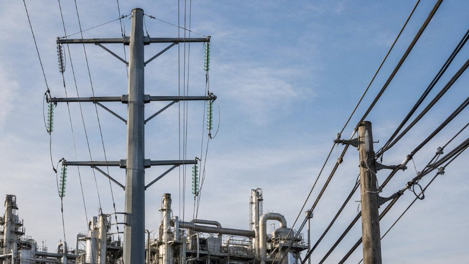
Bare overhead conductors run the full spectrum. At the low end, 230 V single-phase rural distribution lines are still common across parts of Southeast Asia, sub-Saharan Africa, and South America — simple bare aluminum or copper strung between wooden poles, essentially no dielectric complexity at all. Step up to 11 kV or 33 kV distribution and you’re still in overhead ACSR (aluminum conductor steel reinforced) territory for most utility networks, though covered conductors appear in wildfire-risk or dense-canopy zones.
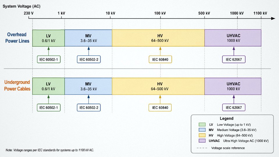
Long-distance bulk transmission is where overhead lines really dominate. The 500 kV and 750 kV AC corridors that cross North America, Europe, and large parts of Asia move gigawatts across hundreds of kilometers on lattice steel towers with bundled conductors — typically two to four sub-conductors per phase to manage corona and reduce AC resistance. China and India have pushed further still: UHVAC at 1,000 kV and UHVDC links rated 800 kV to 1,100 kV on dedicated transmission corridors, where the economics of overhead construction over open land are essentially irreplaceable. Underground cable simply cannot compete at that voltage and that scale, at least not today.
Underground Cable Voltage Classes and Relevant Standards
IEC standards give procurement teams a clean framework here. LV cables per IEC 60502-1 cover the 0.6/1 kV range — building feeders, industrial plant distribution, the bulk of what moves in container quantities. Medium voltage per IEC 60502-2 spans 3.6/6 kV up to 26/35 kV, covering most utility distribution networks that run underground in urban areas. Above that, IEC 60840 governs HV extruded cables from 64/110 kV through 290/500 kV, and IEC 62067 applies to EHV and submarine cables above 150 kV where factory qualification testing becomes genuinely demanding — routine tests on 500 kV cable joints, for instance, involve withstand voltages and partial discharge levels that require dedicated high-voltage test bays.
Current Capacity: Why Overhead Lines Win on Raw Ampacity
This is where the physics is unforgiving. A 240 mm² XLPE-insulated underground cable in direct burial (assuming standard soil thermal resistivity around 1.0 K·m/W and ambient ground temp of 20°C) will typically carry somewhere in the 430–520 A range continuously — the exact figure depends on burial depth, grouping with other cables, and whether you’re pulling through a duct or direct burying. A 240 mm² ACSR conductor on an overhead line in open air, reasonable wind and 35°C ambient, will handle roughly 600–700 A, sometimes more. The gap comes entirely from heat dissipation: open air convective cooling is far more effective than conduction through soil. This is why high-voltage overhead transmission corridors remain the preferred choice for bulk power movement wherever right-of-way is available.
A 240 mm² XLPE underground cable has lower continuous current capacity than a comparable overhead ACSR conductor of the same cross-section.True
Underground cables dissipate heat through soil conduction, which is far less efficient than convective air cooling around overhead conductors. Thermal resistivity of soil and installation configuration are the limiting factors, not the conductor itself.
Dielectric Losses and Reactive Compensation in HV Cable Runs
One issue that surprises engineers moving from overhead to underground for the first time: capacitive charging current. Above roughly 66 kV, a long AC underground cable run generates substantial reactive power — capacitance per kilometer for a 132 kV XLPE cable runs perhaps 0.15–0.25 µF/km, depending on insulation geometry. On runs beyond 30–50 km, that charging current consumes a meaningful portion of thermal capacity before you’ve moved a single watt of real load. Reactive compensation (shunt reactors at cable ends, sometimes mid-point) becomes mandatory, and that adds cost that doesn’t appear in overhead equivalents. Overhead lines at comparable voltages have roughly an order of magnitude less capacitance per kilometer, so this is rarely a design constraint.
Short-Circuit Withstand and Fault Behavior
Armored underground cables must carry a defined fault current for the relay clearance time — IEC 60949 gives the methodology. Get this wrong and you’re melting a 110 kV joint inside a congested urban tunnel, which is an expensive and slow repair. Overhead bare conductors don’t have insulation to scorch, so a thermal fault heats the conductor and protection trips; the conductor itself may anneal and sag long-term, but the failure mode is far less catastrophic than a buried cable joint failure.
Three project types illustrate how voltage class maps to product choice in practice: an offshore wind farm 220 kV submarine cable link of 50–100 km (XLPE, IEC 62067, with full factory type testing); a 110 kV underground cable tunnel replacing aging overhead line through a city center (single-core XLPE trefoil-laid, sheath bonding critical); and a rural 11 kV bare ACSR distribution network where conductor choice comes down to span length, wind loading, and ice zone — voltage is almost secondary.
Installation Environments: Where Each Technology Is Engineered to Operate
The question of overhead versus underground is rarely a free choice. Terrain, land ownership, regulatory jurisdiction, fault exposure, and thermal environment all push the decision in one direction or the other — sometimes before a single calculation is run.
Overhead Lines: Where Open Corridors Make Them Viable
Overhead lines dominate wherever right-of-way can be secured at reasonable cost and visual intrusion is not a blocking issue. Rural transmission corridors, agricultural flatlands, mountain ridgelines, and river crossings using catenary spans are the natural habitat. Span lengths between towers typically run 20–100 m for distribution structures and can extend considerably longer for high-voltage river or valley crossings — the exact figure depends on conductor sag limits, ice and wind loading zone, and tower foundation costs.
Mountain terrain introduces its own complications. Ice accretion in alpine zones can multiply mechanical load on bare conductors several times over, and wet-snow adhesion in mid-altitude temperate regions causes conductor galloping that fatigues hardware connections faster than most maintenance schedules anticipate. In those environments, the cost advantage of overhead construction erodes noticeably.
Underground Cables: Dense Infrastructure, High-Stakes Environments
Urban and suburban environments essentially mandate underground installation for anything feeding critical loads. There simply is no overhead corridor available through a city center, and even where corridor exists in theory, planning authorities in Europe, Japan, South Korea, and increasingly across Chinese municipal grids will not permit it above a certain voltage threshold. That threshold varies by jurisdiction — some European grid codes draw the line at 110 kV, others at 33 kV for urban cores — but the direction of travel is consistent: more underground, not less.
Beyond urban density, several physical environments make underground cable the only technically sound option. Airports prohibit overhead structures within approach and departure zones for obvious reasons. Protected landscapes — national parks, heritage corridors, coastal zones — carry statutory protections that block overhead infrastructure regardless of cost. Industrial plant areas almost always route medium-voltage distribution underground to protect against mechanical damage from mobile equipment, and to keep the aerial space clear for cranes and process structures.
Areas with high lightning incidence or severe ice-and-wind loading represent a different argument entirely. Overhead structures in those zones require substantial surge arrester programs, regular hardware inspection, and accept a base rate of weather-related outages. For a utility serving a load that cannot tolerate interruption, the capital premium of underground cable can be justified on reliability grounds alone.
Hybrid Solutions: Covered Conductor and Aerial Bundled Cable
Forested areas and wildfire-prone zones occupy an uncomfortable middle ground. Bare overhead conductors in these environments present real ignition risk — contact with vegetation under dry conditions, or conductor slap during high-wind events, has been a documented ignition mechanism in multiple fire seasons across Mediterranean and Pacific-rim climates. Covered conductor and aerial bundled cable (ABC) address this without requiring the full cost of underground installation. The partial insulation on ABC suppresses contact arcing while the aerial installation method preserves relatively straightforward maintenance access. Jinda produces ABC cables to IEC 61089 and to customer-specified national standards where local grid operators mandate particular constructions.
Soil Thermal Conditions: The Underground Variable Most Often Underestimated
An underground cable’s continuous current rating is controlled almost as much by what surrounds it as by what is inside it. Native soil thermal resistivity typically ranges from about 0.7 K·m/W in moist sandy soils up to roughly 2.5 K·m/W in dry clay or crushed rock — a range that can derate a cable’s ampacity by 30–40% on the unfavorable end if no corrective action is taken. Specifying fluidized thermal backfill (thermal resistivity around 0.5 K·m/W) around the cable bedding zone is standard practice on HV installations and is not optional if the design is to hold.
Burial depth follows voltage class. Medium-voltage cables typically sit at 0.8–1.2 m, high-voltage circuits at 1.0–1.5 m, though local grid operator standards override these defaults. Proximity to district heating pipes, other power cables, or steam lines must be assessed at the route survey stage; a cable routed too close to a heat source in a congested urban duct bank can run well above its design temperature continuously, shortening insulation life in ways that won’t surface for years.
Thermal backfill specification can improve underground cable ampacity by 20–35% compared to native soil placement in poor thermal soil conditions.True
This range is consistent with IEC 60287 ampacity calculation methodology, which directly accounts for thermal resistivity of the surrounding medium; the improvement depends on native soil resistivity and cable geometry.
Submarine and Offshore Environments
Submarine routes introduce mechanical and corrosion demands that land cable construction simply is not designed for. A cable serving a fixed seabed route uses rigid steel wire armor and typically incorporates a lead or corrugated aluminum sheath for saline corrosion protection. Floating offshore wind turbines require something different — dynamic cables built with flexible armor systems that tolerate continuous bending as the platform moves, with fatigue life calculated across the service life of the turbine itself, often 25 years in an aggressive marine environment. Bend radius restrictions during the lay operation are not a theoretical footnote; violating them during installation has caused armor wire damage that was only discovered during commissioning testing. Getting the cable-lay vessel and the cable specification aligned before contract award is the kind of thing that sounds obvious but causes real problems when procurement and marine operations teams are working on separate timelines.
International Standards Governing Power Lines and Power Cables: IEC, IEEE, and National Codes
If you’re sourcing conductors or cable for an export project and you get the standard wrong, you don’t just fail an inspection — you can hold up an entire grid interconnection, trigger re-testing at your cost, or watch a utility reject a full shipment at port. Standards aren’t bureaucratic noise. They define what tests a product must survive, how it’s rated, and ultimately whether an EPC contractor or national utility will accept it.
IEC Standards for Overhead Conductors
The core document for bare overhead conductors is IEC 61089, which specifies round wire concentric lay stranded conductors — ACSR, AAC, AAAC, and ACAR types. It covers conductor geometry, tensile strength, and resistivity limits. When a buyer asks for “ACSR to IEC,” this is the standard they mean. Mechanical performance of the line as a whole — wind and ice loading, sag-tension calculations, security levels — falls under IEC 60826, which is what structural engineers use when designing towers and poles for a specific climate zone. Fittings (clamps, suspension sets, tension clamps) are governed by IEC 61284, and composite insulators by IEC 61466. These four standards together cover the entire overhead system, not just the conductor itself. Specifying IEC 61089 conductor and then using non-compliant fittings is an error that shows up as hardware failure under load, not on paper.
IEC Standards for Power Cables
The cable side has a more layered structure. IEC 60228 defines conductor classes — class 1 (solid), class 2 (stranded), class 5 and 6 (flexible) — and governs resistance values per cross-section. Every cable standard references it. For LV and MV extruded cables, IEC 60502-1 (up to 1 kV) and IEC 60502-2 (1–30 kV) are the workhorse documents; most distribution cable projects globally specify these two. Above that, IEC 60840 covers HV cables from 30 to 150 kV, and IEC 62067 handles EHV cables above 150 kV — XLPE transmission cables destined for major grid interconnections or offshore wind export circuits.
Current rating methodology is separate from construction standards. IEC 60287 is the calculation framework engineers use to determine how much current a cable can carry in a specific installation — buried depth, soil thermal resistivity, grouping factor all feed into it. Get those inputs wrong and you’re either under-utilizing an expensive cable or cooking the insulation within a few years. IEC 60332 addresses flame retardance and covers a range of test severities; for tunnels and public buildings, the specific test tier matters.
IEEE and North American Requirements
North American projects run on a different document set. IEEE 1283 covers ACSR conductor characteristics. For underground cable, ICEA S-94-649 (MV, 5–46 kV) and ICEA S-97-682 (HV, 69–500 kV) are the dominant specifications, often called out alongside IEEE standards in utility specs. Overhead clearances and safety rules are set by the NESC — the National Electrical Safety Code — which dictates minimum heights, worker safety distances, and loading districts. A cable that passes IEC testing does not automatically satisfy ICEA requirements; some dimensional and test differences are real enough to require separate qualification.
National and Regional Certification
Jinda certifies product against GB/T (Chinese national standards), BS (British), and DIN (German) standards, and routinely supplies to AS/NZS requirements for Australian and New Zealand projects. Middle East, African, and Southeast Asian grid projects frequently come with customer-specific project specifications layered on top of IEC — sometimes tighter, sometimes just different in test sequence. The practical answer is to confirm the exact document revision before production starts, not after.
Type Testing, Routine Testing, and the Gap Between Them
This distinction trips up a lot of procurement teams. A type test is a one-time qualification test on a cable design — it includes partial discharge measurement, high-voltage impulse withstand, bending tests on full-length samples, and heat cycle tests. For HV and EHV cable, IEC 60840 and IEC 62067 specify exactly what that sequence looks like. Once a design passes type testing, routine tests (conductor resistance, voltage test, insulation resistance) are performed on every production length. A supplier offering HV cable without valid type test reports is a serious red flag.
Overhead conductors follow a different path. IEC 61089 requires tensile breaking load tests, creep tests under sustained stress, and conductivity verification. These are typically done on production samples, and major buyers specify which accredited lab must witness them.
IEC type test reports for HV cables are valid indefinitely as long as the cable design does not changeFalse
IEC 60840 and IEC 62067 require that type test reports remain representative of current production; significant design changes — such as insulation compound, conductor cross-section, or screen design — require re-qualification. Most major utilities also set an expiry window, commonly 5–10 years, after which they request updated testing.
Third-Party Audits and Witness Testing
Major utility buyers and EPC contractors rarely rely on self-declared conformity for transmission-class product. They send auditors. The standard expectation is ISO 9001 quality management certification at minimum, and ISO 14001 environmental management for public-sector and European buyers. Independent witness testing at labs like KEMA (Netherlands), CESI (Italy), or CPRI (India) is commonly required for HV and EHV cable qualification. Jinda’s five production bases operate under a unified quality system designed to support exactly this kind of third-party scrutiny — factory audits, witnessed production tests, and full traceability documentation — which matters when a project owner’s engineer shows up unannounced before shipment.
Total Lifecycle Cost Comparison: Capital Expenditure, Maintenance, Losses, and End-of-Life
Upfront price is the wrong place to stop the analysis. In my experience, the technology choice that looks cheaper on a capital budget often reverses position once you fold in twenty years of maintenance, storm repair, and energy losses. Here is how the numbers actually stack up.
Capital Expenditure: Overhead Lines
For a 110–230 kV overhead transmission line, total installed cost typically falls between $285,000 and $1,000,000 per mile. That range is wide because the drivers are highly site-specific. Conductor material — usually aluminum conductor steel-reinforced (ACSR) or all-aluminum alloy conductor (AAAC) — tracks commodity markets closely; aluminum currently prices somewhere around $2,000–$2,800 per tonne depending on LME spot and order volume, and conductor weight per kilometer varies with cross-section, so a 400 mm² ACSR line costs meaningfully more in material than a 185 mm² line even before you touch the structure cost.
Tower structures (lattice steel at transmission voltages, concrete or spun poles at sub-transmission) typically represent 30–40% of installed cost on flat terrain, but that share climbs sharply in mountainous or heavily forested corridors where access roads and helicopter stringing add labor days fast. Insulator strings, earthing conductors, and surge arresters are relatively modest line items individually. Right-of-way acquisition is the wild card — in dense agricultural or peri-urban land it can rival the conductor and structure cost combined.
Capital Expenditure: Underground Cables
Underground cable projects run $500,000 to $3,000,000 per mile, and the spread is if anything wider than for overhead lines. Civil works — open-cut trenching, duct installation, backfill, and surface reinstatement — typically account for 50–70% of installed cost in urban settings. In rock or under roads, horizontal directional drilling (HDD) pushes costs toward the upper end fast. The cable itself carries more conductor metal per kilometer than the equivalent overhead line (underground ratings often require larger cross-sections to manage thermal dissipation in soil), and high-voltage XLPE cables use copper or large-section aluminum with extruded insulation, metallic screens, and armoring that simply cost more per meter than a bare overhead conductor.
Cable joints every 300–500 m add up: each factory joint or field joint at 132 kV and above involves skilled jointers, specialized tooling, and hours of work. Terminations at each end are similarly expensive. This is a line item that sometimes gets underestimated at the procurement stage.
Operational and Maintenance Costs
Overhead lines are not “fit and forget.” Annual costs for patrol inspections, vegetation management (one of the most persistent budget items), insulator washing in polluted corridors, and emergency storm repair typically run $5,000–$25,000 per km per year — the higher end applies to lines in heavily treed terrain or regions with severe ice or wind seasons. A single ice storm event on an exposed 50 km line can consume several years of routine maintenance budget in one outage.
Underground cables, by contrast, need minimal routine attention once installed correctly. The risk profile is just different: faults are rare but when they happen, locating the fault and excavating for repair takes days rather than hours. Joint failure is the dominant failure mode, and a single joint replacement at high voltage is not a quick job.
Energy Losses
XLPE insulated cables generally show lower resistive losses at equivalent conductor cross-sections compared to overhead lines, partly because bundled overhead conductors experience proximity and skin-effect losses that single-core underground cables avoid. At extra-high voltage, overhead lines lose measurable energy to corona discharge, which is why EHV lines use bundle conductors to reduce surface gradient. Underground cables at high voltage introduce dielectric losses in the XLPE insulation — usually minor at 66–132 kV but worth accounting for at 400 kV and above.
IEEE and CIGRE statistics show underground cables experience roughly 0.05–0.1 faults per 100 km per year, compared to 0.5–2.0 faults per 100 km per year for overhead lines in comparable voltage classes.True
This fault rate differential is well-documented in CIGRE technical brochures and IEEE PES reliability surveys, though actual rates vary by region, weather exposure, vegetation management practices, and asset age.
Fewer faults sounds like a clear win for cables, but repair duration closes the gap. An overhead line fault in accessible terrain is often cleared in hours; an underground fault can take two to five days from fault location through excavation to jointing and reinstatement. Net reliability impact is genuinely project-specific — a dense urban network where any outage has massive consequence value will still favor underground, while a rural feeder in flat terrain may not justify the cost premium.
Asset Life and End-of-Life Recovery
Overhead bare conductors are typically designed for 40–50 year service life, with periodic re-tensioning and hardware replacement extending that in practice. XLPE underground cables carry manufacturer warranties in the 30–40 year range, which depends heavily on correct installation — soil thermal resistivity, laying depth, backfill quality, and joint workmanship all affect actual life. End-of-life copper and aluminum recovery from cables is a real offset: a cable with 630 mm² copper conductors contains substantial scrap value per kilometer that partially funds replacement. For procurement managers building a 30-year asset model, that scrap recovery line belongs in the spreadsheet.
Selecting the Right Solution: A Decision Framework for Engineers and Procurement Teams
By the time you’ve worked through construction anatomy, voltage classes, and lifecycle costs, the real question becomes: how do you actually make the call on a live project? Here’s a structured sequence that reflects how experienced engineers work through it — not a theoretical checklist, but the order in which each step genuinely constrains the next.
Step 1 — Define the Electrical Requirements First
Start with system voltage, maximum continuous load current, and fault level. These three numbers immediately eliminate whole product categories. A 33 kV rural feeder and a 400 kV transmission link are not a “which is cheaper” comparison — they’re different engineering worlds. Also determine AC or DC early; HVDC cable systems require extruded or mass-impregnated insulation rated for polarity reversal stress, and sourcing those on a short timeline is genuinely difficult.
Fault level matters more than many junior engineers realize. Specifying a cable with a 16 mm² copper screen when your network fault level demands withstand for 20 kA for one second will get you a failed screen — and a very expensive incident.
Step 2 — Walk the Corridor Before Opening a Catalogue
This step makes the decision automatically in more cases than you’d expect. Map your route for right-of-way availability, land-use zoning (agricultural, urban, flood plain, airport approach zones), terrain difficulty, and soil conditions. In urban corridors, overhead lines are often simply not permitted — the decision is already made. In rocky highland terrain, direct-burial cable trenching cost can push the economics back toward overhead. Flood-prone routes favor underground with suitable bedding and protection. Seismic zones above Intensity VIII (Chinese standard) or Zone 4 (IBC) introduce specific burial depth and flexible joint requirements that need to be designed in, not bolted on afterward.
Soil thermal resistivity is frequently overlooked. The difference between dry sandy soil (around 2.5–3.0 K·m/W) and moist clay (0.8–1.2 K·m/W) can shift your cable’s continuous current rating by 15–20%, which in practice means the next conductor cross-section size up — and a meaningfully different price per kilometer.
Step 3 — Regulatory and Grid Code Requirements
Before any final specification, obtain the local utility’s interconnection technical requirements and any environmental permitting conditions. Grid codes vary enough between jurisdictions that what passes in one country requires a change order in another. This is especially true for export projects; buyers in Southeast Asia, the Middle East, and Sub-Saharan Africa often face overlapping national grid codes and legacy IEC/IEEE hybrid requirements that need explicit reconciliation in the procurement spec.
Step 4 — Reactive Compensation on Long Underground AC Routes
Underground AC cables generate substantial charging current. Runs beyond roughly 30 km at 110 kV, or 15 km at 220 kV, will typically require mid-point shunt reactors to manage reactive power — sometimes more than one, depending on load profile and network configuration. These reactors are not cheap, and they occupy real estate. If your financial model for the underground option doesn’t include them, your cost comparison is wrong.
Step 5 — Prepare a Proper Bill of Materials
Vague specifications cost money. State conductor cross-section, insulation voltage class, armor type (wire or tape, steel or aluminum), outer sheath color, drum length, and required third-party test certificates. Drum length is the one engineers routinely omit — and then regret. For a long HV route, forcing unnecessary joints because drums were too short adds jointing labor, joint kits, and — more importantly — additional points of potential failure.
HV cable drum weights can reach up to 20 tonnes for transmission-class products, requiring specialized transport and crane handling at the installation site.True
Transmission-class cables at 110 kV and above with large conductor cross-sections and heavy armor on full-length drums routinely reach 15–20 tonnes, which determines transport route planning, crane specifications, and laydown area requirements at the project site.
Jinda’s technical team provides IEC-compliant datasheets and factory test reports across all product lines — useful when a client or local utility requires documentation before approving a foreign-sourced product.
Step 6 — Verify Supplier Capability Against Project Scale
For bulk infrastructure projects, production capacity and lead time matter as much as unit price. Ask specifically: what is the factory’s monthly output for this voltage class? Can they meet your cable drum logistics requirements? Do they offer on-site technical support or jointing supervision, or does that fall entirely on your installation contractor?
Common Specification Mistakes Worth Avoiding
Under-specifying armor for direct burial in rocky soil is probably the most common field problem — standard round wire armor gets damaged during pull-in through conduit in stony ground, and flat wire armor or double-layer protection should have been specified. Neglecting screen cross-section for fault current withstand is the second. Selecting conductor cross-section based purely on continuous current rating without checking voltage drop over long rural LV runs is a persistent error on agricultural electrification projects, where a line might be thermally fine but delivering 180 V at the far end.
Work through these steps in sequence, and the “line vs. cable” question usually answers itself before you reach the pricing stage.
Frequently Asked Questions About Power Lines and Power Cables
Can a power cable be used above ground instead of an overhead line?
Technically, yes — but only with the right product. Standard underground XLPE or PVC-insulated cables are not engineered for continuous UV exposure, the thermal cycling that comes with direct sun on an unburied run, or the wind-induced vibration that builds fatigue cracks in conductor strands over years. Put an underground cable on a surface tray in an outdoor yard and you might get away with it for a season; run it that way for a decade and you’ll be dealing with sheath embrittlement and insulation degradation well before the design life is up.
The correct product for covered aerial use is aerial bundled cable (ABC) — insulated conductors, factory-bundled, with a UV-stabilized sheath rated for that exposure. ABC is widely used in distribution networks where a full bare-conductor overhead line is impractical or a safety hazard, like in dense tree corridors or urban residential streets. Tray-rated or direct-sun-rated cables with appropriate sheath compounds (some HDPE formulations, for instance) can also work in surface tray installations if the manufacturer has tested and certified them for that duty. Always check the installation category on the datasheet, not just the voltage rating.
Why does underground cable cost so much more to install than an overhead line?
The cable itself is only part of it. The dominant cost driver is civil works: trenching, bedding sand, cable tiles or ducts, backfill, compaction, and then reinstatement — whether that’s a gravel shoulder or a city street with asphalt, utilities, and traffic management. In a greenfield rural route with easy soil, underground installation might run $500,000–$800,000 per mile. In a congested urban area with rock, existing services, and road closures factored in, that can climb toward $2,500,000–$3,000,000 per mile, depending on voltage class and duct configuration.
Overhead lines run roughly $285,000–$1,000,000 per mile for comparable voltage levels, mostly structures and stringing labor. The gap narrows in cities, though, when you account for right-of-way acquisition costs and permitting delays that overhead routes face in built environments. Underground also eliminates storm-related repair events that can run six figures per incident. Procurement managers who only compare material costs are missing most of the picture.
What is the difference between ACSR and AAAC overhead conductors?
ACSR — aluminum conductor steel reinforced — uses a galvanized steel core for tensile strength, with aluminum strands wound around it for current carrying. It handles long spans well and is the workhorse of transmission lines globally. The tradeoff is weight and the galvanic corrosion risk at the steel-aluminum interface in aggressive environments.
AAAC — all aluminum alloy conductor — replaces the steel core with high-strength aluminum alloy strands throughout. It’s lighter, which reduces tower loading, and it behaves significantly better in coastal or industrial atmospheres where salt spray or chemical exposure would attack a steel core over time. In my experience, coastal utilities in Southeast Asia and the Middle East have largely moved toward AAAC or AACSR variants specifically because of that corrosion issue. The span capacity is somewhat lower than ACSR for the same diameter, so tower spacing may need adjustment.
How long does it take to manufacture and deliver a large order of HV underground cable?
For 110 kV XLPE cable, realistic lead times run 16–28 weeks from order confirmation to first drum dispatch — and that range depends heavily on conductor cross-section (larger CSA means slower extrusion), total order volume, and how loaded the factory is at that moment. A 2,000-meter trial order and a 50-kilometer project order are not the same scheduling problem.
Jinda’s five production bases across China provide parallel manufacturing capacity, which genuinely helps on large or time-sensitive projects where a single-line factory would create a bottleneck. If your project has a hard energization date, discuss manufacturing scheduling explicitly at RFQ stage — not after the contract is signed.
What certifications should I require when importing power cables from China?
At minimum: IEC type test reports issued by an accredited independent third-party laboratory (not just an in-house test report), ISO 9001 certification, factory audit documentation, and routine test certificates for each delivered drum. Routine tests — conductor resistance, high-voltage withstand, insulation resistance — should be documented per drum, not per batch.
For European projects, CPR (Construction Products Regulation) compliance and CE marking are mandatory for cables installed in construction works. Some Middle Eastern and African utilities additionally require KEMA, CESI, or ASTA witnessed testing. Get the certification requirements from the end-user’s grid code or national standard before you finalize the specification, because retrofitting certification after manufacture is expensive and sometimes impossible.
IEC type test reports from accredited third-party laboratories are the baseline certification requirement for importing HV cables.True
IEC 60840 and IEC 62067 specify type testing requirements for HV and EHV cables; third-party accredited laboratory reports are the industry-standard means of demonstrating compliance, and are routinely required by utilities and EPC contractors worldwide.
Is XLPE or EPR insulation better for medium-voltage cables?
For most utility distribution and transmission applications, XLPE wins on dielectric loss and cost. Its tan δ (loss factor) is lower, which matters at higher voltages where dielectric heating contributes meaningfully to losses and temperature rise.
EPR’s advantage shows up in specific service conditions. It stays flexible at low temperatures — relevant in cold-climate installations. It handles wet environments and water treeing somewhat better in some formulations. And in applications with frequent voltage transients, partial discharge events, or physical flexing — mining trailing cables, petrochemical plant feeders, marine installations — EPR’s toughness and resilience justify the higher material cost. The choice isn’t really XLPE vs. EPR in the abstract; it’s about matching insulation properties to what the installation will actually subject the cable to over 30-plus years.
Can the same cable be used for both 50 Hz and 60 Hz systems?
Generally yes, from a thermal and resistive standpoint — the conductor and insulation don’t care which frequency the current runs at, within normal ranges. Where it gets more nuanced is in the electrical calculations: capacitive charging current is proportional to frequency, so a long HV cable carrying 60 Hz has higher charging current than the same cable at 50 Hz, which affects usable current rating and reactive compensation requirements. Dielectric losses also scale with frequency. Neither effect is dramatic for a short MV run, but for a long EHV submarine or underground cable, the difference is real and must be recalculated.
Accessories — joints, terminations, and surge arresters — also need to be specified for the correct system frequency and voltage, so don’t assume a joint kit qualified on a 50 Hz system transfers directly to a 60 Hz application without checking with the manufacturer.
Why Global Buyers Choose Jinda for Both Overhead Conductors and Underground Cable Projects
Buying cable for a utility project — whether it’s a 132 kV underground feeder in a Gulf city or a 33 kV ACSR distribution line in rural Southeast Asia — comes down to three things that matter more than the quoted price per kilometer: can the manufacturer actually produce what the specification says, will quality hold up under audit, and can the logistics be managed without derailing your project schedule. After 37 years in the business, Jinda’s track record addresses all three.
Manufacturing Scale That Actually Matters for Large Projects
Five production bases across China, totaling 470,000 m² of floor space, means Jinda can run overhead conductor lines and underground cable extrusion lines simultaneously without one order cannibalizing another’s production slot. That sounds administrative, but it has real consequences for EPC contractors who need ACSR bare conductor and MV XLPE armored cable on the same project timeline — a situation that trips up smaller manufacturers constantly.
The product range covers bare overhead conductors (ACSR, AAAC, ACAR), aerial bundled cable (ABC) for LV distribution, low- and medium-voltage XLPE insulated cables, armored underground cables from LV through to MV and HV classes, and special-purpose industrial cables. All of it sits under one quality system rather than being split across separate entities with separate audit trails. For procurement managers running a vendor qualification, that integration simplifies the paperwork considerably.
Thirty-Seven Years of International Supply — What That Looks Like in Practice
Jinda has been supplying cable projects in more than 50 countries since 1987, across Southeast Asia, the Middle East, Africa, South America, and Europe. That span includes government utility tenders where documentation requirements are dense and unforgiving, EPC contractor bulk purchases where delivery scheduling is tied to construction milestones, and long-term frame agreements with distribution companies that need consistent quality across repeat orders over multiple years.
The practical implication is that Jinda’s export team has seen most of the compliance paperwork variations that exist: SONCAP for Nigeria, SASO for Saudi Arabia, country-of-origin documentation for EU imports, fumigation certificates for wooden drum shipments into agricultural-quarantine jurisdictions. These aren’t things a first-time cable exporter gets right without expensive mistakes.
Engineering Customization Beyond the Catalog
Standard constructions cover most projects. But in practice, a surprising number of real-world specifications fall slightly outside the catalog — a utility wants a specific sheath compound for a coastal environment with high UV and salt spray, an industrial project needs cable rated for continuous operation in ambient temperatures above 50°C, a distribution company requires private-label drum marking and country-specific conductor color sequences. Jinda’s in-house engineering team handles these without routing every request through a third-party development process. Non-standard voltage classes and special sheath compounds for chemical exposure or extreme temperature ranges are developed and validated internally.
Jinda operates on-site high-voltage test laboratories capable of partial discharge testing, impulse testing, and routine electrical testing on every production drum.True
Full HV test capability on finished drums is a meaningful quality differentiator — many mid-tier manufacturers rely on sampling or third-party test houses, which creates gaps in per-drum traceability.
Quality Infrastructure and Traceability
Full material traceability from raw copper or aluminum rod through to the shipping drum is something buyers often ask for and rarely verify until something goes wrong. Jinda’s QA infrastructure supports per-drum test records, raw material mill certificates, and documentation packages that align with the requirements of international project lenders and independent engineers.
Logistics and Post-Sale Support
Large-format cable drum export by sea freight has its own set of complications — custom crating, breakbulk versus container decisions, port access limitations at remote project sites. The logistics team coordinates directly with international freight forwarders experienced in project cargo. For major project customers, pre-sale specification consulting, buyer factory inspection support, phased delivery drum scheduling, and post-sale jointing guidance are all available rather than being treated as extras.