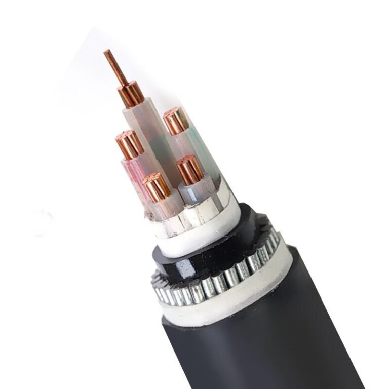
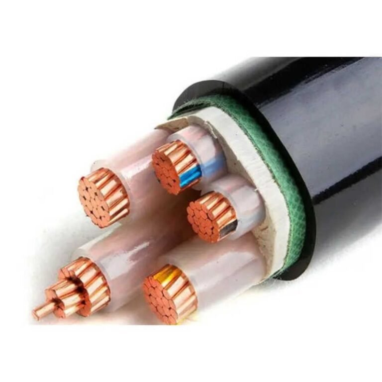
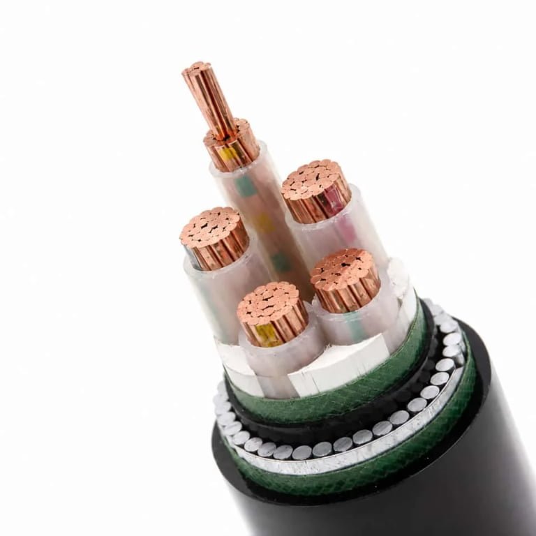
You pull a cable TV wire out of the wall and suddenly realize you have no idea if it’s the right type, the right condition, or even the right standard for the distribution amplifier you’re trying to feed. Wrong call here and you’re looking at signal degradation across a whole trunk run, noise complaints from every drop, or a re-pull that costs more in labor than the cable ever did.
Cable TV wires are almost always coaxial cables — a center copper conductor surrounded by a dielectric insulator, a metallic shield layer, and an outer jacket. In residential and light commercial installations, RG-6 is the dominant type: roughly 6.86 mm in outer diameter, rated at 75-ohm impedance, with a white or black polyethylene jacket and a visible braided or foil shield underneath.
What most people don’t realize is that the external appearance — jacket color, diameter, braid texture — tells you far more about performance than any label printed on the box. Once you know what to look for, you can read a cable’s likely attenuation, shielding class, and installation suitability just by looking at it and measuring it. That’s what this article breaks down.
The Four-Layer Internal Structure of a Coaxial Cable TV Wire
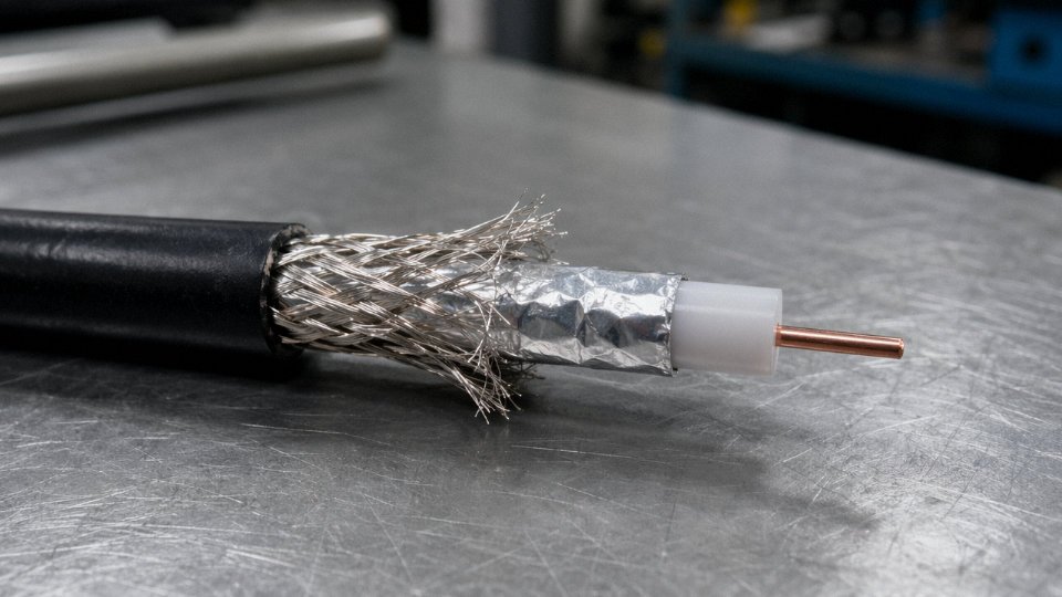
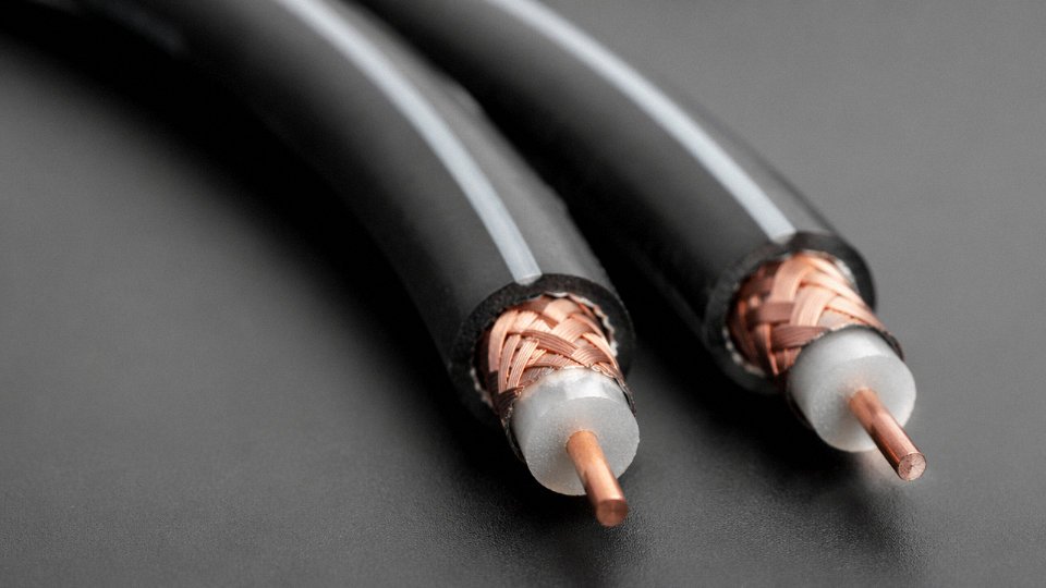
Cut open any RG-6 cable and you’re looking at four distinct layers, each doing a specific job. Get one of them wrong — wrong material, wrong geometry, wrong density — and the whole system pays for it in signal loss, interference, or premature failure. Here’s what each layer actually is and why it’s there.
Layer 1: The Center Conductor
This is the signal path. For RG-6, the center conductor diameter typically runs 1.0–1.6 mm depending on the specific construction standard and the manufacturer’s target impedance tolerance. You’ll find two main materials in the field: bare or tinned solid copper, and copper-clad steel (CCS).
CCS gets used heavily on aerial and long outdoor runs because the steel core adds tensile strength — it resists the mechanical creep and sag that a soft copper conductor develops under its own weight over a 30–40 meter span between poles, especially in seasonal freeze-thaw cycles. The tradeoff is that steel’s conductivity is lower, so at high frequencies where the skin effect pushes current to the outer surface of the conductor anyway, the difference in signal loss is modest. For short indoor drops — a 10-meter run from a wall plate to a TV — solid bare copper is preferred because it terminates more cleanly with F-connectors and has marginally lower attenuation.
Copper-clad steel center conductors are unsuitable for any cable TV applicationFalse
CCS conductors are widely used and specified for aerial and longer outdoor coaxial runs precisely because of their superior tensile strength. Signal loss differences versus solid copper are acceptable within typical residential and commercial cable TV span lengths.
Layer 2: The Dielectric Insulator
Surrounding the center conductor is a foamed or solid polyethylene sleeve — visually a creamy off-white color, slightly compressible if you press it between your fingers (the foamed version, anyway). Its job is geometrically critical: it spaces the center conductor precisely at the center of the shield assembly, and that spacing directly controls the cable’s characteristic impedance. Change the foam density inconsistently and your 75-ohm cable starts wandering toward 72 or 78 ohms in spots, which causes signal reflections. Foamed PE dielectric reduces signal attenuation compared to solid PE because the air bubbles lower the dielectric constant — that’s the practical reason it’s now standard in quality RG-6 rather than solid PE. Maintaining consistent foam density along the entire production run is one of the more demanding process controls in coaxial manufacturing; at Jinda’s production lines, dielectric outer diameter is monitored continuously with laser gauges, with concentricity tolerances held tight enough to keep impedance variation within ±1–2 ohms across the cable length.
Layer 3: The Shield Assembly
This is the layer that looks the most complex when you cut the cable open. Directly over the dielectric sits an aluminum foil layer — usually a mylar-bonded aluminum tape, helically or longitudinally applied — which provides continuous coverage against high-frequency EMI. Over that sits a braided layer of aluminum wire or tinned copper wire, which adds both lower-frequency shielding and mechanical protection for the foil underneath.
Standard dual-shield construction (one foil, one braid) typically achieves 85–95% braid coverage and is adequate for most residential cable TV environments. Quad-shield construction adds a second foil wrap and a second braid layer. Cross-sectionally it looks noticeably denser — more material, more layers visible. Quad-shield is specified in installations near strong RF sources (broadcast transmitters, industrial equipment, dense cellular infrastructure) and can achieve shielding effectiveness above 95 dB, which matters when you’re trying to keep ingress noise out of the return path in a two-way cable system.
Layer 4: The Outer Jacket
The jacket color is often the first thing a technician notices: white for most indoor residential cable, black for outdoor and direct-burial runs. Plenum-rated CMR/CMP cables tend toward light grey or off-white, dictated partly by the different jacket compound rather than any universal standard. Indoor jackets are typically flexible PVC, sometimes formulated to flame-retardant grades required by local building codes. Outdoor jackets switch to PE or LLDPE — harder, less flexible when cold, but UV-stabilized and moisture-resistant in a way that PVC simply isn’t after a few years of sun exposure.
What You See When You Strip It
Strip the jacket back 25–30 mm and the braid fans out, dull silver-grey. Fold it back carefully and the foil underneath catches the light — it’s thin and tears easily if you’re not deliberate. Peel the foil away and the white dielectric is clean and smooth underneath. Trim the dielectric back to expose the center conductor, and if it’s CCS you’ll notice it’s stiffer than pure copper under the flush cutter. Each layer tells you something about the cable’s intended application before you’ve even looked at the spec sheet.
RG-6 vs. RG-59 vs. RG-11: How the Three Main Cable TV Wire Types Differ in Appearance and Performance
Walk into any building built before roughly 1995 and pull a coaxial cable off the wall — there’s a reasonable chance it’s RG-59. It’s the slimmest of the three common types, with an outer diameter around 5.8 mm, a center conductor that measures roughly 0.6 mm, and a noticeably soft, flexible jacket that bends easily in your hand. That flexibility was actually a selling point during analog cable TV rollouts when installers were routing cable through tight conduit and around sharp corners. The problem is physics: that thin conductor bleeds signal. RG-59 loses somewhere around 7.5 dB per 100 feet at 900 MHz, which adds up fast on any run longer than 30–40 meters. For legacy CCTV systems running composite video at lower frequencies, it still works acceptably. For anything carrying modern digital or satellite signals above 1 GHz, it’s the wrong tool.
RG-6 is what you’ll find in virtually every residential and commercial cable TV installation built or retrofitted in the past 25 years. The outer diameter sits at approximately 6.86 mm — noticeably thicker than RG-59 but not dramatically so — and the center conductor is around 1.0 mm solid copper or copper-clad steel, depending on the grade. That conductor size, combined with better dielectric geometry, is why RG-6 cuts attenuation to roughly 5.5 dB per 100 feet at 900 MHz and handles signals cleanly up to about 3 GHz. It’s slightly stiffer than RG-59, which catches some installers off guard when they’re trying to make tight bends near wall plates, but it’s still manageable in most residential runs. The center pin at any F-connector termination will visually confirm the type: RG-6’s pin protrudes noticeably further and looks more substantial than the thinner pin on an RG-59 connector.
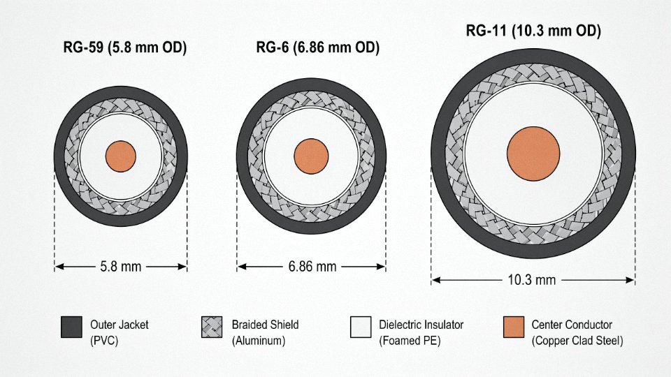
RG-11 is a different beast entirely. At roughly 10.3 mm OD, it’s nearly as thick as a standard garden hose, and it handles like one too — stiff, heavy, and genuinely difficult to route through finished walls without conduit. Nobody installs RG-11 for a bedroom TV drop. It exists for trunk runs: underground feeder lines, aerial distribution between buildings, long horizontal spans where preserving signal level over 100 to 300 meters is the primary engineering requirement. Attenuation per 100 feet drops to somewhere in the 3–4 dB range at 900 MHz (exact figure depends on conductor construction and dielectric grade), which is what justifies the added cost, weight, and installation difficulty on those long hauls.
| Type | OD (approx.) | Center Conductor | Impedance | Typical Use | Max Frequency | Attenuation @ 900 MHz / 100 ft |
|---|---|---|---|---|---|---|
| RG-59 | ~5.8 mm | ~0.6 mm | 75 Ω | Legacy CCTV, analog cable TV | ~1 GHz | ~7.5 dB |
| RG-6 | ~6.86 mm | ~1.0 mm | 75 Ω | Residential/commercial cable TV, satellite | ~3 GHz | ~5.5 dB |
| RG-11 | ~10.3 mm | ~1.6 mm | 75 Ω | Trunk runs, aerial/underground feeder | ~3 GHz+ | ~3–4 dB |
Attenuation values are representative; actual figures vary with conductor material, dielectric type, and manufacturing tolerances.
RG-6 accounts for over 90% of residential cable TV installations worldwideTrue
RG-6's balance of signal performance up to 3 GHz, manageable diameter, and cost-effective manufacturing has made it the de facto standard for residential coaxial drops since the mid-1990s, confirmed across industry installation standards including SCTE and IEC guidelines.
Identifying Cable Type in the Field Without Any Tools
The jacket printing is your first stop. Reputable manufacturers print the cable designation — “RG6/U”, “RG59/U”, “75 OHM”, sometimes the sweep-tested frequency range — directly on the outer jacket every meter or so. On older or cheaper cable, that printing fades or was never clear to begin with, in which case you go physical. RG-11 is immediately obvious by its stiffness and girth. Distinguishing RG-59 from RG-6 is trickier by eye, but if you have a terminated end, look at the center pin at the F-connector — RG-6’s pin extends roughly 6–8 mm beyond the connector body, while RG-59’s pin sits noticeably shorter and thinner. A caliper on the jacket settles any argument in about ten seconds.
Jinda’s Product Range Across All Three Types
Jinda manufactures RG-59, RG-6, and RG-11 across standard and application-specific variants. Jacket colors are customizable — black for outdoor and direct-burial runs, white for interior finished spaces, and custom colors for project-specific coding requirements. Outdoor grades use UV-stabilized polyethylene or PVC compounds that hold up through seasonal temperature swings and prolonged sun exposure, which matters more than some procurement specs acknowledge, especially in climates with intense UV or significant freeze-thaw cycling. Messenger wire variants, with an integrated steel support wire bonded to the jacket, are available for self-supporting aerial spans — eliminating the separate lashing hardware that field crews often skip or install incorrectly anyway. For bulk project procurement, all three types are available on standard reels or in cut lengths, with documentation packages covering test reports, conductor material certificates, and compliance to relevant international standards.
Connector Anatomy: How F-Type, BNC, and RCA Fittings Change the End Appearance of Cable TV Wires
Walk into any cable TV installation job and the first thing a technician grabs isn’t the cable — it’s the connector bag. The fitting on the end of a coaxial cable tells you almost everything about where that cable is going, what equipment it’s feeding, and how much abuse it’s expected to handle. Get the connector wrong and you’ll either pull signal from a joint that corrodes in six months or show up to a broadcast rack with the wrong bayonet fitting and no quarter-turn lock.
F-Type Connectors: What the Dominant Standard Actually Looks Like
The F-type is the workhorse. Roughly 95% of residential and distribution cable TV terminations worldwide use it, and its visual signature is unmistakable: a threaded barrel — either smooth or hexagonal in cross-section — typically 18–22 mm long, with a silver or gold-toned body made from zinc alloy or brass. The thread pitch is 3/8-32 UNS, standardized well enough that mixing brands rarely causes thread damage, though the hex body variants give you a cleaner torque grip with a 7/16-inch wrench.
The most distinctive feature is the center pin, which is not a machined pin at all. It’s the bare stripped center conductor of the coaxial cable itself, protruding 5–7 mm beyond the connector face. That single fact explains why cable preparation quality matters so much: a conductor that’s nicked, bent, or cut too short will give you an intermittent contact even after the connector looks perfectly installed.
The three F-connector sub-types differ visually in ways that matter operationally. A compression F-connector has a smooth, closed back end — the compression sleeve has already locked the body against the cable jacket, producing the cleanest appearance and, more importantly, a weatherproof mechanical seal. These are what professional installers should use on any outdoor drop. A crimp F-connector shows a visible metal crimp ring at the cable entry point, a ring that has been deformed with a ratchet crimper to grip the cable. Functional, but the seal is less consistent. Twist-on F-connectors are identifiable because the barrel rotates freely on the cable after installation — there’s no mechanical lock to the jacket. They belong in exactly one place: a temporary indoor test connection. In practice, you find them in the field far more often than you should, usually on installations done quickly and cheaply, and they account for a disproportionate share of signal complaints from moisture ingress.
Compression F-connectors provide better weatherproofing than twist-on F-connectors for outdoor cable TV installationsTrue
Compression connectors use a mechanical sleeve that locks and seals against the cable jacket, while twist-on types have no fixed mechanical grip on the jacket, leaving a gap that moisture can penetrate over time — a known failure mode documented in cable industry installation standards.
BNC Connectors: Professional Broadcast and CCTV Terminations
BNC connectors are visually heavier and more deliberate-looking than F-types. The cylindrical silver-toned body runs roughly 15 mm in diameter, compared to the slimmer F-type profile, and the bayonet locking collar with two protruding pins is the defining visual feature. Quarter-turn, and it locks. Another quarter-turn, and it releases. No threading, no tools needed — which is why broadcast and CCTV rack environments favor it heavily. If you’re specifying cable for a security camera system or a video distribution headend rather than a residential drop, BNC is frequently the right call.
RCA Connectors: Consumer Context, Identical Cable
RCA phono plugs at cable TV outputs signal consumer AV context. The yellow connector carries composite video; the cable underneath is the same 75-ohm coaxial construction. The connector body is smaller and softer-feeling than an F-type, with a central pin surrounded by an outer sleeve. No locking mechanism. They’re not meant for repeated connection cycles in an installation context.
Outdoor Weatherproofing Changes the Visual Profile Significantly
On any outdoor F-type connection — a splitter housing, a ground block, a wall penetration point — the bare connector is almost never what you see. Properly installed, it’ll be covered with a rubber boot slipped over the cable before the connector is installed, or wrapped in self-amalgamating tape (the gray or black rubbery tape that fuses to itself), or capped with a gel-filled weatherproof cap that snaps over the threaded joint. These measures add visible bulk to the connection point and make it harder to identify the connector type without removing them — but that bulk is exactly what separates a connection that lasts five years outdoors from one that corrodes and degrades by the second rainy season.
Procurement: Pre-Terminated Assemblies vs. Bulk Cable
For distribution contractors and project procurement teams, the choice between pre-terminated cable assemblies and bulk cable with field termination kits has real cost and quality implications. Pre-terminated assemblies guarantee consistent connector installation quality — factory compression tooling and pull-testing are far more reliable than field crews working under time pressure. Bulk cable paired with field kits gives flexibility in run lengths but introduces variability. Jinda supplies both formats: bulk RG-6 and RG-11 on standard drum sizes for large installations, and pre-terminated assemblies with compression F-type, BNC, or RCA ends for distribution and OEM customers who need ready-to-install product. Lead times and minimum order quantities differ between the two formats, so it’s worth clarifying application requirements early in the procurement conversation.
Drop Cables, Trunk Cables, and Distribution Cables: Recognizing Cable TV Wire Roles by Their Physical Form
Cable TV infrastructure is not a single wire from the broadcast facility to your television. It’s a hierarchy — and each tier in that hierarchy has a physically distinct cable form that reflects its job. If you’re procuring for a greenfield network build or retrofitting aging coax plant, understanding what each segment looks like (and why) prevents costly specification errors.
Trunk and Feeder Hardline: The Cables Most People Never See
At the headend and running down the major trunk routes, the cable looks nothing like the RG-6 most people associate with cable TV. These are hardline coaxial cables — 0.500-inch or 0.750-inch aluminum-sheathed designs where the outer conductor is a seamless or corrugated aluminum tube, not a braided shield. Pick one up and it genuinely feels like rigid copper pipe. There’s almost no flex; bending radius is measured in feet, not inches. The dielectric is typically foam polyethylene, and the center conductor is usually aluminum-clad steel or solid aluminum.
These cables are specified for trunk spans that may run hundreds of meters between amplifier stations. Signal attenuation must stay low enough that amplifier spacing remains practical, and the rigid aluminum sheath provides both structural integrity for aerial lashing and near-total EMI isolation. You won’t find these at a hardware store. They’re purchased through infrastructure channels in cut lengths or on large reels, and installation requires specialized cable preparation tools and connectors — not the hand-crimp F-connectors used on drop cable.
Feeder and Distribution Cables: The Semi-Flexible Mid-Tier
Between the trunk amplifiers and the neighborhood tap boxes, distribution cables are typically semi-flexible hardline or heavy-gauge RG-11 variants with foam-dielectric cores. Outer diameters commonly run in the 0.412-inch to 0.500-inch range depending on the specific design. The jacket is almost always black PE, rated for direct UV exposure.
For aerial runs — which is most outside plant work in practice — these cables are lashed to a separate steel messenger strand using a spiral lashing machine, or they come factory-bonded in a Figure-8 or “self-supporting” configuration where a galvanized steel messenger wire shares a common PE sheath with the coax, creating a distinctive twin-lobe cross-section. Seen from the end, it looks like two circles joined at the hip. The steel lobe handles the mechanical load across the span; the coax lobe carries the signal. This is not decorative. A plain coaxial jacket will creep and eventually fail under its own weight across a 200-foot aerial span without that messenger support.
Drop Cable: The Familiar Last-Mile Run
The drop cable — RG-6 in the vast majority of residential and light-commercial installations — runs from the tap box on the pole or pedestal into the structure. Outdoor aerial drop is round, black, UV-stabilized PE jacket, often with a steel or galvanized messenger lashed or bonded alongside it. Once it enters the building, the jacket color typically switches to white for aesthetic reasons. That’s the only change in most cases; the electrical construction is identical.
RG-6 coaxial cable is used in over 90% of residential cable TV drop installations globallyTrue
RG-6 with 75-ohm impedance and approximately 6.86 mm outer diameter became the residential standard through the 1990s and 2000s, displacing RG-59 due to better high-frequency attenuation performance — roughly 5.5 dB per 100 feet at 900 MHz versus RG-59's approximately 7.5 dB at the same frequency.
In-Wall Distribution Cable: Where Fire Rating Becomes Non-Negotiable
Inside the structure, RG-6 transitions to CMR-rated riser cable or CMP-rated plenum cable depending on the air-handling environment of the installation space. Plenum cable has a significantly stiffer jacket — usually FEP or a low-smoke PVC compound — and feels noticeably more rigid than outdoor-rated coax of the same core dimensions. The jacket surface tends to be smoother and slightly glossy compared to the matte-black texture of outdoor PE.
The UL or ETL listing mark, the CMR or CMP rating, and the cable specification are all printed in recurring intervals along the jacket. If those markings are absent or illegible, don’t install it in a building. That’s not a theoretical concern — code inspectors check, and retrofitting mis-specified in-wall cable after drywall is closed is an expensive problem.
Sourcing the Full Hierarchy From a Single Supplier
For infrastructure procurement teams working on multi-site rollouts or international builds, sourcing each cable tier from a different vendor creates quality-control fragmentation and logistical headaches. Jinda manufactures across the full coaxial network hierarchy — from heavy hardline trunk cable through semi-flexible distribution designs, RG-11 and RG-6 drop cables in both aerial and direct-burial configurations, and CMR/CMP-rated in-building distribution cable. All production runs through integrated facilities with controlled dielectric foam processes and jacket extrusion lines that maintain dimensional consistency across reel-to-reel production. For procurement teams specifying a consistent cable plant across a national or regional rollout, that vertical integration matters more than unit pricing alone.
Color Coding, Jacket Markings, and Print Lines: How to Read the Information Printed on a Cable TV Wire
Most installers glance at the print line on a coaxial jacket and ignore it. That’s a mistake. Every character printed on that jacket is there because a listing body, a safety standard, or a procurement spec required it — and being able to read it fluently will save you from pulling the wrong cable through a conduit, failing an inspection, or spending three hours re-measuring a completed run.
Jacket Color and What It Actually Tells You
Black is the default for anything that lives outside. UV-stabilized polyethylene compounds give outdoor and direct-burial cables that characteristic matte or slightly waxy black finish. White or ivory jackets are the indoor standard — you’ll see these on virtually every RG-6 reel sold for in-wall residential drops. The distinction matters practically: put a white PVC-jacketed cable in a conduit run across a rooftop and you can expect the jacket to chalk, crack, and eventually expose the foil within a few seasons, depending on climate and UV load.
Grey usually signals plenum-rated construction. Plenum cables use low-smoke, flame-retardant jacket compounds — typically fluoropolymer or plenum-grade PVC — and that material tends to come out a neutral grey. Not always, but often enough that a grey coax in a ceiling grid is worth checking for a CMP rating before assuming it’s a standard CMR drop cable.
Custom colors — red, blue, orange, yellow — show up in operator-managed networks where installers are laying multiple cable generations or service tiers in the same pathway. An operator might run orange for trunk feeds and blue for subscriber drops to make splicing and troubleshooting faster. No universal standard governs these color choices; they’re project-specific, so always get the color scheme documented in the job specification before ordering.
Decoding the Print Line
A compliant coaxial cable jacket carries a continuous print line that repeats roughly every 600–900 mm. Under UL and ETL listing requirements for North American supply, that line must include the cable type designation (such as COAXIAL RG6/U), the conductor size in AWG or mm², a voltage rating, the flame-resistance class (CM, CMR, or CMP, in ascending order of smoke and flame performance), the listing mark itself, and the manufacturer’s name. CE-marked cables for European projects follow EN 50117 and related directives, with slightly different nomenclature but the same general structure.
The frequency and impedance statement — 75 OHM for cable TV distribution — is easy to overlook but critical. If you’re pulling cable from a mixed inventory and you find 50 OHM printed on a jacket, stop. That cable is built for RF test equipment, two-way radio infrastructure, or data networking. Running broadcast cable TV signals on 50-ohm cable introduces impedance mismatches that produce reflections and visible signal degradation. It’s the kind of problem that shows up as intermittent pixelation and takes an annoying amount of time to diagnose.
Sequential Footage Markers
Most coaxial cable ships with sequential footage or meter marks printed at 1–2 foot intervals (or every 0.5 m on metric-spec reels). These aren’t decorative. An experienced installer reads the marker at the point of termination, subtracts the reel’s starting number, and knows the run length without unrolling a tape measure. For record-keeping on multi-unit residential or commercial projects, photographing the jacket print at each termination point — showing the footage number, the cable designation, and the listing mark — creates a traceable installation record that satisfies most project handover requirements and building inspectors.
Certification Marks for International Projects
For cross-border procurement, the certification stack on the jacket is part of your compliance documentation. UL listing covers North American markets. CE marking covers the European Economic Area. RoHS and REACH compliance markings indicate restricted substance compliance relevant to waste and customs regulations in the EU, UK, and increasingly in other jurisdictions.
Jinda cables supplied for international projects carry UL listing, CE marking, and RoHS compliance documentation as part of a standard documentation package for customs clearance and project handover.True
Jinda maintains multi-region certification across its coaxial cable product lines to support procurement managers handling international tenders and project documentation requirements.
Procurement officers should treat the jacket print line as a living compliance record, not background noise. Photograph it at delivery, photograph it at termination. If a substitution is made mid-project and the new reel carries a different listing mark or flame-resistance class, that’s a specification deviation — document it or reject the reel. The print line is the one part of the cable that tells you everything about what it is and whether it belongs in your installation.
Environmental and Installation Conditions That Change How Cable TV Wires Look Over Time
Cable that looked perfectly fine coming off the reel can tell a completely different story five years later. Aging, weather, and installation abuse leave visible fingerprints on coaxial cable — and learning to read those signs quickly is one of the more underrated field skills in cable plant maintenance.
UV Degradation: The Jacket Tells You First
Unprotected PVC jackets on outdoor runs are the first casualty of direct sun. Within roughly 5–7 years of continuous UV exposure, the jacket surface oxidizes and chalks — you can actually rub a whitish powder off the surface with a gloved finger. The color shifts from black or grey toward a washed-out brownish-grey, and the material loses the slight give it originally had. What looks like surface cosmetics is actually structural: a chalked PVC jacket is brittle underneath, and any flex from wind loading or maintenance disturbance will crack it longitudinally rather than bend it cleanly.
UV-stabilized black PE jackets behave very differently. The carbon black loading in a properly formulated PE compound acts as a UV absorber, and a good outdoor-rated cable should retain its color and flexibility for somewhere in the 10–20 year range, depending on geographic latitude, cable orientation (south-facing horizontal runs get punished hardest), and whether the cable runs in open air or through conduit. The visual difference between a degraded PVC jacket and a healthy PE jacket is obvious side by side — one looks faded and dusty, the other stays uniformly matte black and cuts cleanly without crumbling.
Moisture Ingress: What You See at the Cut End
A clean cut on a healthy cable shows a bright, shiny center conductor — copper or copper-clad aluminum, either way it should look metallic and uniform. If the cut end shows a milky haze, a greenish-bronze discoloration, or visible oxidation creeping back from the conductor surface, moisture has been inside that cable. Water typically enters through a jacket crack or, more commonly, through an outdoor F-type connector that was never properly weatherproofed or whose compression seal has aged out.
This is a clear field rejection criterion. No amount of re-termination fixes oxidized conductor or corroded braid — the damage is done for some length back from the entry point, and that section needs to come out.
A greenish or milky center conductor visible at a coaxial cable cut end indicates moisture-induced oxidation and warrants cable replacement in that run segment.True
Moisture penetration causes galvanic oxidation on copper and copper-clad aluminum conductors and degrades the foamed dielectric, increasing signal attenuation and impedance irregularity. The discoloration is a reliable visual indicator of electrical compromise.
Crush Damage and Kinking: What You Can’t Always See
External flat spots from a cable stapled too tight, run under a door, or driven over by a cart are obvious. What isn’t obvious is the internal damage. The foamed polyethylene dielectric deforms permanently under crush loading, and the center conductor shifts off-axis — sometimes contacts the braid. The result is an impedance discontinuity that shows up as a return loss spike on a sweep test. The cable looks merely dented from outside. In practice, any visible flat spot on a coaxial cable run is worth sweeping before signing off on an installation.
Connector Corrosion: A Visual Pre-Test
Outdoor F-type connectors corrode in predictable ways. The aluminum ferrule on a compression connector develops a white powdery aluminum oxide deposit. The center pin, if it’s brass, goes green. Either condition can add somewhere in the 3–6 dB range of insertion loss at 1 GHz — and that range widens in humid coastal environments versus dry inland sites. The visual tells you the test is necessary before you even pull out the meter.
Rodent and Mechanical Abrasion Patterns
Gnaw marks from rodents are distinctive — paired semicircular indentations through the jacket, sometimes exposing braid or foam. Abrasion damage at conduit entry points looks different: longitudinal scraping and jacket thinning in a narrow band at the conduit lip, often with metallic transfer marks from the conduit edge. Both failure modes are addressable with armored construction — a corrugated steel or aluminum tape layer under the outer jacket puts a physical barrier between the cable internals and mechanical attack.
For outdoor plant with genuine longevity requirements, flooding compound injected into the braid layer during manufacture stops capillary water migration even when the jacket is breached. Double PE jacket constructions add a second line of defense. These aren’t features that show up in a catalog photo, but they’re the difference between a cable that holds up for 20 years in a wet, sun-exposed aerial run and one that’s a maintenance call waiting to happen.
Fiber-Optic and Hybrid Cable TV Wires: What Modern HFC Network Cables Look Like
Walk into a cable TV headend today and you’ll see two completely different families of cable running side by side — and if you only know what RG-6 looks like, the fiber side of the room will look almost alien.
How HFC Networks Split the Physical Plant
Most active cable TV networks worldwide now operate as hybrid fiber-coaxial (HFC) systems. Single-mode fiber carries the signal from the headend out to fiber nodes scattered through neighborhoods, typically serving anywhere from 100 to 500 homes depending on how aggressively the operator has segmented the plant. From the node outward, the network reverts to familiar coaxial — RG-11 on the distribution feeder, RG-6 on the subscriber drop. The fiber portion and the coaxial portion look nothing alike, which matters enormously when a field tech opens a cabinet or splice enclosure and needs to know immediately what they’re handling.
What Fiber Trunk Cables Actually Look Like
A typical cable TV trunk fiber cable is round or figure-8 (the figure-8 variant integrates a steel messenger strand for aerial lashing), with an outer diameter ranging from roughly 8 mm on a 12-fiber count up to 18–20 mm on a 144-fiber trunk, though exact dimensions depend on buffer tube count, armor layer, and jacket wall thickness. The jacket is most commonly black for outdoor/direct-burial runs or orange for indoor/riser-rated fiber — orange is hard to miss next to a black coaxial bundle. Cut the end and you’ll find gel-filled or dry loose buffer tubes, each containing several color-coded 250 µm fibers, surrounding a central aramid or fiberglass strength member. There is no copper conductor, no braid, no foil. The cross-section looks almost soft and textile-like compared to the rigid metallic layers of a coaxial cable.
Terminations confirm the difference instantly. Cable TV trunk fiber almost universally terminates in SC/APC connectors — green-bodied, with an 8° angled ceramic ferrule — or occasionally SC/UPC, which uses a blue housing. You’ll never see a threaded center pin. You’ll never feel the slight weight of a machined brass F-connector body.
Telling Fiber from Coax at a Node or Cabinet
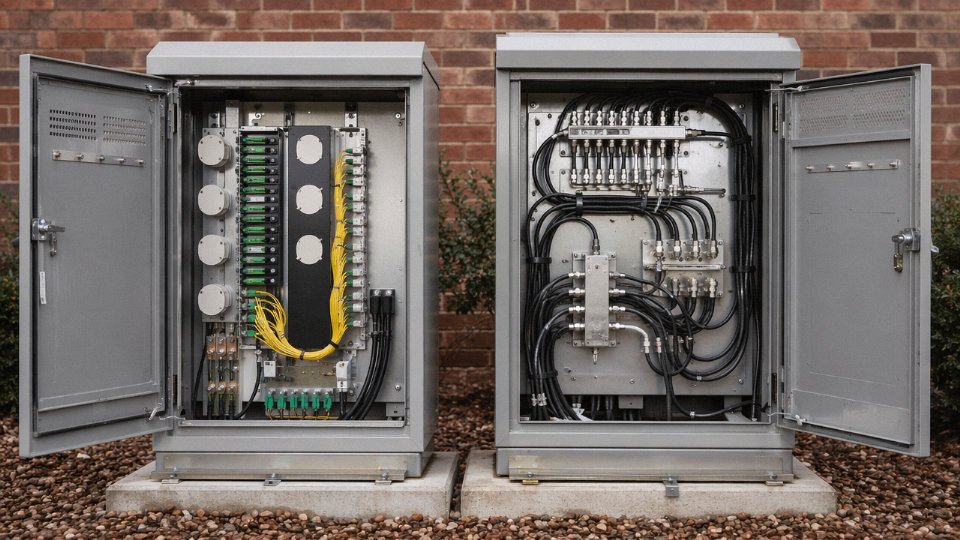
At a fiber node cabinet, the visual transition is unmistakable once you know what to look for. Fiber patch cables plug into SFP transceivers or optical receivers via those colored SC connectors; the ports are smooth, rectangular, and latch with a small plastic tab. Coaxial ports — for the RF output side feeding the distribution network — are threaded hardline interfaces or standard F-type ports. A technician can identify the fiber/coax boundary in seconds just by looking at connector type and port geometry. In practice, a good habit is to check cable jacket color and stiffness before touching anything: fiber is noticeably more flexible and lighter per meter than hardline coaxial.
Hybrid Cable Assemblies
Some composite installation cables go a step further and combine both worlds in a single sheath. These hybrid assemblies — used increasingly in fiber-deep and FTTC builds — typically present a larger oval or circular cross-section, often 15–25 mm across, with a multi-compartment interior that’s visible the moment you make a straight cut. One section of the cut end shows the familiar coaxial construction with its center conductor and braid; the adjacent compartment shows the gel-tube fiber bundle. The jacket is usually black PE with printed identification specifying the fiber and coaxial content separately.
The DOCSIS Paradox: Identical Wire, Radically Different Performance
Here’s something worth flagging for anyone specifying or auditing a cable TV plant: the RG-6 drop cable entering a home on a DOCSIS 4.0 network looks physically identical to the RG-6 that carried analog cable TV in the 1990s. Same diameter, same black jacket, same F-connector. The difference is entirely in what that cable connects to at each end. Judging network capability by the appearance of the drop wire is a reliable way to reach the wrong conclusion.
A DOCSIS 4.0 network can deliver multi-gigabit speeds over the same RG-6 coaxial drop cable used in legacy analog cable TV systems.True
DOCSIS 4.0 specifications support downstream capacity exceeding 10 Gbps using extended spectrum (up to 1.2 GHz) over existing coaxial infrastructure; the physical cable is unchanged, while CMTS and modem electronics carry the performance improvement.
Jinda’s HFC-Ready Cable Constructions
Shandong Jinda produces fiber optic cables specifically designed for HFC trunk and distribution deployment, including GYTA (stranded loose-tube with aluminum-polyethylene laminate sheath), GYTS (steel-tape armored for direct burial), and GJYXCH (indoor/building entry tight-buffered construction). These are manufactured alongside Jinda’s coaxial product range, which means a procurement manager sourcing for an HFC network build can consolidate both the fiber trunk and the coaxial distribution side from a single supplier — something that simplifies documentation, quality auditing, and logistics considerably on large international projects.
Buying and Specifying Cable TV Wires: Key Physical Parameters for Procurement and Project Specification
Getting a cable TV wire specification wrong at the procurement stage costs far more than the cable itself. Rework, signal failures, failed inspections, and emergency re-orders eat into project margins fast. The physical characteristics covered throughout this article translate directly into line items on an RFQ — and every one of them needs to be explicit.
Core Specification Parameters: Define Every Layer
Start with cable type. RG-6 covers the overwhelming majority of residential and light commercial installations; RG-11 is specified where runs exceed roughly 60–90 m and you need to hold signal level, particularly above 500 MHz. Once you’ve fixed the type, lock down the conductor material: bare copper (BC) gives you the best conductivity and long-term corrosion resistance, copper-clad steel (CCS) is cheaper and stronger in tension but measurably worse at high frequencies due to the skin effect, and bare copper-clad steel (BCCS) sits somewhere in between. For any HFC or DOCSIS 3.1 deployment running signals above 750 MHz, CCS is a poor choice regardless of price.
Dielectric type affects both attenuation and the cable’s outer feel. Solid PE is denser and stiffer — you can feel it when you coil the cable. Foam PE cuts attenuation noticeably (the air-laden structure lowers the dielectric constant) but is more sensitive to crush damage during installation. Foam-skin dielectric is a layered compromise that most quality RG-6 products use today.
Shield configuration is where specifications get sloppy in a lot of RFQs. Single-braid, dual-shield (foil + braid), and quad-shield are not interchangeable. In a residential drop from a pedestal to a wall plate, dual-shield is usually adequate. In any environment with significant RF noise — near industrial equipment, in a multi-tenant building with dense wireless infrastructure, or in a headend room — quad-shield’s near-complete EMI rejection matters.
Quad-shield coaxial cable provides shielding effectiveness above 95 dB, compared to roughly 85% physical coverage on a single-braid design.True
Quad-shield designs layer two foil and two braid layers, achieving near-complete EMI rejection above 95 dB; standard single-braid coverage ranges from 85% to 100% physical coverage, which does not translate directly to equivalent shielding effectiveness at all frequencies.
Jacket material and color need to be specified together. PVC is the standard indoor choice; direct-burial runs need a UV-stable polyethylene or LLDPE jacket, and plenum-rated cable requires a low-smoke, flame-retardant compound (FRPE or equivalent) that meets local building codes. Black jackets age better outdoors than white. Specify operating frequency range — a 3 GHz-rated cable for a DOCSIS 3.1 plant looks nearly identical to an 862 MHz cable from the outside, but the internal geometry and dielectric quality are different.
Reel Sizes, Packaging, and Site Logistics
Standard RG-6 comes on 500 ft (152 m), 1,000 ft (305 m), and 1,000 m reels for installer-grade work. Bulk deployment — aerial strand lashing across a subdivision, for instance — typically moves to wooden drums of 2,000–5,000 m. Drum size directly affects shipping weight, pallet configuration, and customs documentation. A 5,000 m drum of RG-6 can weigh 180–260 kg depending on jacket and construction; that changes your freight class and may require a tailgate delivery or a forklift on site. Factor this into your procurement logistics before the order is placed, not after it arrives at the dock.
Bend Radius and Pulling Tension
RG-6 has a minimum static bend radius of roughly 25 mm and a dynamic (installation) bend radius of around 50 mm. Pulling tension limits are typically in the range of 45–90 N depending on conductor material and construction — CCS handles more tension, BC is more sensitive. Exceed either limit and you get the kinking and dielectric deformation described in earlier sections of this article: the damage is usually invisible from the outside and only shows up as elevated return loss or intermittent signal.
Impedance, Testing, and Documentation
Every component in a cable TV signal path must be 75-ohm. This sounds obvious, but 50-ohm coax from an RF test kit or a wireless installation sometimes ends up spliced into a cable TV distribution run on a busy job site. The mismatch produces reflections that show up clearly on a spectrum analyzer as a standing wave ripple across the channel band. Put “75-ohm impedance, verified per IEC 60966 or SCTE 74” in every RFQ.
Ask any supplier for a full factory test report, third-party lab certification, and RoHS/REACH declarations before the order ships. Jinda supplies all three as standard documentation — factory test certificates, independent lab reports, and full material compliance declarations — so procurement teams have what they need for project record-keeping and customs clearance without chasing paperwork after the fact.
Working With Jinda on Large or Custom Orders
For projects requiring non-standard jacket colors (utility color coding, branded infrastructure builds), custom conductor configurations, or mixed-reel packaging, Jinda’s international sales engineering team works directly with specifiers to define parameters before the RFQ is issued rather than after samples fail approval. Lead times for standard constructions run roughly 2–4 weeks from order confirmation depending on volume; custom jacket compounds or specialty dielectric configurations typically add 1–3 weeks. MOQ structures are flexible at scale — worth a direct conversation if your project has unusual volume or configuration requirements.
Frequently Asked Questions About Cable TV Wire Appearance and Construction
How can I tell a cable TV wire apart from an ethernet cable just by looking at it?
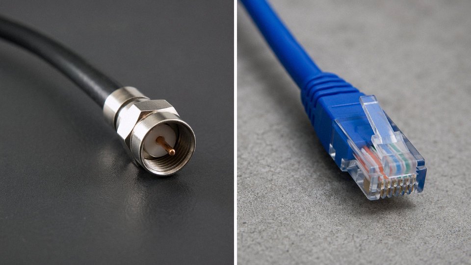
The difference is obvious once you know what to look for. A coaxial cable TV wire is noticeably round and firm — it resists bending in your hand — and terminates in a threaded metal F-connector with a single protruding center pin at its tip. Ethernet cable is softer, slightly oval in cross-section, and ends in a rectangular plastic RJ-45 plug with a spring tab you press to release it. If you strip back the end of an ethernet cable you’ll see four twisted pairs — eight individual conductors color-coded in a loose standard (orange, green, blue, brown, each with a white-striped partner). A coaxial cable end shows one thing: that center conductor, surrounded by dielectric, then shield. Hard to confuse the two once you’ve handled both.
What is the copper wire in the middle of a cable TV wire actually doing?
That center conductor is the entire signal path. Every cable TV channel — from the low-frequency return path around 5 MHz up through broadcast signals past 1 GHz on modern DOCSIS 3.1 systems — travels on that single conductor as frequency-multiplexed RF signals stacked on top of each other. Nothing else in the cable carries signal. This is why any kink, nick, or corroded contact point on that conductor degrades the whole channel lineup simultaneously rather than just one circuit. A sharp bend that deforms the conductor even slightly changes the local impedance and creates a reflection point. In the field, a bent center pin at a connector is one of the more common causes of intermittent pixelation that’s surprisingly hard to trace without a signal meter.
Why does my outdoor cable TV wire look brown and cracked?
UV exposure and repeated thermal cycling — hot summer afternoons followed by cold nights — break down unprotected PVC jacket compounds over roughly 5 to 10 years, depending on climate, UV intensity, and jacket compound quality. Once the jacket cracks, moisture gets in. Moisture oxidizes the aluminum or copper braid shield, raises contact resistance, and eventually wicks toward the center conductor. You’ll see elevated signal attenuation before you see the physical damage at the connector. If the jacket is visibly cracked or has turned from its original black to a chalky brown-gray, the cable needs replacing — not re-terminating, not patching with tape. Replace it.
A cracked outdoor coaxial jacket always means the shield underneath is already compromised.False
Jacket cracking is a reliable warning sign, but the timeline varies. A freshly cracked jacket on a recently installed cable may still have an intact shield. The real risk is moisture ingress over subsequent months. Inspection of the shield at both ends should follow any jacket damage discovery.
Can I use 50-ohm coaxial cable for cable TV if that’s what I have on hand?
No. Cable TV infrastructure is designed end-to-end for 75-ohm impedance — the headend equipment, the amplifiers, the splitters, the TV tuner input. Substituting 50-ohm coaxial (the type used in amateur radio, WiFi antenna runs, or cellular installations) creates an impedance mismatch at every interface. That mismatch generates signal reflections that cause standing waves, and the result is frequency-dependent signal loss that can range from annoying to completely unusable depending on run length. This isn’t a marginal penalty. Use 75-ohm cable.
What does quad-shield cable look like compared to standard RG-6, and when does it actually matter?
Externally, you cannot tell them apart. Same jacket diameter, same black color, same print line. You only see the difference when you strip the end: standard RG-6 has one foil layer wrapped around the dielectric and one braided shield over that, while quad-shield construction adds a second foil and a second braid on top. The braid coverage on quad-shield typically exceeds 95 dB of shielding effectiveness. In a clean suburban home run, standard dual-shield RG-6 is usually sufficient. Quad-shield earns its keep in multi-dwelling unit buildings with high RF noise floors, in any run passing near variable-frequency drives or HVAC compressor units, or wherever you’re fighting ingress interference that a signal analyzer confirms is getting in through the shield rather than degrading along the conductor.
How thick should the cable TV wire running to my home be?
Standard residential drop cable is RG-6, sitting at roughly 6.86 mm outer diameter — that’s the spec that fits virtually every F-connector and wall plate on the market. For runs under about 50 meters from the tap or distribution point, RG-6 handles the attenuation budget comfortably. If your run is longer — a detached outbuilding at the back of a large property, or a basement suite fed from a tap mounted high on an exterior wall — an installer may specify RG-11, which runs around 10 mm OD. The larger center conductor in RG-11 reduces attenuation by roughly 30–40% per unit length compared to RG-6, which matters when you’re working with limited signal headroom.
Are cable TV wires safe to cut or handle?
The RF signals themselves are at extremely low voltages and pose no shock hazard. That said, before cutting into any cable in a distribution network — particularly on the trunk or feeder side of a tap — check for DC voltage. Cable TV operators routinely power line-extender amplifiers and node equipment by superimposing DC power on the same coaxial cable, typically somewhere between 24 V and 90 V AC or DC depending on the system. Cutting a powered distribution cable without confirming it’s de-energized first is a real hazard that gets overlooked by anyone who only knows the residential side of the network. A basic coaxial DC voltage checker costs very little and should be standard kit for any field technician working outside the home drop.