Specify the wrong connector family on a cable assembly drawing and you might not find out until commissioning day — when a technician is standing in a half-built panel wondering why nothing mates. Wrong connector choice drives rework, delays, and in high-cycle or high-current applications, early contact degradation that shows up as heat, voltage drop, or intermittent faults months after handover. Procurement teams feel it as emergency spot-buy premiums; maintenance crews feel it as unplanned downtime.
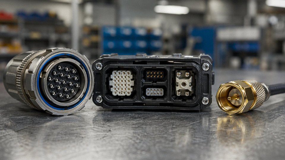
The three fundamental types of cable connectors are circular connectors, rectangular (or modular) connectors, and coaxial connectors. Circular connectors dominate rugged power and control applications; rectangular connectors handle multi-pin signal, data, and mixed-signal work; coaxial connectors carry high-frequency or RF signals in a single-axis geometry. Each family operates under distinct mechanical, electrical, and environmental constraints.
What makes this genuinely tricky is that the three families overlap more than most wiring diagrams suggest — there are circular connectors running data protocols, rectangular connectors rated for several hundred volts, and coaxial variants pushed into applications their geometry was never really designed for. Understanding where each type earns its keep, and where it starts to fail, is the difference between a cable assembly that runs for a decade and one that becomes a recurring line item on your maintenance budget.
Type 1 — Plug-and-Socket Connectors: Circular and Rectangular Variants Explained
At its core, a plug-and-socket connector is a mated pair — a male plug carrying pin or blade contacts, a female socket carrying the corresponding receptacles — engineered for repeated connect/disconnect cycles without tools, soldering, or mechanical fasteners. That sounds simple. In practice, the geometry of how those contacts meet determines everything from millivolt signal integrity to whether a 400 A feeder joint runs cool or burns through its insulation in three years.
Contact Geometry: Pin-and-Socket vs. Blade-and-Spring
Pin-and-socket contacts use a cylindrical pin inserting into a beryllium-copper or phosphor-bronze socket basket that grips the pin circumferentially. Contact resistance across a well-made pin-socket pair typically falls in the 2–10 mΩ range, though that figure shifts with plating condition, contact force (usually 0.5–5 N per contact depending on size), and whether the mating faces have oxidized from seasonal humidity cycling. Blade-and-spring contacts — a flat or formed blade pressing against one or two spring fingers — are cheaper to manufacture and tolerate slight lateral misalignment better, which is why you see them in high-volume consumer and automotive applications. The tradeoff is that spring fingers fatigue faster under vibration, and contact resistance can creep upward toward 20–50 mΩ after a few thousand cycles in a dirty environment.
Circular Connectors
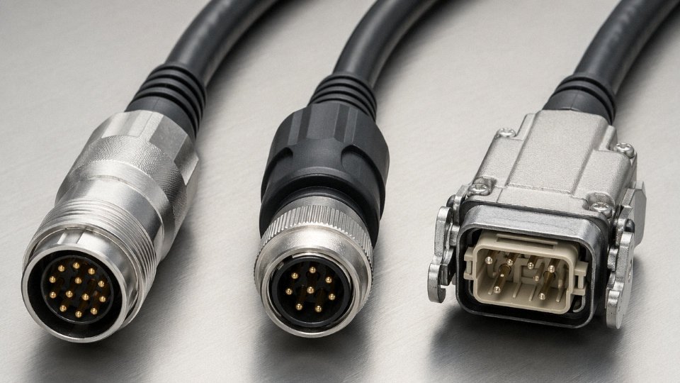
The circular shell is not just an aesthetic choice. A round cross-section distributes torsional stress uniformly when a cable is twisted or yanked at an angle — exactly the abuse that happens on a robot arm, a drag chain, or rolling stock that vibrates for 20 years. MIL-DTL-5015 and MIL-DTL-38999 are the two dominant military and aerospace circular series; the 38999 with its quadrature bayonet lock can be mated in under a second with one hand in gloves, which matters more than it sounds when you’re working inside an avionics bay. For industrial automation, the M12 four- or eight-pin circular connector has become almost universal in sensor-to-PLC wiring, and the larger M23 handles higher current runs to servo motors. Both achieve IP67 and IP68 sealing through a face-seal O-ring that compresses on mating — as long as the mating torque spec is actually followed, which in my experience maybe 60% of field installers bother to check.
Rectangular Connectors
Rectangular housings pack more poles per unit footprint, period. DIN 41612 and IEC 60603-2 Eurocard connectors are the reason rack-mounted industrial and telecom equipment can break out 96 or 160 signal contacts through a backplane with a single, repeatable blind-mate operation. The Han series (and similar heavy rectangular formats from competing manufacturers) takes this further with modular insert systems: a single housing can hold a combination of high-current power contacts, coax inserts, pneumatic push-in tubes, and fiber optic terminations. That modularity is genuinely useful when you need to disconnect a machine module at a single interface point — one pull, everything unmated cleanly. The housing shells guide and protect the contacts during that blind connection.
Engineering Parameters You Must Specify Up Front
Number of poles, contact material, plating (tin for general industrial, silver for high-cycle or high-current, gold for low-level signal), rated current per contact, rated voltage, mating cycle life, IP rating, and locking mechanism. Each one affects the others.
Circular connectors rated to MIL-DTL-38999 can achieve mating cycle life exceeding 500 cycles under the base standard, with many commercial variants rated to 5,000 cycles or more.True
MIL-DTL-38999 Series III specifies a minimum of 500 mating cycles under the military qualification; commercial-grade variants using hardened aluminum or stainless shells with gold-plated contacts are routinely rated by manufacturers to 5,000–10,000 cycles.
Circular vs. Rectangular — Quick Comparison
| Parameter | Circular | Rectangular |
|---|---|---|
| IP rating achievable | IP67–IP68 (standard with O-ring) | IP20–IP65 (housing-dependent) |
| Typical current range | 1 A (M12 signal) to 800 A (heavy circular) | 0.5 A (signal insert) to 200 A+ (Han power insert) |
| Mating cycle life | 500–10,000+ cycles | 500–5,000 cycles (insert-dependent) |
| Relative unit cost | Moderate to high | Low (DIN/Eurocard) to high (modular Han) |
| Primary use cases | Robotics, defence, railway, outdoor field equipment | Data centers, control panels, machine modules, backplane systems |
The Ampacity Derating Mistake That Causes More Fires Than People Admit
A connector’s published current rating per contact assumes that contact is operating alone. Put 12 or 24 current-carrying poles in a shared housing and they all heat each other. IEC 61984 explicitly requires derating for multi-pole connectors — the standard’s approach factors in the number of loaded contacts and the thermal resistance of the housing. A practical outcome: a 20 A-rated contact in a fully loaded 24-pole connector may need to be derated to 14–16 A in service, roughly the 70–80% range depending on housing material and ambient temperature. Specifying connector ampacity equal to cable ampacity without applying this derating is one of the most common procurement errors on multi-conductor control cable projects, and the failure mode is slow — a joint that runs slightly hot for months before the insulation inside finally softens and a phase-to-phase fault takes down the line.
Type 2 — Terminal Block Connectors: Fixed Wiring Termination for Panels and Control Systems
Terminal blocks are, in a lot of ways, the unglamorous workhorse of industrial wiring. No one takes photos of them for trade show brochures. But walk into any PLC cabinet, motor control center, or building automation panel and you’ll find rows of them — sometimes hundreds — doing the quiet, permanent work of connecting field cables to control circuitry.
The basic concept is simple: an insulated housing, usually mounted to a 35 mm DIN rail or soldered onto a PCB, grips a stripped conductor end through a clamping mechanism. There’s no mating plug on the other side. The termination is the connection. That distinction matters more than it sounds.
Clamping Mechanisms and Why the Choice Isn’t Trivial
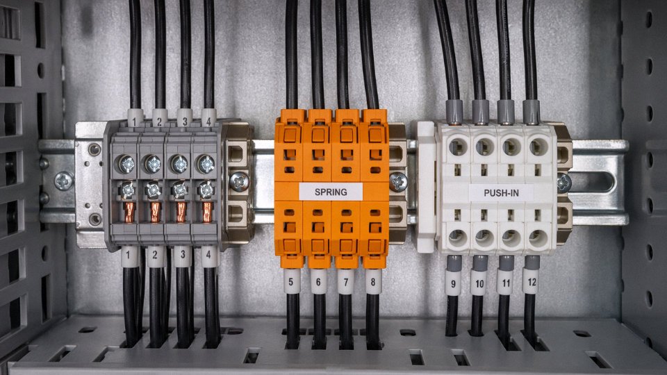
Screw-clamp terminals are the oldest design and still the most common in legacy installations. Pull-out force is high — screw torque translates directly into clamping pressure — but thermal cycling and vibration can back the screw off over time. If you’re wiring a panel that sits on the floor of a stamping press bay, or near a compressor with significant vibration signature, a screw terminal without a locking feature (captive screw, thread-locking compound) is a maintenance liability. Plan for re-torque intervals.
Spring-cage terminals, often marketed under the CAGE CLAMP name by Wago and similar designs from Phoenix Contact and others, solve the vibration problem by design. The spring maintains constant clamping force regardless of temperature swing or mechanical shock. That’s why automotive body shops, rail signaling cabinets, and any application with genuine vibration exposure have largely shifted to spring-cage. Tool-free insertion is a real productivity gain during panel build — in my experience, a two-person wiring crew can close out a 200-point cabinet noticeably faster with spring-cage than with screw terminals, though the per-unit cost is higher.
Push-in terminals take speed one step further: insert a solid conductor or a ferrule-terminated stranded wire, and the internal spring locks it immediately. No tool required at all. The catch is that loose, unferruled stranded conductors don’t work reliably here — individual strands can escape the contact zone, which raises contact resistance and, in worst cases, causes intermittent faults that are maddening to diagnose. Ferrule crimping first is not optional with push-in types on stranded wire.
IDC (insulation displacement) terminals are used less frequently in heavy industrial panels but appear regularly in lower-voltage signal wiring and structured cabling applications — they pierce the insulation directly, which is fast but commits you to a specific wire size.
Sub-Types by Function
Beyond the clamping mechanism, terminal blocks are categorized by what they do in the circuit. Feed-through types simply pass a conductor through — single level or double level. Ground (PE) terminals have a built-in connection to the DIN rail itself, providing the protective earth path without a separate jumper. Fuse terminals integrate a cartridge fuse in-line, useful for individually protecting each field device circuit without running back to a separate fuse block. Disconnect terminals add a knife switch so a single circuit can be isolated for testing or replacement while the rest of the panel stays live. That last feature alone justifies the cost in any installation where field troubleshooting under power is routine.
PCB Terminal Blocks Versus DIN-Rail Types
PCB-mount terminal blocks bridge the gap between board-level electronics and field wiring. Pitch ranges from about 2.54 mm (tight, for compact PCBs) up to 10.16 mm for heavier conductors, with wire acceptance typically covering AWG 28 down to roughly AWG 6 depending on the block. They’re everywhere in drives, sensors, and process transmitters — the point where someone in the field needs to land a 0.5 mm² signal cable onto a circuit board without soldering. DIN-rail blocks, by contrast, handle much heavier wire, up to AWG 2/0 in some power-rated versions, and are designed for the cabinet environment rather than the PCB.
Standards: What Inspectors Actually Check
IEC 60947-7-1 covers low-voltage terminal blocks for copper conductors — it specifies dielectric strength, temperature rise at rated current, and mechanical endurance. UL 508A, which governs industrial control panels in North American markets, requires that every terminal block used in a listed panel be itself recognized or listed, and it sets conductor ampacity rules that interact with the terminal block’s wire range rating. An inspector under UL 508A will check that your wire gauge matches the terminal’s listed range and that your torque values match the manufacturer’s installation spec. Using a 4 mm² conductor in a terminal rated for 2.5 mm² maximum — something that happens when someone “just makes it fit” on a rushed panel build — is a real failure point, both electrically and for compliance.
Ferrule crimping before insertion into push-in or screw terminals can reduce contact resistance by up to 30% on stranded conductorsTrue
IEC 60228 conductor class guidance and terminal manufacturer test data consistently show that ferrule crimping consolidates stranded wire geometry, increasing effective contact area and reducing resistance at the termination point. The improvement is most pronounced on fine-stranded Class 5 and Class 6 conductors.
Where Terminal Blocks Outperform Plug-and-Socket Types
When a PLC cabinet has 60, 80, or 120 I/O points, running individual plug-and-socket connectors to every one of them is cost-prohibitive and spatially impractical. Terminal blocks scale naturally — you add DIN rail, you add blocks. Individual circuit isolation during troubleshooting is built into the format rather than requiring adapter hardware. Replacement of a single terminal block in the field takes a flathead screwdriver and two minutes; swapping a damaged circular connector housing in a tight cabinet can take much longer and may require sourcing a specific mating insert.
The cost per connection point on a standard screw terminal is genuinely low — roughly a fraction of what even the simplest circular connector costs per circuit, though the exact gap depends on current rating, sourcing volume, and whether you’re comparing to mil-spec or commercial-grade plugs. For permanent, high-count, panel-mounted wiring, that economics argument alone usually settles the question before the engineering discussion even starts.
Type 3 — Splice and Butt Connectors: Inline Joining for Continuous Cable Runs
Splice connectors rarely get the same attention as circular connectors or terminal blocks in connector selection guides. That’s a mistake. In automotive harness assembly, underground infrastructure, and offshore cable repair, the splice joint is the weak point most likely to cause a latent failure — the kind that shows up three years later as a ground fault or a corroded open circuit inside a conduit you’d rather not re-pull.
Unlike plug-and-socket types, a splice connector creates no separable interface. Two cable ends go in; a continuous electrical path comes out. The joint is meant to stay there, hidden inside a harness wrap, buried under a road, or sealed inside a junction enclosure. That permanence is exactly why getting the splice type and execution right matters more than it often gets treated in procurement specs.
Crimp Butt Connectors — Getting the Die Right
The standard crimp butt splice is deceptively simple: a copper or tin-plated copper barrel, insulated in PVC, with wire stripped and inserted from each end, then crimped. What makes a crimp butt connector actually reliable is the hexagonal crimp profile. A proper hex crimp cold-welds the conductor strands to the barrel wall, creating a gas-tight contact zone that blocks oxygen ingress and resists the creep oxidation that causes resistance to climb over time. A round or B-crimp done with the wrong die doesn’t achieve that seal — contact resistance on an under-crimped joint can drift upward by 10–40% over 18–36 months depending on the environment, which in a 12 V automotive circuit translates directly to voltage drop, heat, and eventually insulation degradation.
Color coding follows SAE and UL wire range conventions: red barrels for AWG 22–18, blue for AWG 16–14, yellow for AWG 12–10. These aren’t suggestions — forcing a 14 AWG conductor into a red connector because “it mostly fits” is a vibration failure waiting to happen. Mismatched cross-sections create uneven pull-out loads, and under road vibration or engine harness flex cycles, the smaller conductor works loose first.
Heat-Shrink Solder Splice Connectors — Why Marine and Automotive Repair Love Them
These connectors solve a legitimate field problem: how do you make a splice outdoors, on a truck cab harness or a boat bilge pump circuit, without a crimping tool, and still get an acceptable moisture seal? The answer is a dual-wall polyolefin sleeve with a pre-loaded low-melt solder ring at each end and an adhesive inner lining. Apply heat — a heat gun at roughly 120–150 °C for 15–30 seconds is the typical activation window, though it varies by manufacturer and sleeve diameter — the solder wets the stripped conductor, and the adhesive liner flows outward to form a mechanical moisture barrier over the insulation.
The failure mode in cheap versions of this connector is the cold solder joint: the solder ring didn’t fully wet the conductor, often because the heat was uneven or the conductor wasn’t clean. You get a joint that reads near-zero resistance on a cold continuity check and then opens intermittently under thermal cycling. For any purchase beyond job-lot repair quantities, it’s worth pulling a few connectors from a lot, activating them, cross-sectioning with a hobby saw, and inspecting wetting under magnification before committing to volume.
Heat-shrink solder splice connectors rated for marine use must provide both an electrical connection and an ingress protection seal against moisture.True
Dual-wall heat-shrink sleeves with adhesive lining are specifically designed to flow adhesive over conductor insulation during activation, forming a mechanical moisture barrier. This dual function — soldering and sealing — is why they are specified for marine, outdoor LED, and automotive repair applications where exposed crimp splices would be unacceptable.
Mechanical Tap Splices — Aluminum Distribution Is a Different Animal
C-tap and H-tap mechanical splice connectors are the workhorses of overhead distribution and building wire work where the utility conductor stays live or re-pulling is impractical. A C-tap clamps onto a through-conductor while simultaneously accepting a tap conductor — no stripping of the main run required in many designs. That convenience matters when you’re tapping a 4/0 aluminum feeder at a transformer riser.
Aluminum conductors demand attention to two things that copper work can ignore. First, the connector must be rated for aluminum-to-aluminum (AA) or copper-to-aluminum (CA) service; a connector rated for copper only will lack the clamping force geometry needed to cold-weld aluminum’s oxide layer. Second — and in practice this step gets skipped more than it should — anti-oxidant compound (inhibitor paste) needs to be packed into the barrel or applied to the conductor before makeup. Aluminum oxide forms within minutes of stripping. Without inhibitor, you’re relying on the crimp or clamp pressure alone to break through the oxide, which it may do initially but won’t sustain under thermal expansion cycling.
Failure Modes Worth Knowing Before Specifying
| Splice Type | Primary Failure Mode | Typical Trigger | Field Consequence |
|---|---|---|---|
| Crimp butt (hex) | Under-crimp, oxidation | Wrong die, no ratchet lock | 10–40% resistance rise, heat buildup |
| Heat-shrink solder | Cold solder joint | Uneven heat, dirty conductor | Intermittent open, latent fault |
| Mechanical C/H-tap (aluminum) | Oxide layer, loosening | No inhibitor, under-torque | Arcing, hot joint at tap point |
| Molded MV heat-shrink splice kit | Void in insulation stack | Poor surface prep, contamination | Partial discharge, eventual breakdown |
For underground medium-voltage joints — say, a 15 kV or 35 kV XLPE cable repair — none of the above connectors apply directly. Those joints use factory-engineered heat-shrink or cold-shrink molded splice kits with semi-conductive screens, stress control geometry, and insulation systems tested to IEC 60502 or IEEE 404. The concept is still a splice, but the engineering involved is an order of magnitude more complex than anything discussed above, and field installation training is non-negotiable.
Offshore cable repair adds another layer: double-sealed solder splices rated for continuous submersion, or resin-filled junction enclosures, because a single moisture ingress point in a dynamic subsea environment compounds rapidly. A splice that works fine on a land installation may last six months in a cable tray exposed to seawater spray before the seal wicks and the resistance climbs.
The common thread across all three subcategories — crimp butt, heat-shrink solder, and mechanical tap — is that the connector’s long-term performance is inseparable from installation discipline. The best butt connector on the market, crimped with the wrong die or without ratchet lock confirmation, will fail faster than a mediocre connector installed correctly. Procurement can specify the hardware; process control determines the outcome.
Head-to-Head Comparison: Selecting the Right Connector Type Against Six Engineering Criteria
No single connector family dominates across all applications. The right choice depends on six operational realities — and getting even one wrong typically shows up as downtime, failed audits, or a splice joint that turns into a resistive heater inside a conduit. Here is how the three types stack up where it actually matters.
Criterion 1 — Reconnectability
Plug-and-socket connectors are the obvious choice anywhere equipment gets swapped, serviced, or moved. Circular connectors rated for 500–10,000 mating cycles mean a drive motor can be disconnected and reconnected dozens of times without degrading the joint. Terminal blocks allow circuit-level isolation with nothing more than a flathead screwdriver — useful in panel wiring where individual feeders need to be opened periodically but the block itself stays fixed to the DIN rail. Splice and butt connectors are a different animal entirely: once a heat-shrink solder splice is reflowed or a hex-crimp is set, you are not opening that joint again without cutting the cable. That is fine for underground duct runs where reconnection was never the design intent, but it is the wrong answer in a junction box that maintenance staff need to access quarterly.
Criterion 2 — Environmental Sealing
Circular M12 and M23 connectors with appropriate IP ratings — IP68 tested to 10 m submersion per IEC 61984 — are the standard solution for outdoor sensors, wash-down conveyors, and marine deck equipment. Heat-shrink splice connectors with internal adhesive lining can reach IP67 inline, which is often adequate for direct-buried or wet-conduit splices. Standard screw terminal blocks on open DIN rail sit at IP20 — essentially no ingress protection. They rely entirely on the enclosure around them. A common field mistake is specifying IP67 for a panel, then discovering the terminal blocks inside are unprotected and corroding because the enclosure gasket failed eighteen months in.
Criterion 3 — Current-Carrying Capacity
Heavy rectangular connectors and industrial butt splices at the large end of the range handle 100–800 A, depending on contact cross-section and conductor size. Switchgear-grade terminal blocks reach 630 A in bolted configurations, though the DIN rail mounted types most engineers encounter daily top out closer to 4–125 A for standard 2.5–35 mm² pitch sizes. M12 circular connectors max out around 12 A per contact — adequate for sensors and actuators, completely wrong for a 32 A motor feed.
Criterion 4 — Installation Time and Skill
Push-in spring terminal blocks and solder-sleeve splice connectors have the lowest skill floor. A competent electrician can terminate either reliably after minimal instruction. Hex-crimp butt splices require a calibrated ratchet crimp tool — use the wrong die or an uncalibrated tool and the crimp looks fine visually while the contact resistance climbs toward 40–50 mΩ, which is where joints start generating heat under load. MIL-spec circular connectors sit at the opposite end: backshell torque specs, contact insertion tools, and retention force testing are not optional steps.
An under-crimped butt splice can appear mechanically secure while carrying elevated contact resistance that causes localized heating under sustained load.True
Contact resistance in a poorly crimped connection can exceed 40 mΩ depending on crimp geometry and conductor strand displacement, generating measurable I²R heating even at moderate currents — a common root cause in cable splice failures identified during thermal imaging surveys.
Criterion 5 — Lifecycle Cost per Connection Point
| Connector Type | Initial Hardware | Installation Labor | Maintenance Access | 10-Year Cost Band |
|---|---|---|---|---|
| Push-in terminal block | Low | Low | Easy | Low |
| Screw terminal block | Low | Low–Medium | Easy | Low |
| Splice / butt connector | Very low | Low–Medium | None (permanent) | Low–Medium |
| Standard circular (M12/M16) | Medium | Medium | Moderate | Medium |
| Heavy industrial rectangular | Medium–High | Medium–High | Moderate | Medium–High |
| MIL-spec / high-cycle circular | High | High | Requires trained tech | Very High |
The splice connector looks cheapest until you account for the cost of cutting into a harness for a warranty repair. A medium-grade circular connector on a motor connection point often pays back its premium within two or three service interventions.
Criterion 6 — Standards and Certification Traceability
CE marking under the Machinery Directive, UL 508A panel shop listings, NEC compliance, and marine classification society rules all trace back through individual components. A connector carrying IEC 60603 dimensional compliance and a legible UL 1977 or UL 508 rating gives an auditor a paper trail. An unbranded connector — even one that performs fine electrically — creates a gap in that trail. During a factory acceptance test or a classification society survey, a single untracked component can trigger a non-conformance that delays commissioning by days. In practice, the incremental cost difference between a listed connector and an unlisted one rarely justifies the audit exposure, especially on export projects where documentation requirements are strict and the buyer’s inspector is working from a checklist.
Material Science Inside the Connector: Contacts, Housings, and Plating Under Stress
Most connector failures don’t announce themselves. They build slowly — a few milliohms of contact resistance creeping up over eighteen months until a relay misreads its coil voltage, or a splice joint that looked fine at installation but had the wrong O-ring compound sitting in a hydraulic mist environment. Understanding the materials is how you prevent those failures at the design stage rather than chase them on a live production line.
Contact Base Metals: Spring Force Is the Silent Variable
The contact spring — whatever shape it takes, tulip, beam, hyperboloid — has to maintain consistent normal force across thousands of mating cycles and a wide temperature range. Phosphor-bronze (Cu-Sn-P alloys) is the workhorse here. Good electrical conductivity, excellent spring-back after deflection, and it machines cleanly. For most industrial and panel connectors operating in the single-digit thousands of mating cycles, it’s the right call.
Beryllium-copper (Cu-Be) steps in where you need higher yield strength and fatigue resistance simultaneously — think high-cycle test sockets, aerospace ejector contacts, or any application where the connector sees 10,000-plus mate/demate cycles under elevated contact force. The trade-off is real: Cu-Be is noticeably more expensive, and machining it generates toxic dust, which means your supplier’s machine shop needs proper controls. That’s not a reason to avoid it, but it is a reason to ask your connector manufacturer directly about their handling procedures before approving the part.
Brass (Cu-Zn) shows up in cost-sensitive, low-cycle applications — terminal lugs, simple binding posts, bulk field connectors where price matters and the joint gets made once and stays that way. It works fine in that role. Specify it somewhere it sees repeated mating or vibration and you’ll regret it.
Plating: Thin Layers With Outsized Consequences
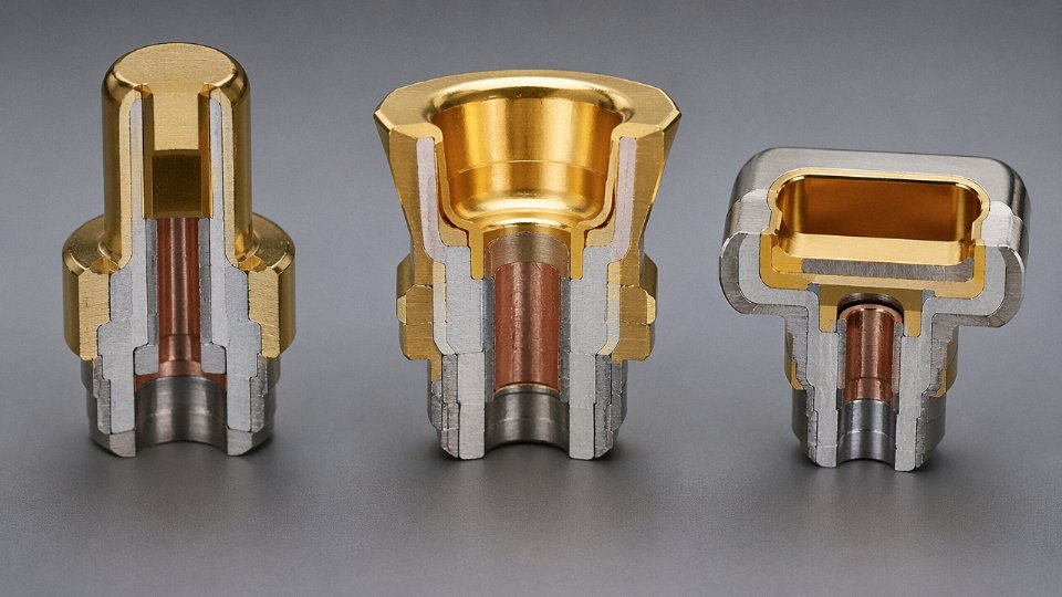
Tin plating at 1–3 µm is the default for indoor, relatively stable environments — control panels, building automation, low-vibration machinery. It handles service up to roughly 120 °C and is inexpensive to apply. The problem surfaces in vibrating environments: fretting corrosion. Even micro-motion at 10–100 µm amplitude — the kind that comes from a diesel engine running nearby, or a rail car rolling over a track joint — abrades tin plating. The debris is tin oxide, which is an insulator. Contact resistance climbs, the circuit becomes intermittent, and diagnostics chase a ghost. For those environments, the fix is either specifying increased contact normal force (which puts the requirement back on the base metal) or upgrading to gold flash over nickel underplate. The nickel barrier layer matters: without it, gold diffuses into the base metal and you lose the benefit.
Silver plating (3–5 µm) is excellent for RF contacts and high-current busbars where conductivity and surface area matter. The known weakness is sulfur-bearing atmospheres — paper mills, wastewater treatment, certain chemical plants. Silver sulfide tarnish is resistive. If your installation site has any sulfur presence, either seal the connector properly or consider gold.
Gold plating at 0.1–1.27 µm is non-negotiable for low-level signal contacts operating below 100 mV dry circuit. At those voltage levels, even a thin oxide film breaks the circuit. Gold doesn’t oxidize. The thickness depends on cycle life requirements — 0.1–0.2 µm is adequate for moderate cycles, 1.27 µm is called out for demanding military and aerospace specs.
Gold-plated contacts are necessary for reliable dry-circuit signal connections below 100 mV, where oxide films on tin or silver surfaces would disrupt conductivity.True
At voltages below approximately 100 mV, there is insufficient electrical energy to break down resistive oxide films on tin or silver surfaces. Gold resists oxide formation, maintaining stable, low contact resistance — this is established in IEC 61984 and widely documented in connector reliability engineering literature.
Housing and Sealing Materials: Match the Environment, Not the Datasheet
PA66-GF30 (glass-filled polyamide, 30% glass) is the standard housing material for general industrial connectors — good rigidity, tracks to roughly 130 °C continuous, reasonable chemical resistance, and it processes well in injection molding. For under-hood automotive or anywhere continuous service temperatures exceed that, polyphenylene sulfide (PPS) is the step up. PPS handles around 220 °C continuously and resists most automotive fluids without swelling or cracking. It’s more brittle than PA66, which occasionally shows up as chipped locking latches if someone is rough with it during assembly.
Die-cast zinc alloy shells earn their place in industrial automation not because of temperature ratings but because of EMC shielding continuity. The shell needs to make low-impedance contact with the cable braid and the panel cutout simultaneously — a plastic housing, even with a metallized coating, rarely matches the consistency of a zinc die-casting. Stainless steel housings appear in subsea connectors and food-processing equipment, where the combination of corrosive wash-down chemistry, moisture, and mechanical abuse rules out most other options.
Sealing compounds are where I see the most specification errors in practice. NBR (nitrile) O-rings are fine for mineral oil and water service, but swap in an EPDM compound for steam or ozone environments. Silicone covers a wide range — roughly −60 °C to +200 °C — and is the safe default for outdoor temperature-cycling applications. Aerospace hydraulic fluid and jet fuel exposure requires fluorosilicone; standard silicone swells badly in those media.
Cable-to-Connector Interface: Where the IP Rating Actually Lives
One detail that gets missed in system integration: the IP seal at the cable entry point depends entirely on the strain-relief boot clamping down on the jacket OD within a defined tolerance band. If the cable jacket OD runs toward the low end of its manufacturing tolerance and the strain-relief clamp ID is at the high end, the boot never forms a proper seal, and your IP67 rating exists only on paper. Matching jacket OD tolerance to clamp ID at the design stage — and verifying it on incoming inspection — is unglamorous work, but it’s the difference between a sealed installation and one that ingresses water at the first rain event. Specifying cable from a manufacturer who holds tight jacket OD tolerances makes this problem largely go away.
Industry-Specific Connector Deployment: Power, Data, Marine, and Renewable Energy Applications
The three connector families don’t map cleanly onto “low voltage = terminal blocks, high voltage = splices” — reality is messier than that. Each industry vertical has evolved its own preferred connector ecosystem driven by a specific mix of ingress protection requirements, current density, mating cycle frequency, maintenance access, and certification body demands. Knowing which family dominates your sector saves real time during the design phase.
Power Distribution and Switchgear
Terminal blocks own 0.4 kV through 35 kV panel wiring, full stop. In medium-voltage switchgear cubicles you’ll typically see DIN-rail screw or spring-cage blocks handling control and instrumentation circuits, while busbar-mounted bolted connectors take feeder-level currents above 630 A — those connections are torqued to manufacturer spec with a calibrated wrench, not hand-tightened, because under-torque at that current density means intermittent resistance and eventually a thermal event.
For underground utility networks, the relevant accessory is the heat-shrink or cold-shrink molded joint kit for medium-voltage cable splices. IEC 60502-4 governs these accessories; it sets requirements for the mechanical, electrical, and environmental performance of joints and terminations on cables rated 1 kV to 30 kV. Installers who skip the mandated post-installation test on a medium-voltage joint tend to find out about it eighteen months later during a wet season.
Industrial Automation and Robotics
M8 and M12 circular connectors per IEC 61076-2-101 are essentially the universal language of factory-floor sensor wiring at this point. PROFINET, IO-Link, Ethernet/IP — all of them have standardized on M12 D-coded or X-coded variants. The contact resistance on a quality M12 sits in the 5–15 mΩ range; a corroded or counterfeit substitute can push that above 40 mΩ and cause intermittent data dropouts that production teams often misdiagnose as PLC firmware issues for weeks before tracing it to the connector.
Servo drive harnesses are a different animal. They use heavier circular or hybrid rectangular connectors with integrated EMC shield termination — the shield must terminate to the connector backshell, not float, otherwise radiated emissions eat into encoder feedback signal integrity.
Marine and Offshore
Marine installations operate under IEC 60092-352 for cable construction, and the connectors that interface with those cables need IP68 or IP69K ratings as a minimum in exposed topside locations. Wet-mate subsea connectors — the kind an ROV can plug and unplug at working depths down to roughly 3,000 m — use titanium or acetal housings because standard aluminum corrodes and standard thermoplastics creep under hydrostatic pressure. Class society survey (Lloyd’s, DNV, BV) requires documented traceability between the cable and its termination accessories. Jinda’s marine-approved cable range is built to those cable standards, and specifying the correct entry gland OD from the cable datasheet up front prevents the frustrating situation where a surveyor rejects a termination because the cable outer diameter was borderline for the connector strain relief.
Renewable Energy — Solar PV and Wind
MC4 and Stäubli MC4-compatible connectors are the global PV standard. IEC 62852 sets the requirements for DC-side connectors rated to 1,500 V DC, including mechanical retention force and insulation resistance thresholds.
MC4-compatible connectors from different manufacturers are always interchangeable in the fieldFalse
IEC 62852 permits dimensional compatibility testing, but several independent laboratory studies and installer field reports have documented elevated contact resistance and reduced retention force when mixing brands. Most connector manufacturers and IEC guidance explicitly recommend using matched-brand pairs throughout a string.
UV-stabilized housing matters here more than most buyers appreciate — 25 years of UV exposure in a desert or rooftop installation will embrittle a standard PA66 housing to the point of cracking. Silver-plated contacts resist the electrochemical corrosion that bare copper contacts develop under cyclic thermal loading.
Wind turbine nacelles introduce a different connector stress: continuous high-flex cycling on trailing cables handling yaw and pitch motion. The cables need a torsion-rated construction, and the circular multi-pole connectors at each end need strain relief designed for that motion rather than static pull-out. Jinda supplies flexible wind-turbine cables engineered to match the entry OD specifications on common nacelle connector families. At the tower base, slip-ring assemblies replace discrete connectors for the continuously rotating power and data circuits — you can’t use a standard connector there without twisting the cable to destruction.
Rail and Transportation
EN 45545 restricts housing materials based on hazard levels HL1 through HL3 — a connector housing that passes UL 94 V-0 may still fail EN 45545 HL3 smoke toxicity requirements. Vibration profiles per IEC 61373 Category 1 Class B are punishing enough that spring-cage terminal blocks significantly outperform screw-cage in long-term retention. Brake and door-control circuits in rail vehicles almost always require redundant connection paths — two separate terminal points per conductor is common, not belt-and-suspenders over-engineering but a genuine safety architecture requirement.
Procurement Quality Checklist: Eight Verification Steps Before Approving a Connector Order
Getting the specification right is one thing. Getting the right physical product delivered, certified, and ready to install is a different problem entirely — and it’s where projects quietly bleed money.
Step 1 — Verify Connector-to-Cable Compatibility
Start with the dimensional drawing, not the catalog page. Confirm the connector’s accepted conductor cross-section range against your actual cable, and check stranding class explicitly: IEC 60228 runs from Class 1 (solid) through Class 6 (extra-flexible, fine-stranded), and a connector crimp barrel dimensioned for Class 5 will give unreliable termination on Class 2 solid wire of nominally the same cross-section. The strain relief is equally important — jacket OD tolerance on armored or multi-core cables can vary ±0.5–1.5 mm depending on manufacturer, and a strain relief that doesn’t clamp properly transfers flex stress directly onto the contact crimp. Request the manufacturer’s dimensional PDF, not a marketing sheet.
Step 2 — Cross-Check Ratings Under Actual Operating Conditions
Nameplate current ratings are almost always stated at 40 °C ambient. Above that, IEC 61984 requires derating — roughly 5–15% per 10 °C increment depending on the connector series, though check the published derating table for your specific type rather than applying a generic rule. Multi-pole connectors carrying current on most or all contacts simultaneously generate additive heat; a 32-pole connector fully loaded runs meaningfully hotter than its single-pole test configuration. For installations above 2,000 m altitude, dielectric strength degrades due to reduced air density — relevant for high-voltage connector types and worth an explicit conversation with the supplier if your project is in highland regions.
Step 3 — Confirm Certification Scope Precisely
A CE logo on a datasheet means almost nothing without the Declaration of Conformity behind it, and the DoC must cite a specific harmonized standard — EN 61984 for industrial connectors, for example — not a vague reference to “applicable directives.” UL listings are series-specific and wire-range-specific; a UL listing for 12–22 AWG does not cover 10 AWG, full stop. Ask for the current certificate with issue date. Certificates lapse, get withdrawn, or cover only a subset of the product range.
A CE Declaration of Conformity must reference a specific harmonized standard to be valid under EU machinery and low-voltage directives.True
Under EU directive requirements, a DoC must identify the specific harmonized standards applied. A generic CE mark without a referenced standard provides no verified compliance and may fail customs or third-party audit scrutiny.
Step 4 — Request Material Declaration and RoHS/REACH Compliance
If the product enters EU, UK, or California markets, housing polymers, contact plating, and any solder or flux residues need to be clear of SVHC (Substances of Very High Concern) under the current REACH candidate list — which updates periodically, so a declaration from three years ago may already be outdated. Nickel flash under gold plating is generally fine; certain cadmium-containing platings are not. Get a current full material declaration, not just a checkbox on a supplier questionnaire.
Step 5 — Inspect Test Reports for Contact Resistance and Withstand Voltage
Contact resistance measured per IEC 60512-2-1 should fall within the range appropriate for your connector type — signal-grade contacts typically run 5–20 mΩ; heavy industrial power contacts may run up to 50 mΩ new and should be evaluated against the system’s thermal budget. Dielectric withstand per IEC 60512-4-1 confirms insulation integrity. Critically: check whether the report reflects first-article testing on a pre-production sample or ongoing production batch testing. First-article reports look authoritative but tell you nothing about production consistency.

Step 6 — Evaluate Mating and Extraction Force Data
This gets skipped more often than it should. Too-low extraction force — common in off-spec or worn tooling production — means the connector releases under vibration or cable pull. Too-high mating force causes installers to use improvised tools, which cracks connector bodies or bends contacts. Acceptable force ranges vary by connector series standard, so ask the supplier for their production test spec, not just a nominal figure.
Step 7 — Assess Supply Chain Risk for Long-Duration Projects
A 10-year infrastructure project that depends on a single-source connector from one factory in one country is carrying quiet, compounding risk. Ask the supplier whether equivalent second-source connectors exist with compatible dimensional and electrical specs. If not, negotiate a long-term supply agreement that defines lead times, safety stock levels, and price escalation terms — ideally before the project is past the design freeze point, when your leverage is still real.
Step 8 — Align Connector and Cable Procurement
Ordering cables and connectors from separately sourced suppliers is standard practice, but it creates an interface gap: jacket OD variance, conductor stranding, and insulation wall thickness all affect termination quality, and no one supplier owns the problem when something doesn’t fit. Jinda supplies cable-and-termination bundles with matched dimensional and electrical specifications across the same quality management system, which reduces system integrator engineering time and eliminates the common scenario where connectors arrive on site and simply don’t fit the cable batch that was delivered a week earlier.
Frequently Asked Questions About Cable Connector Types
What is the most common type of cable connector used in industrial settings?
Honestly, this depends on where in the system you’re standing. On the machine floor — at sensors, actuators, and valve manifolds — M12 circular connectors are almost ubiquitous in modern automation. They’re compact, they handle the vibration, and most field devices have M12 ports as standard. Walk back to the control cabinet, though, and you’ll find screw-terminal blocks dominating the din rail, terminating the same signals that M12s picked up out in the field. Both connector families coexist in a single system, each solving a different connection problem. Trying to replace one with the other is usually impractical — a screw terminal block doesn’t belong in a wet, vibrating conduit run, and running individual M12 pigtails into a 200-point PLC cabinet would be a maintenance nightmare.
Can I use a plug-and-socket connector instead of a butt splice for a permanent outdoor installation?
Technically yes, provided the connector is rated for the exposure — IP68 mated, UV-stabilized housing, and suitable for direct burial if that’s the application. The real question is whether you need the disconnectability. For a permanent run that will never intentionally be unmated, sealed butt splice connectors cost significantly less, eliminate the risk of accidental disconnection (which in outdoor power circuits can mean arc flash or ground fault), and create a lower-profile joint that fills cleanly inside conduit. Plug-and-socket connectors make sense outdoors when you genuinely need field-removable equipment — a roadside lighting fixture, a shoreside power pedestal, a relocatable pump skid. For direct-buried cable splices, the sealed splice is almost always the right answer.
What connector type is required for solar PV DC wiring?
IEC 62852 governs PV connector requirements. In practice this means MC4-style connectors rated for the system’s maximum open-circuit voltage — which on modern utility-scale strings can reach 1,500 V DC — and the string’s short-circuit current. One point that gets ignored surprisingly often: mixing connector brands is prohibited under most installation codes and by IEC 62852 itself. An MC4-compatible connector from a different manufacturer may mate physically but can produce higher contact resistance, accelerated wear, and potentially unsafe contact retention force. This isn’t a theoretical concern — field inspectors on larger PV installations specifically look for mixed-brand mating pairs and will flag them. Use matched sets from the same qualified product family throughout.
How do I know if a terminal block is rated for aluminum conductors?
Look at the body of the terminal block itself for an “AL” or “CU/AL” marking. Aluminum-rated blocks incorporate anti-oxidant compound channels, larger contact surface areas to compensate for aluminum’s lower conductivity, and in many designs, a tin-plated or bi-metallic clamping mechanism that resists the galvanic corrosion that destroys standard copper-only terminals within months when aluminum conductors are inserted. Most standard DIN-rail screw terminal blocks are copper conductor only, regardless of what a distributor’s datasheet implies by omission. If the marking isn’t clearly visible on the block body, assume copper-only.
Inserting aluminum conductors into copper-only terminal blocks without anti-oxidant compound causes progressive oxidation that increases contact resistance, leading to overheating failures within 12–36 months of service.True
Aluminum oxide forms rapidly at the contact interface when aluminum and copper are in contact without proper treatment; the oxide layer is resistive and grows over time, consistent with IEC and NEC guidance on aluminum termination requirements.
What is the difference between IP67 and IP68 for connectors?
IP67 covers temporary immersion — up to 1 m depth for 30 minutes. IP68 covers continuous immersion at a depth and duration specified by the manufacturer, commonly ranging from 1 m to 10 m depending on the product. The critical detail that gets overlooked in procurement: the rating applies to the mated connector pair, tested assembled. A housing rated IP68 on its own tells you almost nothing about how the joint performs when an IP67 mating plug is inserted. Always verify that the tested IP rating covers the mated condition, and check the manufacturer’s test depth figure, not just the “68” designation, because that number alone doesn’t specify depth.
How does connector choice affect overall cable system warranty?
Using a connector outside the cable manufacturer’s approved accessory list — or one not tested for compatibility with the cable’s insulation system, jacket compound, or voltage rating — can void the cable system warranty entirely. This is especially relevant in medium-voltage power cable installations and marine cable systems where third-party termination kits are sometimes substituted on cost grounds. Jinda provides a recommended connector compatibility guide with each cable product family, specifying which connector types, termination methods, and accessory brands have been validated against the cable’s design. Procurement teams should request this documentation at the point of cable specification, not after the cable is already on site.
What causes a connector to overheat in service?
There are four main causes, and in practice they often compound each other. First, under-rated current selection — the connector’s ampacity was sized for nameplate current without accounting for actual load growth or parallel circuit imbalance. Second, high contact resistance from improper crimping or oxidized contact surfaces, which turns the connection point into a resistive heater; contact resistance in a degraded crimp can climb well above the 50 mΩ upper end of the acceptable range discussed earlier in this article. Third, loose screw terminals — a torque that was correct at installation backs off slightly over thermal cycling, increasing resistance progressively. Fourth, derating ignorance in high-ambient environments: a connector rated at 16 A at 25°C may only safely carry 11–13 A in a 55°C enclosure, depending on the derating curve, and that curve is rarely consulted during panel design. Any one of these is enough to cause premature failure; two or three together usually mean a connector that fails within the first operating season.
How Jinda Supports Global Connector-Cable Integration Projects from Specification to Delivery
Most connector problems on large projects don’t originate on the factory floor. They originate six months earlier, in a cable schedule that nobody cross-checked against the connector interface drawing. By the time a shipment arrives at a substation in Saudi Arabia or a rail depot in Southeast Asia and the jacket OD is 0.4 mm over the strain-relief bore, the contractor is looking at re-termination labor, schedule compression, and a change order that costs far more than a proper pre-production review would have.
Engineering Consultation Before a Single Meter Is Produced
Jinda’s technical team works through customer cable schedules at the specification stage — not as a formality, but as a deliberate fault-finding exercise. That means checking conductor class against connector contact geometry, verifying jacket OD tolerances fit within the customer’s specified strain-relief range, and flagging certification gaps before production runs begin. For a 500 km transmission project or a multi-year rail supply agreement, catching a dimensional mismatch at this stage typically eliminates what would otherwise become a costly change order mid-contract. In practice, the mismatches that surface most often are jacket material incompatibilities with connector sealing compounds, and conductor stranding classes that don’t match the contact’s crimp barrel range.
This kind of front-end review is genuinely unusual among volume cable suppliers. Most will confirm to a drawing; fewer will argue with it when something is wrong.
Production Scale That Holds Across Long Contracts
Five manufacturing bases across China, roughly 470,000 m² of production space, and over 1,000 employees give Jinda the capacity to sustain large-volume orders across multiple production runs without the quality drift that plagues smaller manufacturers when they stretch resources. For energy and rail procurement teams managing multi-year supply agreements, consistency from batch one to batch forty matters at least as much as the unit price. Conductor resistance, insulation wall thickness, jacket OD — these need to stay within tolerance across every run, not just the qualification samples.
Jinda holds IEC, CE, UL, and CCC certifications across its cable product lines.True
These certifications are standard requirements for export-oriented cable manufacturers serving infrastructure, energy, and industrial customers across Europe, North America, and China's domestic market. Jinda's product lines have been tested and approved under these schemes, which customers can verify through certification documentation provided at the quotation stage.
Certifications That Simplify System-Level Approval
Holding IEC, CE, UL, CCC, and other market-specific certifications means that when a customer submits a connector-cable assembly for system approval, the cable side of the interface already carries pre-tested documentation. That removes one approval loop — sometimes a significant one, depending on the authority having jurisdiction. For customers in markets with stringent import certification requirements, receiving cables with complete test reports in hand compresses the project timeline noticeably.
Custom Jacket and Conductor Specifications for OEM Assemblies
OEM customers designing proprietary connector-cable assemblies often need cable geometry held to tighter tolerances than standard commercial product. Jinda can specify jacket OD within narrow ranges, select conductor stranding class to match a specific crimp contact, and choose outer layer materials — whether that’s a chemical-resistant TPU or a low-smoke halogen-free compound — to meet the connector’s strain-relief and environmental sealing requirements. This matters most for customers who are finalizing a connector design in parallel with the cable spec, where both sides of the interface are still moving.
Logistics and Support Across Time Zones
Serving customers in more than 50 countries means Jinda has established freight routes, export documentation workflows, and regional logistics experience that reduce the administrative burden on procurement teams managing complex project timelines. Technical support available across time zones is genuinely useful for customers in Africa, the Middle East, or Southeast Asia who are dealing with a site question at a time when most European or North American suppliers are offline.
If you have a cable and connector specification sheet in hand — even a preliminary one — Jinda’s engineering team will review it at no obligation and identify any interface concerns before they become procurement problems. That’s a straightforward offer, and it’s where most successful long-term supply relationships start.