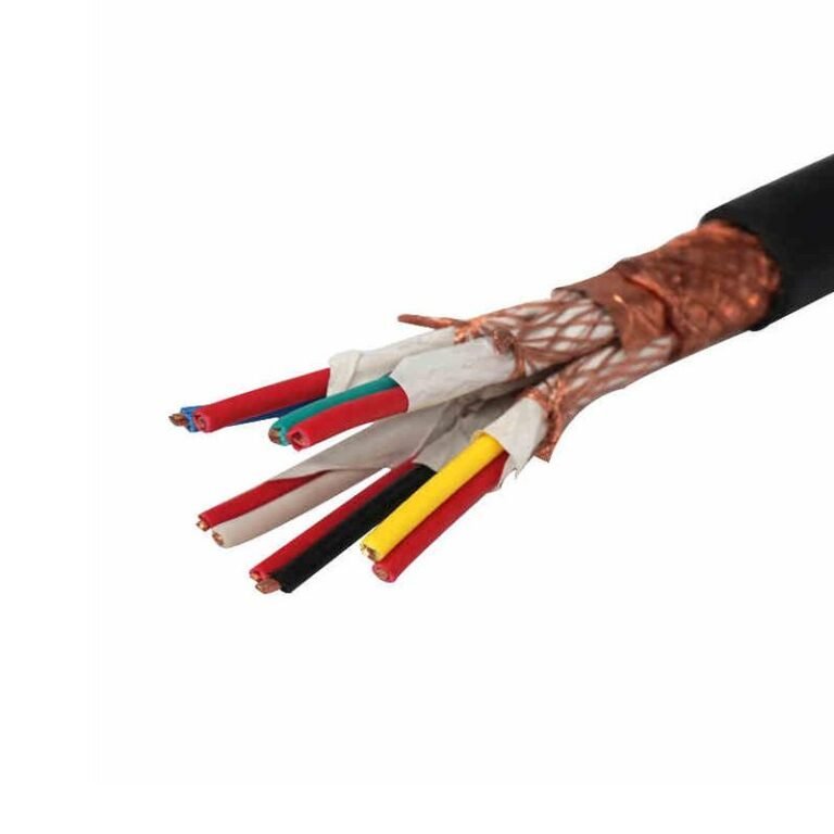
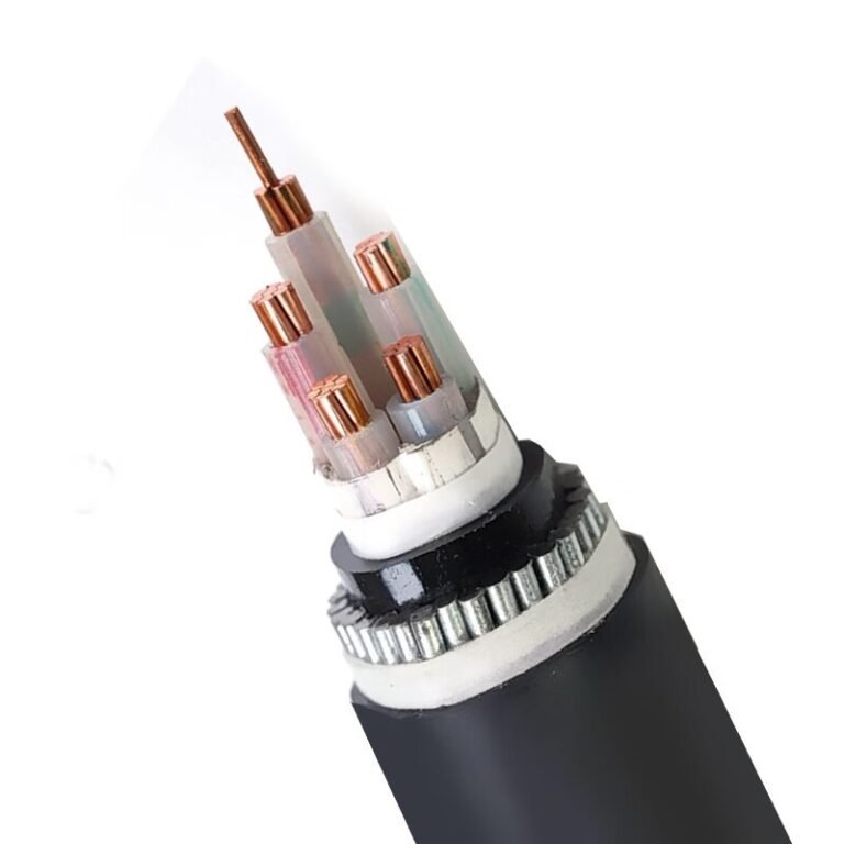
Portable mining equipment, trailing cable systems, and heavy-duty flexible power feeds all share one brutal operating reality: the cable gets dragged, crushed, soaked, and exposed to fuel — and when it fails mid-shift, you’re not just looking at a replacement cost, you’re looking at unplanned downtime that on a continuous mining operation can run into tens of thousands of dollars per hour. Most cable failures in these environments trace back to the same root cause — specifying a general-purpose flexible cable where a purpose-built one was needed.
A Type 4 power cable is a heavy-duty flexible power cable designed for continuous trailing and reeling service in mining, quarrying, and industrial environments. It is typically rated to 600 V or 1000 V AC, uses oil-resistant and flame-retardant CPE or EPR insulation, and is built to flex repeatedly without conductor fatigue — distinguishing it from fixed-wiring cables that physically cannot survive the mechanical abuse of mobile equipment.
What makes the Type 4 classification genuinely useful — and what most procurement specs still get wrong — is that the designation sits at the intersection of electrical rating, mechanical construction, and environmental resistance in a way that a simple voltage or temperature rating never captures on its own. The conductor sizing alone spans a wide range, from roughly 16 mm² up to 500 mm² depending on load and application, and the construction choices behind that range have real consequences for service life, reeling drum geometry, and cold-weather flexibility down to −40 °C.
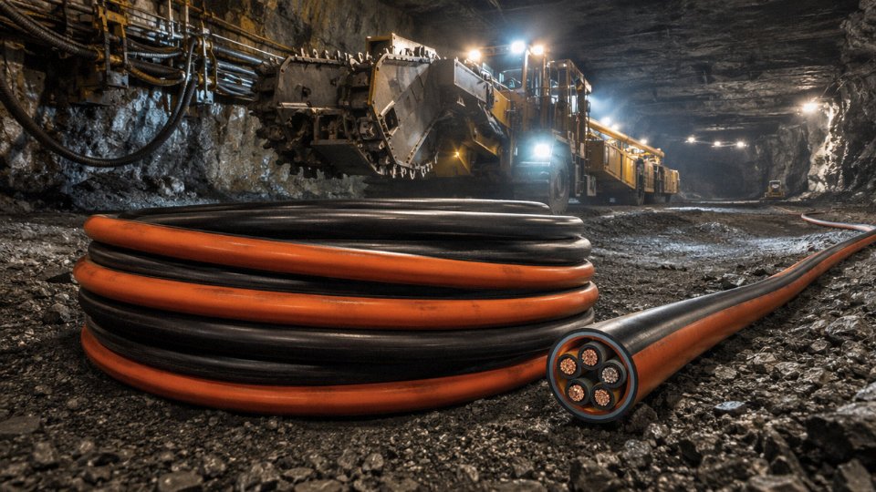
Type 4 Cable Construction: Layer-by-Layer Anatomy and Material Choices
Understanding what’s inside a Type 4 cable is what separates a well-written purchase specification from one that gets you a product that fails in six months. Each layer does a specific job, and the material choices at each layer interact — getting one wrong undermines the others.
Power Conductors
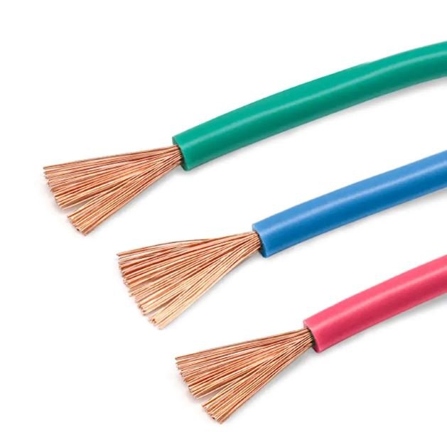
The conductors in a Type 4 cable are bare or tinned annealed copper, drawn down to individual wire diameters typically in the 0.2–0.5 mm range and then rope-laid into a high-strand-count assembly. IEC 60228 Class 5 or Class 6 (roughly equivalent to ASTM B172 Class G or Class H in North American terms) is the standard here. For a 95 mm² conductor you might be looking at 400–600 individual strands, give or take depending on the manufacturer’s die sequence.
Why does this matter operationally? A cable dragged across a mine floor, coiled and uncoiled on a reel dozens of times a week, experiences cumulative fatigue at the conductor level. A solid or coarse-stranded conductor work-hardens and fractures at the termination point — usually within a few hundred flex cycles. Fine-wire rope-lay construction pushes that to tens of thousands of cycles under realistic service conditions. In practice, any Type 4 specification that doesn’t call out minimum strand count or IEC 60228 class by name is leaving the door open for a supplier to substitute something unsuitable.
Insulation Materials
EPR (ethylene propylene rubber) dominates Type 4 insulation for good reasons. Its dielectric constant stays stable across the operating temperature range, it handles moisture without significant degradation of electrical properties, and it tolerates the thermal cycling that happens when a cable feeds a high-inertia load like a dragline or continuous miner. Continuous operating temperature is typically rated to 90°C, with short-circuit withstand up to around 250°C — numbers that matter when sizing protection devices.
CPE (chlorinated polyethylene) is used as insulation in some cost-optimised versions, mostly where the thermal and dielectric demands are moderate. It’s cheaper to compound and easier to extrude, but its dielectric loss tangent is noticeably higher than EPR at elevated temperatures, which becomes relevant in longer runs or higher-frequency applications.
XLPE variants appear in certain IEC 60502-1 interpretations of Type 4-equivalent cables, particularly in markets outside North America. The cross-linking improves thermal performance but XLPE is stiffer than EPR at low temperatures — at -40°C a thick-walled XLPE insulated cable can crack during installation if it hasn’t been properly conditioned, which is a real field problem in northern Canadian or Siberian open-cut operations.
EPR insulation maintains superior dielectric performance compared to CPE at elevated operating temperaturesTrue
EPR's non-polar molecular structure gives it a lower and more stable dielectric loss tangent than CPE across a wide temperature range, which is well-documented in IEEE and IEC insulation testing data and consistent with compound manufacturer technical datasheets.
Ground Conductors and the Pilot Core
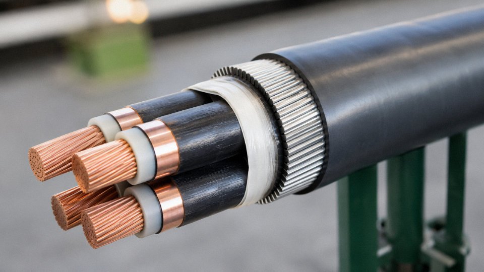
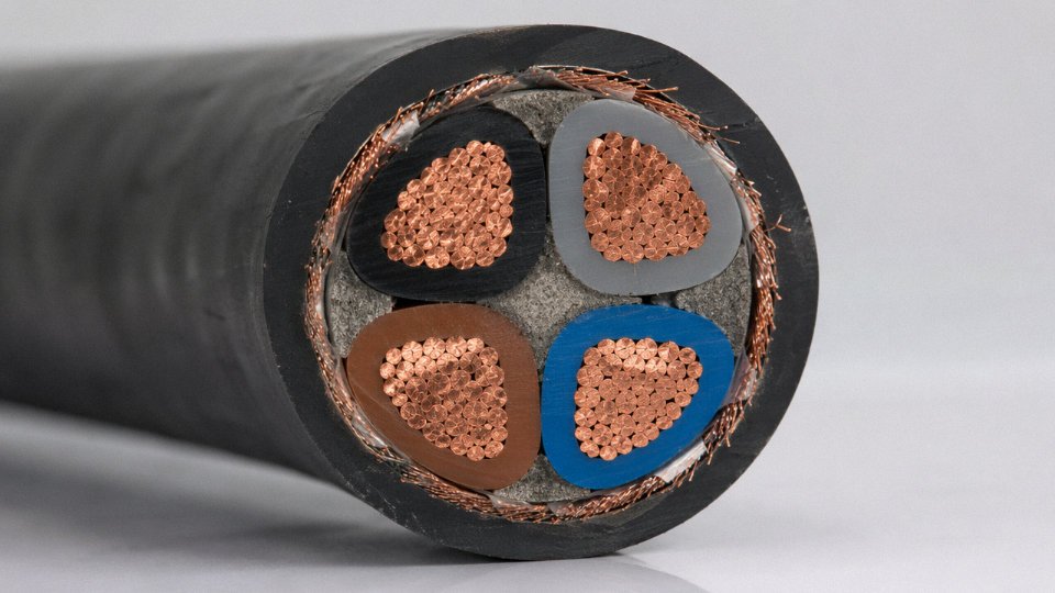
MSHA-compliant Type 4 cables carry ground conductors sized equal to or proportional to the phase conductors — not a token reduced-area ground like you’d find in a general-purpose flexible cord. A typical three-phase Type 4 cable will have three phase conductors and either one full-size ground or multiple grounds geometrically distributed around the core. The geometric placement isn’t arbitrary: symmetrical ground arrangement keeps the cable balanced during flexing and prevents one conductor from migrating toward the outside of the bend radius over time.
The ground-check (pilot) conductor is a small-cross-section core — often 1.5–6 mm² — used by the mining machine’s protective relay system to continuously monitor ground circuit continuity while the machine is operating. If ground continuity is lost, the relay trips before a fault can develop into a personnel hazard. This is a safety-critical feature that some general industrial flexible cables simply don’t include. Its absence is a quick disqualifier when evaluating alternative products.
Fillers, Binders, and Separator Tapes
The spaces between conductors are filled with a rubber or thermoplastic compound — sometimes extruded, sometimes pre-formed strips — that keeps the cable’s cross-section round under flexing load. A cable that goes oval under repeated bending concentrates stress at the bend point and fails prematurely. Separator tapes, typically non-hygroscopic polyester or similar materials, wrap individual conductors or the assembled core to prevent insulation compounds from bonding to one another or to the jacket during vulcanisation. This matters at termination: if the jacket bonds to the insulation, field stripping becomes difficult and there’s real risk of nicking the insulation with a knife. A well-designed Type 4 cable should strip cleanly with a ringing cut and a pull.
Outer Jacket
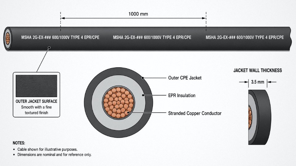
The jacket is usually CPE or CSPE (a Hypalon-type compound), applied by pressure extrusion over the assembled core. CSPE has better ozone and UV resistance than plain CPE, which matters for surface applications or cables stored outdoors between shifts. Both compounds provide the oil resistance needed around hydraulic equipment and the flame retardancy required under IEEE 1202 or IEC 60332-3. Jacket wall thickness scales with conductor size — roughly 2.5–4.5 mm for cables in the 35–240 mm² range, though this varies by standard and manufacturer.
Abrasion resistance is the property that gets cables killed fastest in underground coal applications. A nominally compliant jacket compound that’s been reformulated to reduce compound cost can lose 30–40% of its abrasion resistance without visibly failing a tensile test. Requesting Shore A hardness data and Taber abrasion test results as part of your supplier qualification process is worth the effort.
Representative Construction Data
| Conductor Size | Voltage Rating | Insulation Thickness (approx.) | Jacket Thickness (approx.) | Overall Diameter (approx.) | Weight (approx.) |
|---|---|---|---|---|---|
| 16 mm² (AWG 6) | 600/1000V | 1.6–2.0 mm | 2.5–3.0 mm | 28–34 mm | 1.8–2.4 kg/m |
| 50 mm² (1/0 AWG) | 600/1000V | 2.0–2.4 mm | 3.0–3.5 mm | 42–50 mm | 4.5–5.5 kg/m |
| 120 mm² (~250 kcmil) | 600/1000V | 2.4–2.8 mm | 3.5–4.0 mm | 60–72 mm | 9.5–12 kg/m |
| 240 mm² (~500 kcmil) | 600/1000V | 2.8–3.2 mm | 4.0–4.5 mm | 80–95 mm | 18–23 kg/m |
Figures shown are for a 3-phase + ground configuration with EPR insulation and CPE jacket. Actual dimensions depend on strand class, number of ground conductors, filler volume, and the manufacturer’s tooling. Always verify against the supplier’s dimensional drawing before committing to conduit sizing or reel specifications.
Applicable Standards and Approvals: MSHA, UL, IEC, and Regional Certifications
Getting the certification wrong on a trailing cable order isn’t a paperwork headache — it’s a job-site shutdown. Inspectors pull cables, mines halt production, and the cost of re-procurement under time pressure is never pretty. So this section maps the actual regulatory landscape, jurisdiction by jurisdiction, in enough detail that a procurement manager can build a specification that survives an audit.
MSHA Approval: The Benchmark for U.S. Mining Applications
In the United States, any trailing cable used in underground coal mining must carry MSHA approval under 30 CFR Part 18 (for underground use) or Part 19 (surface, though requirements overlap substantially). MSHA tests are not trivial — they include flame propagation tests, AC voltage withstand, insulation resistance under wet conditions, and physical abuse testing of the jacket and sheath. The approval number, typically formatted as MSHA 2G-EX-###, must be printed legibly on the cable’s outer jacket at regular intervals, usually every meter or so. If you can’t read the approval number off the reel you’re about to deploy, that’s a red flag worth stopping for.
One thing procurement teams sometimes misunderstand: MSHA approval is cable-specific. A manufacturer can’t take an MSHA-approved 3/0 AWG design and claim the approval covers their 4/0 AWG variant unless that conductor size was explicitly tested and listed. Verify the approval against the exact construction — conductor size, voltage rating, jacket compound — not just the brand or product family name.
UL Listing and Its Relationship to MSHA
UL listing under UL 2275 (cables for use in hazardous locations) addresses a different slice of the compliance picture. UL 2275 focuses on electrical performance, insulation integrity, and suitability for classified hazardous environments — think oil-and-gas surface facilities or industrial plants where flammable vapors are present. MSHA approval and UL listing are complementary, not substitutes for each other. A cable can hold both, and for a contractor working across both mining and industrial petrochemical sites, specifying both is often the right call. But a UL-listed cable without MSHA approval cannot legally be run as a trailing cable in a U.S. underground mine, full stop.
UL listing under UL 2275 is a direct substitute for MSHA approval in U.S. underground coal mining applications.False
MSHA approval under 30 CFR Part 18 is a separate, mandatory federal certification for underground mining trailing cables. UL 2275 addresses hazardous-location suitability for different application categories. The two certifications serve different regulatory frameworks and are not interchangeable.
IEC Frameworks: 60502-1 and 60245
Outside North America, the relevant IEC standards are IEC 60502-1 (power cables with extruded insulation, up to 1 kV) and IEC 60245 (rubber-insulated cables, which covers the flexible, mining-oriented constructions more closely aligned with what engineers know as Type 4). A cable built to IEC 60245 with CPE or EPR insulation, appropriate ground conductors, and a rated voltage of 0.6/1 kV is functionally a Type 4 equivalent — the designation just won’t appear on the print. Buyers sourcing for projects in Europe, Southeast Asia, or the Middle East should specify against these IEC standards directly, and ask suppliers to confirm compliance with the specific parts (IEC 60245-4 or IEC 60245-6 are the most commonly relevant).
Regional Standards Worth Knowing
CSA (Canada): CSA C22.2 No. 96 covers portable power cables and aligns closely with Type 4 construction requirements for mining. Canadian projects typically require CSA certification alongside or instead of MSHA.
AS/NZS 2802 (Australia and New Zealand): This is the primary standard for mining flexible cables in both countries. It specifies constructional requirements, flame performance, and voltage ratings that map well onto Type 4 parameters, though the test methods differ from IEEE 1202.
SANS (South Africa): South African mines — particularly the deep-level gold and platinum operations — reference SANS standards derived partly from IEC frameworks. SANS 1507-3 and related parts cover flexible cables for mining applications. Procurement for South African projects should confirm which SANS parts apply to the specific mine classification.
Compliance Checklist: Minimum Documentation to Request
Before issuing a purchase order, any serious buyer should be holding the following:
| Item | What to Verify |
|---|---|
| Voltage rating | Matches site requirement — 600V or 1000V; confirm AC or DC rating |
| Flame test standard | IEEE 1202 (North America) or IEC 60332-3 (IEC markets); not interchangeable |
| Temperature marking | Continuous rating (typically –40°C to +90°C), visible on jacket print |
| Ground conductor sizing | Meets application standard — MSHA specifies sizing relative to phase conductors |
| Jacket compound ID | CPE vs. EPR vs. EPDM — each has different oil, ozone, and UV resistance profiles |
| Third-party test reports | SGS, Bureau Veritas, or Intertek reports tied to the specific cable construction |
That last point matters more than many buyers realize. A manufacturer’s own test data is a starting point, not a final answer. Third-party test reports from accredited labs — especially for export projects where the cable will be installed in a jurisdiction where the buyer has no local supplier relationship — provide documentation that holds up if something goes wrong later.
Jinda holds export certification documentation covering IEC 60502-1, IEC 60245, and other applicable frameworks, supported by third-party testing through recognized international labs. For projects requiring MSHA or CSA compliance, the appropriate regional certification path should be confirmed early in the procurement cycle, since testing lead times can add several weeks to a delivery schedule if not planned for.
Electrical Ratings, Voltage Classes, and Performance Parameters
Type 4 cables aren’t a one-size product, and the voltage class you specify will determine nearly everything downstream — insulation wall thickness, shield design, and how your ground-fault relay behaves at the end of a 300-meter trailing run.
Voltage Classes: North American vs. IEC
In MSHA-governed North American mining, the two dominant ratings are 600 V (rms) and 2000 V (rms). The 600 V class covers most surface auxiliary equipment and lower-voltage feeder circuits; 2000 V is the workhorse for trailing cables on draglines, shovels, and longwall systems where the mining distribution voltage sits at 1000–1500 V line-to-line. If you spec the wrong class — say, 600 V cable on a 1000 V system — the insulation wall is undersized for the overvoltage transients that inductive switching routinely generates in dragline service. You’ll see premature insulation breakdown within a season, sometimes faster on reeled drums where mechanical flexing compounds the damage.
For IEC-governed markets, the standard rating is 0.6/1 kV (U₀/U), where U₀ is the conductor-to-ground voltage and U is the conductor-to-conductor voltage. This maps closely to the 2000 V MSHA class in terms of insulation design margin. Higher-voltage trailing applications — particularly in Australian and South African open-cut mining, and in some European underground hard-rock operations — use 3.3 kV and 6.6 kV versions built to IEC 60502-1 or site-specific utility standards. At 6.6 kV, the cable construction changes substantially: thicker insulation walls, stress-control layers, and metallic screens that carry fault current back to the source. These aren’t catalogue items you pull off a shelf; lead times of 8–14 weeks are typical.
A Type 4 cable rated 600 V (MSHA) is not interchangeable with a 0.6/1 kV IEC-rated cable — voltage class definitions, insulation wall thickness requirements, and test voltage protocols differ between the two standards.True
MSHA defines cable ratings by peak service voltage and applies its own test voltage protocols under 30 CFR Part 18/75, while IEC 60502-1 specifies U₀/U ratings tested by AC voltage withstand and impulse tests. The numerical voltage values can appear similar but the qualification procedures, insulation thicknesses, and approval pathways are distinct.
Ampacity: What the Numbers Actually Depend On
Published ampacity tables are a starting point, not a final answer. A 50 mm² EPR-insulated Type 4 cable might carry roughly 180–210 A in free air at 40°C ambient, but the same cable coiled on a reel — even partially — can derate to 60–70% of that figure because heat cannot dissipate. Reel derating is one of the most consistently underestimated factors in trailing cable sizing.
The table below gives representative continuous ampacity ranges for common cross-sections. Actual values depend on ambient temperature, installation method, and conductor material — confirm with your cable supplier’s datasheet for the specific insulation system.
| Conductor Cross-Section | Free Air, 40°C Ambient (A) | Fully Wound Reel (approx. derating) |
|---|---|---|
| 16 mm² | 85–105 | 55–70 |
| 35 mm² | 135–160 | 85–105 |
| 70 mm² | 200–235 | 125–155 |
| 95 mm² | 240–275 | 150–175 |
| 120 mm² | 270–310 | 170–200 |
| 185 mm² | 340–390 | 215–250 |
Voltage Drop on Long Trailing Runs
On a 400-meter dragline trailing cable — not unusual on a large walking dragline — voltage drop becomes a genuine operational problem, not a theoretical one. The standard formula is straightforward: ΔV = I × R × L × 2 (for single-phase, or apply √3 factor for three-phase), where R is the conductor AC resistance per unit length.
At 20°C, a 95 mm² copper conductor runs roughly 0.19–0.21 mΩ/m. At 90°C continuous operating temperature, resistance rises to around 0.25–0.27 mΩ/m — a 25–30% increase that most engineers acknowledge but fewer actually build into their cable sizing calculations. For a 400-meter, three-phase run at 250 A on 95 mm²:
ΔV ≈ 250 × 0.26 × 400 × √3 ≈ 45 V at operating temperature
On a 1000 V system, that’s a 4.5% drop. Most mining standards set a maximum allowable voltage drop of 5% under full load, so this is right at the boundary. Size down to 70 mm² and you’re over — equipment will trip on undervoltage before the overload relay operates, which is exactly the nuisance-trip pattern that frustrates maintenance crews and masks a design error.
Short-Circuit Rating and Fault Current Withstand
The conductor must survive the fault current for the duration it takes the protective device to clear. The adiabatic equation applies: conductor cross-section ≥ I_fault × √t / k, where k is a material constant (approximately 143 for EPR-insulated copper conductors). For a 20 kA fault cleared in 0.1 seconds, you need at minimum roughly 44 mm² — which is why 35 mm² cables in high-fault-level systems are a risk even if steady-state ampacity looks adequate. Short-circuit sizing and ampacity sizing are separate calculations; they don’t always point to the same conductor size, and you take the larger result.
Insulation Resistance: Factory Values vs. Field Acceptance
Factory IR values for new Type 4 cables typically exceed 100 MΩ·km — often substantially, depending on the insulation compound and test temperature. In the field, after laying, jointing, or repair, most mining operations accept a minimum IR of 1 MΩ per 1000 V of rated voltage as a go/no-go threshold, tested at 500 V or 1000 V DC with a calibrated insulation tester. A reading below that threshold usually means a compromised splice, jacket damage that has allowed moisture ingress, or a pinch point that isn’t visible externally. Don’t energize it and “see what happens” — EPR insulation can fail catastrophically at operating voltage even when the megger reading is borderline.
Capacitance, Charging Current, and Relay Coordination
This is where long trailing cable runs catch people out. Type 4 cables with individually shielded conductors carry capacitances typically in the range of 0.2–0.5 µF/km per phase, depending on conductor size, insulation thickness, and shield geometry. On a 1000 V isolated-neutral system with 500 meters of cable, charging current can easily reach 0.5–1.5 A — enough to desensitize or nuisance-trip a ground-fault relay set to the 0.5–1 A sensitivity range that MSHA requires for trailing cables.
The practical consequence: if you’re commissioning a new trailing cable circuit and the ground-fault relay trips immediately on energization with no load connected, capacitive charging current is the first thing to check. Relay manufacturers publish cable capacitance limits for their products; match the relay’s operating threshold to the cable system’s charging current, not just the fault level. On systems where the cable run length is variable — as it is on a dragline, obviously — this calculation has to account for maximum reel-out distance, not the average.
Primary Application Sectors: Where Type 4 Cables Are Specified and Why
Type 4 cable didn’t emerge from a standards committee working in the abstract. It was shaped by real operating conditions that destroyed ordinary cable — repeatedly, expensively, and sometimes dangerously. Understanding where it gets specified tells you more about its design logic than any datasheet summary.
Underground Coal and Hard-Rock Mining
This is the core application, and still the most demanding. Trailing cables on continuous miners, longwall shearers, and shuttle cars get coiled onto reels, dragged across broken floor, pinched under rib falls, and run over by equipment that weighs tens of tonnes. The cycle repeats every shift. A cable that cracks under repeated bending or stiffens in cold intake air becomes a ground-fault hazard in an environment where igniting methane or coal dust is a real consequence — not a theoretical one.
The flexible stranded conductors (often fine-wire Class 5 or equivalent), the thick CPE or EPR jacket rated down to -40°C, and the ground-check core aren’t overengineering. Each feature maps directly to a failure mode that killed people or caused unplanned longwall stops before these construction requirements became standard. Roof bolters and feeder breaker cables see similar punishment in tighter headings where there’s less room to manage cable lay.
Type 4 trailing cables used in underground mines must comply with MSHA approval requirements for flame resistance and ground-check conductor continuity.True
MSHA (Mine Safety and Health Administration) mandates specific cable construction for trailing cables in U.S. underground coal mines, including flame-resistance testing and a ground-check conductor to detect ground-fault conditions before they become ignition hazards.
Surface Mining and Quarrying
Open-pit draglines, electric rope shovels, and bucket-wheel excavators present a different set of problems. UV degradation, temperature swings of 50°C or more between day and night in some climates, and trailing cable runs that can stretch 500 m to well over 1,000 m are normal operating conditions. At those lengths, voltage drop becomes a sizing driver alongside mechanical flexibility, and the cable must maintain its physical integrity across gravel, sharp rock edges, and — in some climates — standing water.
The CPE jacket handles UV and ozone far better than PVC. EPR insulation holds its dielectric properties across the full temperature swing. These aren’t marketing claims; they’re why Type 4 cable in a Namibian open-pit diamond mine and one in a Canadian oil-sands operation can be essentially the same product family.
Tunneling and Construction
TBMs need continuous power supply through a cable that extends as the machine advances — sometimes kilometers into rock. The environment is wet, the cable gets pulled over rough tunnel invert, and there’s no convenient way to swap it out if it fails at the face. Compact, flexible, abrasion-resistant construction isn’t optional here. Smaller construction equipment in confined excavations — pumps, drills, lighting centers — faces the same confined-space logic, just at lower power levels.
Port and Shipyard Equipment
RTG cranes travel continuously on rubber tyres, reeling and unreeling their power cables thousands of times per year. Ship-to-shore cranes and floating dock equipment add seawater splash and salt-laden air. The combination of continuous flexing, saline exposure, and the need for reliable ground continuity (dock workers, wet surfaces, steel structures) makes the Type 4 construction package — particularly the jacket compound choice — well suited here, even if the original standard was written for mines.
Industrial Plants and Process Facilities
Large drives in steel mills and cement plants often power motors that move — conveyors, rolling mills, rotary kilns, variable-position equipment. Fixed-wiring XLPE or PVC cable fatigues at terminations and bend points when there’s even modest repeated movement. Type 4 flexible cable handles those micro-cycles. The rating up to 1,000V AC also aligns neatly with medium-power drive outputs feeding motors in the 200–1,000 kW range, depending on the drive topology and voltage level selected.
Rental and Temporary Power
Generator sets on construction sites and outdoor events get reconnected, dragged across gravel, run over by forklifts, and stored wet. The cable feeding a temporary distribution board might get 200 connect-disconnect cycles over a rental season. Stiff, fragile cable fails connectors and develops internal strand breaks that cause hot terminations. Type 4’s mechanical robustness and wide temperature tolerance make it a sensible choice for this kind of abuse — even when the environment doesn’t formally require it by code.
Selecting the Right Type 4 Cable: Sizing, Configuration, and Specification Writing
Getting the specification right matters more than most engineers realize until they’re standing next to a failed trailing cable at 2 AM with a dragline sitting idle. Over-specify and you’re paying 30–60% more per meter than necessary; under-specify and you’re looking at premature insulation breakdown, nuisance ground-fault trips, or — in a mining circuit — a genuine arc flash hazard. Here’s how to work through it systematically.
Step 1 — Define the Electrical Load Accurately
Start with full-load amperes (FLA) from the motor nameplate, then account for starting current. Direct-on-line (DOL) motor starts pull 6–8× FLA, sometimes briefly higher on larger induction motors with high-inertia loads like crushers or longwall shearer drums. Your cable must survive that thermal pulse repeatedly over its service life. If you’re feeding a soft-starter or VFD, the starting current multiplier drops dramatically — typically 1.5–2× FLA — which changes the thermal sizing calculation. Also pin down the required voltage at the load terminals under full-load conditions; a trailing cable running 300 m to a continuous miner on a 600 V system can drop 15–25 V under load, and that eats into motor starting torque.
Step 2 — Nail Down the Circuit Voltage and Grounding System
This step catches more specification mistakes than any other. A 600 V ungrounded (IT) system — the norm in underground coal and metal/nonmetal mining under MSHA jurisdiction — behaves very differently from a 480 V solidly grounded distribution system in a surface plant. On an ungrounded system, a single ground fault doesn’t immediately trip the circuit, which means your cable insulation sees phase-to-phase voltage stress during a fault condition. That’s why Type 4 trailing cables for ungrounded mining systems require a full-rated ground-check (pilot) conductor and often a ground-check relay scheme — the pilot circuit monitors insulation integrity continuously. On a 480 V solidly grounded system, the protection philosophy shifts and the conductor sizing requirements for the ground conductor differ accordingly. Mixing these up at the specification stage is not a minor clerical error.
Step 3 — Size the Conductor for Both Thermal Rating and Voltage Drop
Calculate conductor cross-section using both criteria, then take the larger result. The thermal calculation uses the cable’s rated ampacity from the relevant standard (UL or IEC tables), applying derating factors for elevated ambient temperature — every 10°C above the standard reference ambient (usually 40°C for mining cables) knocks ampacity down noticeably, roughly 5–10% depending on insulation type and the specific derating curve. The one that catches people off-guard is the cable-on-reel derating: a cable wound on a storage or trailing reel cannot dissipate heat the way a free-air installation can. Depending on reel diameter, number of layers, and cable OD, you may need to derate to 50–70% of free-air ampacity. A 95 mm² conductor rated for 230 A in free air might only be usable to 130–160 A on a partially wound reel. Neglect this and the cable runs hot on every shift, degrading the insulation faster than anything else in the service environment.
Step 4 — Specify the Ground Conductor Configuration Correctly
For MSHA-compliant trailing cables, the standard configuration includes at least one ground conductor (green) plus one ground-check pilot conductor (typically orange, sized around 4–10 mm² depending on circuit length and relay requirements). Higher-risk circuits — say, 4160 V trailing cables on surface mining equipment — move to dual ground plus pilot configurations. Get the color coding right in the spec; some international manufacturers default to their domestic conventions and you’ll end up with a rework or a compliance rejection at the mine site.
Step 5 — Select Jacket and Insulation for the Chemical Environment
CPE jacket handles hydraulic oil and mine water better than most alternatives and stays flexible down to around -35°C to -40°C — useful if you’re operating in a northern climate where cables sit coiled on frozen ground overnight. EPR insulation tolerates heat cycling and ozone well. If diesel exposure is significant (surface haul roads, equipment bays), verify the oil-resistance rating explicitly; not every CPE compound performs equally. Flame retardancy requirement should reference the specific test standard required by the authority having jurisdiction, not just the word “flame-retardant.”
Step 6 — Write the Specification Line
A complete specification line should read something like: 600 V, 3 × 95 mm² EPR + 1 × 35 mm² G (EPR) + 1 × 4 mm² GC (EPR), CPE jacket, UL Type SHD-GC, MSHA accepted. That single line communicates voltage class, conductor configuration and cross-sections, insulation compound, jacket compound, and the applicable standard. If your purchase order just says “Type 4 trailing cable, 95 mm²,” you will get different things from different suppliers and you’ll deserve it.
Common Errors That Cost Real Money
The reeled-cable derating omission is probably the most frequent. The second is omitting the ground-check conductor entirely on an ungrounded mining system — sometimes because the engineer specifying the cable came from a general-industry background where ground-check relaying isn’t standard practice. Specifying the wrong voltage class (ordering 600 V cable for a 1000 V system, or vice versa) happens more often than it should, usually when someone is working from an old bill of materials. And accepting a fixed-installation XLPE cable as a “Type 4 equivalent” because it has similar conductor sizing is a genuine hazard: XLPE doesn’t have the flex-cycle fatigue resistance, the physical toughness, or in many cases the MSHA acceptance that a true Type 4 trailing cable carries.
A reeled Type 4 trailing cable may require derating to 50–70% of its free-air ampacity depending on reel configuration and the number of cable layers wound.True
Heat dissipation from a cable wound on a reel is significantly restricted compared to free-air or direct-burial installation. IEC and UL ampacity tables provide free-air or conduit ratings; reel derating factors must be applied separately based on reel geometry, and manufacturers' technical data sheets for trailing cables typically include reel derating guidance for exactly this reason.
Installation, Handling, and Maintenance Best Practices for Type 4 Cables
Type 4 cables are engineered to survive punishment — but only if the people deploying them follow through on the mechanical and electrical disciplines that the design assumes. In practice, most premature failures trace back not to a manufacturing defect but to a bend that was too tight, a drum paid off the wrong way, or an IR test that got skipped at the start of a shift.
Minimum Bending Radius
The standard rule for dynamic trailing service is 8–12× the overall cable diameter. Where exactly in that range depends on the cable’s outer diameter, the flexibility grade of the jacket compound, and whether the application involves continuous serpentine motion or just occasional repositioning. A 50 mm OD cable in a continuous-flex trailing application needs at least 400–600 mm bend radius; running it over a sheave sheave that forces it to 200 mm is a quick route to insulation cracking and, eventually, conductor strand fatigue fracture at the bend point.
CPE and EPR jackets handle repeated flexing well, but they are not immune to tight bends under load. Once the jacket splits, moisture ingress accelerates insulation degradation — and in a mining or heavy-industrial environment that contamination carries conductive dust and cutting fluids. Replace the cable rather than tape over structural jacket damage that runs more than roughly 30–40% around the circumference at any one point.
Reel Management
Always pay cable off from the top of the drum, never the side or bottom. Pulling from the side induces twist with every revolution, and twist accumulation over a shift is one of the more insidious causes of spiral jacket cracking that looks like abrasion damage but isn’t.
Drum diameter selection matters too. For trailing service, the drum should be sized so that the innermost layer does not violate the minimum bend radius — which means a small hub diameter is not acceptable just because it fits more cable. Keep the number of wound layers to two or three for active trailing reels; more than that creates uneven payout tension and the inner layers end up being dragged rather than rolled off cleanly.
Termination and Splicing
Use only MSHA-approved connectors and splice kits, or their IEC-equivalent approved types for non-North-American operations. Standard fixed-wiring lugs and connectors are not rated for the flexing and impact loads on a trailing cable — the lug barrel will fatigue-crack at the barrel-to-conductor interface within weeks. Compression lugs should be torqued to manufacturer specification, typically somewhere in the 20–60 N·m range depending on conductor cross-section; a loose lug that passes a visual check will still generate resistive heating under load.
The ground-check circuit is non-negotiable. Every splice must maintain ground-check conductor continuity, and that circuit must be tested after every splice operation, not just visually confirmed. This is the interlock that shuts down the system if the main ground conductor is compromised — skip the verification once and you may not find out it failed until someone needs it.
Standard fixed-wiring connectors can be used on Type 4 trailing cables in low-vibration environmentsFalse
Type 4 trailing cables require MSHA-approved or equivalent connectors rated for mechanical flexing and impact loads. Standard fixed-wiring connectors will fatigue at the barrel-conductor interface under repeated movement regardless of vibration level.
Pre-Energization Testing
Before energizing a newly installed or recently spliced Type 4 cable, run an insulation resistance test at 1000 V DC — or at whatever voltage the manufacturer specifies for the rated insulation class. Acceptable IR values vary by cable length and temperature, but a freshly installed cable in good condition should read well above 100 MΩ; anything under roughly 10 MΩ on a new installation warrants investigation before power is applied. Verify continuity on every conductor, including the ground-check, and do a physical walk of the full cable run: check jacket integrity, strain relief condition at both connector ends, and that no part of the cable is pinched under equipment.
Periodic Maintenance
In mining operations, IR testing before each shift is the standard expectation and for good reason — a cable can be damaged mechanically during one shift with no visible external sign until the insulation wet-ages overnight. In general industrial settings, monthly IR testing with weekly visual inspection is a reasonable baseline, though a plant running three shifts on heavy trailing duty probably needs tighter intervals.
Minor surface jacket damage — shallow scuffs, small cuts that don’t penetrate to the insulation — can be repaired using self-amalgamating or vulcanizing tape approved for the jacket compound. EPR-jacketed cables need a compatible primer or base tape layer first; skipping that step and wrapping directly with a silicone self-amalgamating tape produces a repair that looks solid but peels apart under heat cycling.
Storage and Winterization
Rubber-compound jackets get brittle in cold storage. Most CPE and EPR jackets are rated for storage down to -20°C or -40°C depending on the specific compound, but “rated for storage” is not the same as “can be bent when cold.” Coiling or flexing a rubber-jacketed cable at temperatures below about -15°C risks jacket cracking even within its rated storage range. Bring the reel inside and let it normalize to at least 0°C before deploying. Outdoor surface storage on mine sites in winter should use UV-resistant drum covers — UV degradation is slow but cumulative, and a jacketed cable sitting uncovered through a high-UV summer season will show surface checking within a year or two.
Type 4 vs. Comparable Heavy-Duty Cable Types: A Direct Technical Comparison
Procurement engineers frequently arrive at this question after a supplier quotes them something “equivalent” — and the substitution looks plausible on paper until the mine safety inspector shows up. The differences between these cable families are real, not marketing distinctions, and getting them wrong has consequences ranging from a failed ground-fault test to a fatality-level incident.
Type 4 vs. Type W
Type W is a 600 V general-purpose portable power cable built for flexibility and rough handling, and it does that job well in above-ground plant environments. What it does not have is a dedicated ground-check (pilot) conductor. That single omission disqualifies it from trailing cable service in underground mining under MSHA requirements. If your equipment moves continuously — a shuttle car, a continuous miner, a longwall system — and you need ground-fault monitoring active at all times, Type W is the wrong answer regardless of its flexibility rating or jacket toughness. In practice, Type W turns up on construction sites, temporary power runs, and portable industrial equipment where the ground-check circuit simply isn’t a regulatory requirement.
Type 4 vs. Type G-GC
This is the one that causes the most specification errors, especially for buyers working across the US/Canada border or sourcing from international catalogs.
Type G-GC (and its shielded variant, SHD-GC) is the NEMA/ICEA designation for the MSHA-approved trailing cable standard that most engineers actually mean when they say “Type 4.” The naming overlap is genuine: in several regional and manufacturer catalogs, “Type 4” is used as a shorthand for the G-GC construction class — 600 V rating, flexible stranding, full ground conductor, ground-check conductor, and CPE or EPR jacket. When a European or Asian datasheet references “Type 4 mining trailing cable,” the G-GC construction profile is almost always what’s being described. The practical takeaway is to verify the ground-check conductor is present and that the MSHA approval number appears on the cable’s surface print, regardless of what name the supplier uses.
Type 4 vs. Type SHD-GC
SHD-GC steps the voltage rating up to 2,000 V and adds individual conductor shielding. That shielding isn’t cosmetic — it controls capacitive charging current in longer cable runs and provides a defined fault path that the protection relay can actually measure. If your system operates at voltages above 1,000 V, or if your trailing cable run exceeds roughly 300–400 m (exact threshold depends on system frequency, cable capacitance, and relay sensitivity), SHD-GC is the correct specification. Using an unshielded Type 4/G-GC construction at 2,000 V is an insulation stress problem waiting to become a ground fault.
Type 4 vs. H07RN-F
H07RN-F is a well-made 450/750 V flexible rubber cable and it’s ubiquitous on European plant floors for good reason — it handles flexing, oil, and weather reasonably well. It does not have a ground-check conductor arrangement built to mining trailing service requirements, and its jacket, while durable for general portable use, isn’t engineered for the abrasion and crushing loads a trailing cable sees on a mine floor. Specifying H07RN-F for underground trailing service isn’t just a standards violation; the cable will fail faster, usually at the point of maximum bending radius near the cable reel.
Type 4 vs. Armored XLPE (SWA)
Steel wire armored XLPE cable handles crush loads and static burial well. It is not a flexible cable. Steel wire armor fatigues under repeated bending — a trailing cable on a continuous miner might flex thousands of times per shift — and once individual armor wires start fracturing, they migrate inward and damage the insulation. The armor that protects a buried feeder cable is the same feature that destroys it in dynamic service.
Quick-Reference Comparison
| Cable Type | Voltage Rating | Ground-Check Conductor | MSHA Trailing Approval | Jacket Material | Primary Application |
|---|---|---|---|---|---|
| Type 4 / G-GC | 600 V | Yes | Yes | CPE / EPR | Underground mining trailing service |
| Type SHD-GC | 2,000 V | Yes | Yes | CPE / EPR | High-voltage mining trailing service |
| Type W | 600 V | No | No | CPE / Neoprene | General portable industrial power |
| H07RN-F | 450/750 V | No | No | Rubber compound | European portable equipment |
| SWA XLPE | 600 V–35 kV+ | No | No | PVC / HDPE | Static burial, fixed installation |
Type W cable is equivalent to Type 4 for underground mining trailing serviceFalse
Type W lacks a dedicated ground-check conductor and does not carry MSHA approval for trailing cable applications. Substituting Type W in underground mining trailing service violates federal safety requirements and disables continuous ground-fault monitoring.
The table is a starting point, not a final spec. Real selection still requires confirming conductor cross-section, stranding class, reel bend radius, ambient temperature range, and whether the specific MSHA approval number matches your operation’s approval documentation. When a supplier offers a “compatible alternative,” ask for the ground-check conductor count and the printed MSHA approval number on the cable jacket. If either is missing, the cable is not equivalent.
Frequently Asked Questions About Type 4 Power Cables
Is “Type 4” a universal standard, or does the name mean different things in different countries?
It means different things in different countries — full stop. In North America, “Type 4” is a specific MSHA trailing cable category tied to construction requirements in 30 CFR Part 18 and corresponding UL listings like SHD-GC. Outside North America, the functional equivalent lives under IEC 60502-1 or country-specific mining cable standards (AS/NZS 1802 in Australia, for instance), and nobody calls it “Type 4” on the datasheet. This trips up procurement teams buying for multi-country projects constantly.
The practical fix: always anchor your specification to the underlying construction standard and the certification body, not the product name. If your Turkish mining operation needs trailing cable and you ask a supplier for “Type 4,” you may get something that looks right but carries no MSHA lineage whatsoever. Reference the standard. Verify the approval number.
Can a Type 4 cable be used for fixed installation in a conduit or cable tray?
Electrically, yes — it will carry the current. But you are paying a significant premium for flexibility, abrasion resistance, and mining-grade jacket compound that a static conduit installation simply does not need. Typical Type 4 flexible cables run 20–45% higher in cost per meter than a comparable rated fixed-wiring cable, depending on cross-section and jacket specification.
NEC installations also impose code considerations: flexible mining cable is generally not the listed wiring method for permanent branch circuits without specific engineering justification. The reverse situation is far more dangerous and not a grey area. Running a fixed-installation cable — THHN, armored SWA, anything not rated for repeated flexing — in a trailing or reeling application will cause insulation fatigue, conductor strand fracture, and eventually a fault. That is not a “may cause”; it will happen, often within months in a high-cycle drag application.
What is the ground-check (pilot) conductor, and why is it required in mining?
The pilot conductor — usually a small cross-section wire, often 2.5 mm² to 6 mm² depending on the cable size — forms a continuous monitoring loop between the mining machine and the power center. The ground-fault relay at the power center monitors this circuit constantly. The moment continuity is broken, indicating a damaged or open equipment ground, the relay trips the feeder offline before the machine operator can re-energize the cable.
MSHA requires this because underground mining environments combine wet conditions, mechanical abuse, and equipment that moves constantly. A broken ground on a 995V trailing cable without a pilot monitoring system is a lethal hazard. The pilot circuit catches the failure before a person does.
MSHA regulations require continuous ground-check monitoring for trailing cables used in underground coal mines.True
30 CFR Part 75.901 and related MSHA electrical standards mandate ground-fault protection with pilot-wire monitoring for trailing cables in underground coal mining applications.
How do I identify a genuine MSHA-approved Type 4 cable on the job site?
Surface printing on the cable jacket must appear at regular intervals — typically every 600–900 mm along the length — and must include the manufacturer name, MSHA approval number, voltage rating, conductor configuration (e.g., 3/0 AWG 3C + ground + pilot), and temperature rating. If the printing is absent, faded beyond readability, or inconsistent, treat the cable as unapproved until verified.
On a real job site, I have seen cables where the surface print was legible for the first 20 meters off the reel and then faded entirely — a quality control failure at the extrusion line. Pull a meter from the middle of the reel and check it, not just the free end.
What causes premature jacket cracking in Type 4 cables?
Several things, usually in combination. Exceeding the minimum bend radius — most Type 4 cables require a dynamic bend radius of 8–12× the overall cable diameter — causes CPE or EPR jacket stress that accumulates over flex cycles. Operating below the rated minimum temperature (commonly -40°C for CPE-jacketed cables) makes the jacket brittle and crack-prone even at normal handling forces. UV exposure degrades surface cables stored or run outdoors without covers, especially in high-altitude or tropical environments where UV index is consistently high.
Chemical attack is underappreciated. Hydraulic fluid, diesel fuel, and certain degreasing solvents can swell or embrittle jacket compounds — CPE handles oil better than most, but compatibility should still be confirmed against the specific chemicals present in your operation. Store unused reels upright, off the ground, under cover.
Can Type 4 cables be repaired in the field, or must they be replaced?
Minor jacket damage with insulation fully intact can be repaired using an MSHA-approved vulcanizing repair kit. This is a legitimate, code-recognized repair — not a workaround. Conductor damage or a full splice requires an MSHA-approved splice/connector kit, and the splice must be documented and inspected.
The practical limit: a cable with three or more splices distributed along its length is approaching end of service life regardless of how clean each individual repair looks. The mechanical integrity of a heavily spliced trailing cable degrades, and the cumulative risk starts to outweigh the cost of a replacement length.
What should I verify when sourcing Type 4 cables from an international supplier?
Request the complete factory acceptance test report plus any third-party test certification (SGS, Intertek, Bureau Veritas, or equivalent). Ask for the specific standard compliance declaration — not a general “meets IEC standards” letter, but a document citing the exact clause and edition tested against. Material certifications for the conductor alloy, insulation compound, and jacket compound matter more than most buyers realize; this is where counterfeit or substituted materials typically hide.
References from comparable projects in your region or industry are worth asking for, especially if the cable will go into a jurisdiction with MSHA oversight or a regional mining authority that conducts audits. A supplier who has supplied approved cable into North American mining operations before will have the documentation trail to prove it. One who has not may still be able to meet the standard — but verify that through testing, not promises.
Sourcing Type 4 Power Cables: Quality Verification, Supplier Evaluation, and Jinda’s Global Supply Capability
Buying Type 4 cable from the wrong source is one of those mistakes that doesn’t announce itself until you’re already in the field — failed spark tests on a new reel, jacket that cracks after six weeks underground, or a certification document that doesn’t survive a second look from your site auditor. Vetting a supplier properly upfront costs maybe a few days of attention. A cable failure on a longwall section or a dragline feed system costs far more.
Minimum Quality Evidence Every Supplier Should Provide
ISO 9001 certification is the floor, not a differentiator. What actually tells you something is whether the supplier can produce raw material traceability records — copper rod origin and conductivity lot data, compound batch numbers tied to specific production runs, and vulcanization compound certificates from their polymer suppliers. Without that chain, you can’t confirm that what’s in the cable matches what’s on the datasheet.
An in-house electrical and mechanical test laboratory matters because it determines how quickly non-conformances are caught. Reputable manufacturers run dielectric tests, tensile and elongation tests on insulation and jacket samples, and conductor resistance checks as part of normal production — not just when a customer asks for a FAT. Ask to see recent third-party audit reports or calibration records for test equipment. A supplier who hesitates to share those is telling you something.
ISO 9001 certification alone is sufficient proof of cable quality for Type 4 mining cable procurementFalse
ISO 9001 confirms a quality management system is in place but does not verify product performance against MSHA, UL, or IEC technical requirements. Product-level certifications, third-party test reports, and raw material traceability are all necessary supplements.
Factory Capability: What the Production Floor Actually Reveals
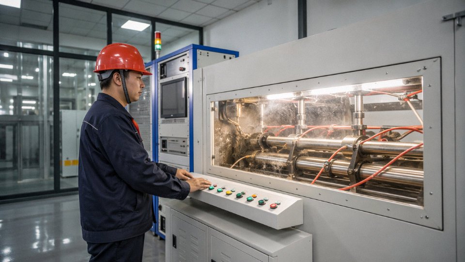
There’s a meaningful gap between a cable factory and a cable trading company with a factory number on its letterhead. The technology indicators worth asking about: Does the plant run continuous vulcanization (CV) lines for rubber-insulated cables? CV processing produces more consistent cross-link density and insulation adhesion than discontinuous methods — you can often see the difference in a polished cross-section cut. Does the facility spark-test 100% of output, not just sample lengths? For 600 V-rated Type 4 cable, 10 kV online spark testing is standard practice. Automated, computer-controlled stranding equipment is worth asking about too, because lay length consistency directly affects cable flexibility and current-carrying balance in multi-conductor designs.
Evaluating a Sample Before Committing to Bulk
Request a 2–3 meter sample before the purchase order goes out. Measure the overall diameter and each conductor cross-section with a calibrated micrometer and compare against the datasheet tolerances — typically ±5–8% on diameter depending on the standard. Weigh a precisely cut 1-meter length and compare it against the theoretical weight per meter in the datasheet; a shortfall of more than roughly 5% usually means undersized conductors or reduced jacket thickness. Cut the cable cleanly, photograph the cross-section, and check conductor concentricity and whether the insulation wall is uniform with no visible voids or bubbles. If you can access a portable spark tester, run the sample at the rated test voltage. These checks take under an hour and will catch most commodity substitution issues.
Jinda’s Manufacturing Footprint and Export Track Record
Shandong Jinda Special Cable Group has been in continuous production since 1987, operating five production bases across China with a combined 470,000 m² of manufacturing space. The flexible cable and rubber cable product lines — which cover Type 4 equivalents and related heavy-duty designs — are served by dedicated production infrastructure including CV vulcanization lines and automated stranding equipment. Over 1,000 employees support operations spanning R&D, production, and technical support.
Export experience covers more than 50 countries, with meaningful volume into mining-intensive markets in Africa, Australia, South America, and Southeast Asia. Those regions have demanding site conditions and, in several cases, strict local approval requirements — which means the documentation and certification processes are already well-practiced rather than assembled on request.
Technical Support and Documentation for International Projects
For international mining and infrastructure projects, Jinda’s pre-order process includes specification review — particularly useful when translating between North American AWG/kcmil sizing conventions and IEC mm² conductor cross-sections, or when a project spec calls for a configuration (say, three power cores plus a ground monitor conductor plus a pilot core) that needs to be built to order rather than pulled from stock.
Documentation packages routinely include factory test reports, material certificates for insulation and jacket compounds, country-of-origin certificates, and packing lists formatted for customs clearance. After-sales technical support covers installation questions, which matters more than it sounds — Type 4 flexible cable has specific minimum bend radius and termination requirements that field crews occasionally get wrong on first deployment.
Lead Times and Logistics Realities
Realistic production lead times for Type 4 and equivalent heavy-duty flexible cable run roughly 4–10 weeks, depending on conductor cross-section, configuration complexity, and order quantity. Larger cross-sections above about 185 mm² and multi-core designs with embedded pilots or ground monitors sit toward the longer end. Sea freight from Chinese ports to major destinations — Rotterdam, Sydney, Durban, Houston — adds typically 3–6 weeks depending on routing and carrier availability.
Export packaging is available on wooden drums or steel reels; steel reels are worth specifying for long-length orders in harsh transit environments, as they handle rough port handling better. For ongoing mining projects or long-term infrastructure maintenance contracts, a blanket purchase order with scheduled release quantities is genuinely worth structuring — it locks in pricing, reserves production capacity, and cuts lead time on subsequent releases because raw material procurement and production scheduling are already in motion.