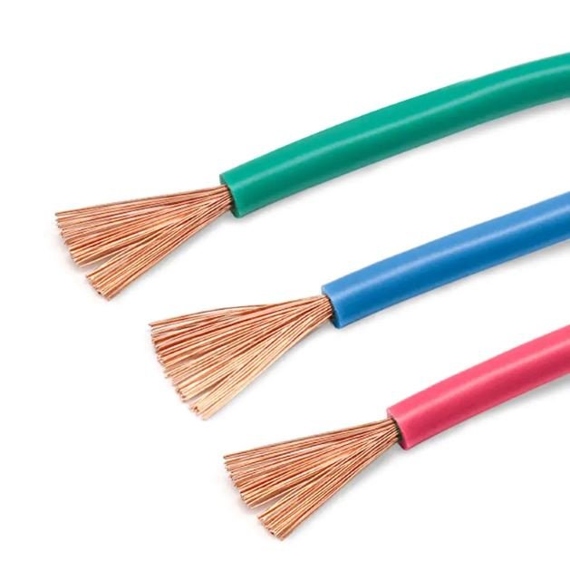
Specifying the wrong cable type — or treating all telecom cable as interchangeable — is one of the more expensive mistakes a procurement team can make quietly. A warehouse that orders Cat5e because it’s cheaper, then discovers the new VoIP and IP-camera system needs 10 Gbps backbone throughput, is looking at a full rip-and-replace inside 18 months. On a mid-size industrial campus that’s easily a six-figure remediation cost, not counting the downtime while contractors work around live production systems.
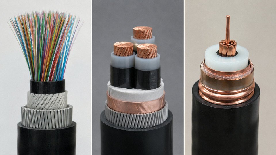
The three types of cables currently used for telecommunications are twisted pair copper cable, fiber optic cable, and coaxial cable. Twisted pair handles most LAN and structured cabling work, with performance ranging from 1 Gbps at Cat5e up to 40 Gbps at Cat8 over short runs. Fiber optic cable carries long-distance and high-bandwidth traffic with attenuation as low as 0.2 dB/km on single-mode. Coaxial cable remains standard for RF, CATV, and certain legacy broadband distributions.
What makes this worth understanding beyond the basics is that the global telecom cable market sits somewhere between USD 22 and 25 billion, growing at roughly 7–9% annually through 2030 — pushed hard by 5G densification and FTTH buildouts. That growth is reshaping which cable types actually get specified, in which applications, and at what volumes. The tradeoffs between copper, glass, and coax are no longer purely technical; they’re procurement decisions with real supply-chain implications.
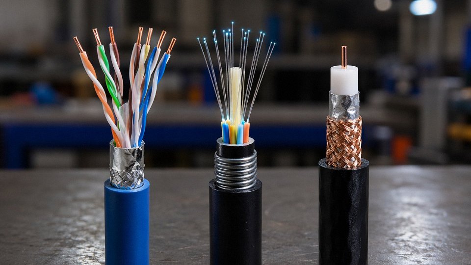
Twisted Pair Cable: Construction Tiers, Shielding Grades, and Bandwidth Ceilings by Category
Why the Twist Itself Does the Heavy Lifting
The fundamental noise-cancellation mechanism in twisted pair cable isn’t the jacket, the shield, or even the conductor quality — it’s the geometry. Each pair is twisted at a specific rate, measured in turns per meter, and the two conductors within that pair carry equal but opposite signals. Any external electromagnetic field induces roughly the same noise voltage on both conductors simultaneously. Because the receiver measures only the difference between the two signals, that common-mode noise cancels out. This is balanced differential signaling, and it works surprisingly well without any metallic shielding at all — provided the twist rate is consistent and the pairs within a cable have different twist rates from each other. That last point matters more than most buyers realize: identical twist rates between pairs cause pair-to-pair crosstalk (NEXT), which is why manufacturers guard their twist-rate specifications closely. Cheaper cables with sloppy twist uniformity fail alien crosstalk tests even when they pass basic attenuation checks.
The Category Ladder — Where Each Tier Actually Stops
Cat5e is the floor for anything built in the last fifteen years. It handles 1 Gbps at 100 m with a 100 MHz bandwidth ceiling, and it’s still sitting in millions of installed horizontal runs. Cat6 holds 1 Gbps as well but at 250 MHz, which gives more headroom against noise and marginally better return loss — the real-world difference in a clean office environment is modest, but in electrically noisy industrial settings the extra margin earns its cost.
Cat6A is where the jump becomes meaningful. At 500 MHz and 10 Gbps over 100 m, it’s the current default for new commercial construction and data center horizontal cabling. The catch is physical size: Cat6A cables are noticeably thicker than Cat6 — typically 7–8 mm vs. 5.5–6 mm — which affects conduit fill calculations. Underestimate that in a 200-drop installation and you’re re-pulling conduit.
Cat7 reaches 600 MHz and 10 Gbps, but its proprietary GG45 or TERA connector ecosystem never achieved broad adoption. Most network planners skip it.
Cat8 is a data center cable, not a building backbone. It supports 25–40 Gbps at up to 2000 MHz but only over 30 m. Specify it for top-of-rack switch interconnects, not horizontal runs.
Shielding Configurations and What They Actually Buy You
UTP — unshielded twisted pair — remains the dominant choice for standard office and light commercial cabling. Well-manufactured UTP with proper installation (no sharp bends, no bundling near power cables) performs reliably up through Cat6A.
Once you’re near variable-frequency drives, high-current bus bars, or any industrial machinery, shielding earns its premium. FTP (foil over all pairs) adds a continuous aluminum-polyester foil that provides roughly 30–40 dB of additional EMI rejection across the common frequency range, depending on shield continuity and grounding quality. S/FTP — individual foil per pair plus an outer braided shield — is the rigorous option, and it’s what Cat7 and Cat8 cables use by definition. The braid handles lower-frequency interference; the per-pair foil handles crosstalk. Both must be properly grounded at one end (or both ends in some configurations) or they can become antennas rather than shields. That’s an installation discipline issue as much as a cable specification issue.
Jacket Materials and Regulatory Mandates
PVC jackets dominate outdoor and general-purpose runs where cost controls. In plenum spaces — the air-handling ceiling voids and raised floors common in commercial buildings — PVC is prohibited under NEC Article 800 because burning PVC releases hydrochloric acid gas. LSZH (low-smoke zero-halogen) compounds are mandated in these environments and in tunnel installations under IEC 60332-3, precisely because toxic smoke kills people before fire does in confined spaces. PE (polyethylene) jackets are the choice for direct-burial and outdoor aerial runs due to UV and moisture resistance, though they’re stiffer and harder to terminate in tight spaces.
Conductor Gauge and Construction: Solid vs. Stranded
Permanent horizontal links — wall to patch panel — use solid 23 AWG copper. Solid conductors have lower insertion loss (roughly 3–5% better than stranded at equivalent gauge) and better return loss characteristics, which matters over a full 100 m channel. Patch cords use stranded 26 AWG or 28 AWG for flex life; a solid conductor bent thousands of times will eventually work-harden and crack. Don’t mix them up in permanent installations — stranded 24 AWG used as a horizontal run will fail channel insertion loss at Cat6A frequencies before the run hits 90 m.
Cat6A solid 23 AWG copper cable meets both TIA-568-C.2 and ISO/IEC 11801 channel performance requirements for 10GBASE-T at 100 mTrue
TIA-568-C.2 and ISO/IEC 11801 both specify Cat6A/Class EA channel requirements that support IEEE 802.3an (10GBASE-T) at 100 m, with solid 23 AWG as the standard conductor size for permanent link compliance.
Jinda’s twisted pair production lines are qualified against ISO/IEC 11801, TIA-568-C.2, and EN 50173, which between them cover the dominant specification frameworks in North America, Europe, and international project tenders. For procurement managers sourcing at volume across multiple regions, that multi-standard alignment avoids the headache of parallel qualification audits.
Coaxial Cable: Impedance Matching, Signal Loss Profiles, and When It Still Outperforms Alternatives
Coaxial cable gets written off as legacy technology constantly, usually by people who’ve never had to feed 50 watts of RF into an antenna at the top of a 40-meter tower or run signal through a kilometre of mining tunnel. The reality is that coax remains the technically correct choice for a specific and durable set of applications — and getting it wrong in those contexts doesn’t just reduce performance, it causes standing wave problems, connector failures, or outright signal collapse.
Construction and Why the Geometry Matters
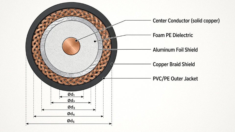
The layered structure of coaxial cable isn’t arbitrary. A center conductor — solid copper, stranded copper, or copper-clad aluminium (CCA) depending on the cost tier — sits surrounded by a dielectric, typically foam polyethylene or solid PE. Foam PE has lower dielectric constant (roughly 1.45–1.50 versus 2.25 for solid), which directly reduces attenuation per unit length. Outside that sits the shielding, almost always a combination of aluminium foil and copper braid, and then an outer PVC or PE jacket.
What this geometry produces is a self-shielding transmission line with tightly controlled characteristic impedance. The electromagnetic field is fully contained between the center conductor and the shield — it doesn’t radiate, and external fields don’t couple in. Twisted pair relies on differential cancellation to achieve noise rejection; coax achieves isolation through geometry. That’s a meaningful difference when you’re working in high-RF environments or near heavy industrial EMI sources.
50-Ohm Versus 75-Ohm: Mismatch Is Not a Minor Problem
The two dominant impedance standards exist for different physical reasons. 75 ohms approximates minimum attenuation in an air-dielectric coaxial line. 50 ohms is a practical compromise between minimum attenuation and maximum power handling. So: CATV, satellite distribution, and broadcast video use 75-ohm cable (RG-6, RG-11, RG-59). RF transmitters, base stations, test benches, and amateur radio installations use 50-ohm cable (RG-58, RG-213, LMR-400).
Connecting a 50-ohm transmitter to a 75-ohm feedline without a matching network causes signal reflection.True
Impedance mismatch creates a discontinuity that reflects a portion of the transmitted signal back toward the source, quantified as return loss. A 50-to-75-ohm mismatch produces roughly 14 dB return loss, meaning measurable reflected power that reduces effective transmission and can stress transmitter finals under high-power conditions.
In practice, technicians sometimes grab whatever coax is on the shelf. On a low-power CCTV run it might not visibly matter. On a cellular macro site feedline carrying tens of watts, the reflected energy is enough to trigger PA protection shutdowns. I’ve seen installations where the fault was traced to a single wrong-impedance jumper after days of troubleshooting.
Attenuation Benchmarks and Trunk Length Decisions
Attenuation figures depend on frequency, and they rise sharply as frequency increases — which is the fundamental reason coax struggles against fiber at high data rates over long distances. Typical values at 400 MHz: RG-6 loses roughly 6 dB per 100 ft, RG-11 around 4 dB per 100 ft, and low-loss cable like LMR-400 approximately 2.7 dB per 100 ft. These aren’t negotiable — they’re set by the cable’s conductor size, dielectric material, and shield construction.
In a DOCSIS 3.1 HFC distribution network, the difference between RG-6 and RG-11 on trunk runs is the difference between needing an amplifier every 150 metres or pushing past 200 metres before signal budget runs out. RG-11’s larger diameter (and higher material cost) is genuinely worth it on trunk segments; using RG-6 throughout to save money during build-out typically means more amplifier nodes, higher opex, and more failure points long-term.
Applications That Twisted Pair and Fiber Can’t Easily Replace
Leaky feeder cable in tunnels and mines is the clearest example. This is a modified coaxial cable with periodic slots in the outer shield, deliberately allowing RF to radiate along the cable’s length to provide continuous radio coverage in underground environments where antennas can’t achieve line-of-sight. Ethernet cable is useless here; fiber carries no RF signal. Coax is the only medium that works.
Antenna feedlines on cellular macro towers are another case. The run from the radio unit to the antenna array might be 20–40 metres of continuous exposure to weather, UV, mechanical vibration, and temperature cycling from −40 °C to +70 °C in harsh climates. Fiber can handle that physically, but the antenna interface is RF — you need a coaxial feedline, full stop. For 5G sub-6 GHz and increasingly for mmWave installations, connector interface selection matters: 4.3-10 connectors have largely displaced DIN 7/16 on new deployments because of their smaller form factor and push-pull locking mechanism, while N-type remains standard on test equipment and some legacy infrastructure. The cable itself needs to be rated for the frequency band — jumper cables for mmWave (24–40 GHz) require phase-stable, very low-loss construction that’s significantly more demanding than standard RG-6 production.
High-power RF testing environments — antenna ranges, EMC chambers, broadcast transmission — also rely on coax specifically rated for power handling, which fiber cannot provide at all.
Standards, Compliance, and Procurement Considerations
Relevant standards across coaxial cable applications include the IEC 61196 series (covering mechanical and electrical performance by cable type), MIL-C-17 for military and aerospace-grade coaxial cables where environmental qualification is mandatory, and the SCTE standards suite governing coaxial cable performance in HFC plant, including SCTE 74 for physical specification and SCTE 87-1 for coaxial cable component interoperability in DOCSIS networks.
Procurement managers sourcing for HFC build-outs or cellular deployments should confirm whether the manufacturer’s production is aligned to these standards, not just declared compliant. Jinda’s production lines cover RG-6, RG-11, and custom-impedance coaxial designs, including PE- and LSZH-jacketed variants for different installation environments. For trunk runs in FTTH-overlay HFC networks or CCTV distribution in large campuses, coaxial cable’s combination of mechanical robustness, predictable attenuation budget, and cost-per-metre relative to fiber makes it the realistic procurement choice — not nostalgia.
Fiber Optic Cable: Single-Mode vs. Multimode Variants, Attenuation Physics, and FTTH/5G Backhaul Deployment Realities
Glass carries light. That’s the elegant premise, and the physics behind it shapes every procurement and design decision you’ll make with fiber optic cable.
How Light Actually Travels — Total Internal Reflection and Core Geometry
Light entering the fiber core bounces off the cladding interface repeatedly, traveling the cable’s length without escaping — a phenomenon called total internal reflection. The ratio of the core’s refractive index to the cladding’s determines the numerical aperture (NA), which controls the acceptance angle of incoming light. A wider NA captures more light but introduces more modal dispersion. This is where core diameter becomes decisive: single-mode fiber runs an 8–10 µm core, narrow enough that only one propagation path (one mode) exists at operating wavelengths of 1310 nm or 1550 nm. Multimode fiber opens that core to 50 µm or 62.5 µm, letting hundreds of modes travel simultaneously — useful at short distances, increasingly problematic as the modes arrive at slightly different times and smear the signal.
OS1 vs. OS2 Single-Mode: The Low-Water-Peak Difference That Matters for Long Runs
Both OS1 and OS2 are single-mode, but OS2’s ultra-low-water-peak (ULWP) profile — attenuation ≤0.2 dB/km at 1550 nm, versus OS1’s ≤0.4 dB/km — is what makes 80 km unamplified spans practical. That gap matters in metro and long-haul backhaul, where every amplifier site you can eliminate saves roughly $15,000–$40,000 in equipment and civil works, depending on location and access difficulty. OS2 cable conforming to ITU-T G.652D is effectively the default for any new outside-plant fiber deployment. If your route runs through tight bend radii — building risers, FTTH drop cables, indoor distribution — G.657A1 or G.657A2 bend-insensitive fiber reduces macro-bend losses at radii down to about 10 mm (A2) without meaningful attenuation penalty on the straight runs.
Multimode Grades: OM1 Through OM5 and Where Each Actually Belongs
OM1 (62.5 µm core) is legacy. You’ll find it in older enterprise buildings, and replacing it is usually worthwhile the moment you need reliable 10G beyond 33 m. OM3 and OM4 both run 50 µm cores, but OM4’s laser-optimized profile delivers an effective modal bandwidth (EMB) of roughly 4700 MHz·km versus OM3’s ~2000 MHz·km — that translates to 100G over 100 m on OM4, versus 100 m at lower channel counts on OM3. OM5 (also 50 µm, specified under TIA-492AAAD) adds wideband multimode capability supporting shortwave division multiplexing (SWDM) across 850–953 nm, extending 100G reach and enabling 400G architectures in hyperscale data centers where re-pulling cable is expensive. In practice, most enterprise data center builds today go straight to OM4 minimum; OM5 is worth the modest premium only if you’re planning a 400G upgrade within the cable’s service life.
OM4 multimode fiber supports 100G Ethernet at distances up to 150 mTrue
Per TIA-492AAAD and IEEE 802.3, OM4 supports 100GBASE-SR4 to 100 m and certain 100G implementations to 150 m using parallel optics, consistent with its EMB specification of approximately 4700 MHz·km.
Outdoor Cable Constructions — Matching the Build Type to the Environment
The fiber’s optical spec is only part of the story. How it’s packaged determines service life in the field.
Loose-tube construction — individual fibers floating in gel-filled tubes inside the outer jacket — handles outdoor temperature swings well because the fiber isn’t mechanically coupled to jacket expansion. Standard for direct-burial and duct installation. Tight-buffer construction bonds the secondary coating directly to the fiber, making cables stiffer and more suitable for indoor risers and short inter-building runs where flexibility and ease of termination matter more than temperature cycling performance.
Ribbon fiber bundles 12 or 24 fibers in a flat, bondable array; mass fusion splicing a 288-fiber ribbon cable takes roughly 20–30 minutes versus several hours of individual splicing. That speed difference is why ribbon cable dominates high-density FTTH feeder routes and central office builds. Armored designs — corrugated steel tape or interlocked armor — are necessary for direct-buried routes with rodent exposure or rocky terrain where mechanical damage is a realistic threat, not just a spec-sheet precaution.
FTTH Economics and Why Fiber Is Winning the National Broadband Argument
Fiber optic cable supports symmetrical service from 1 Gbps up to 10 Gbps, with practical lifespans exceeding 30 years and near-zero degradation from moisture ingress or temperature variation once properly installed. Copper degrades measurably over time — oxidation, moisture, physical stress. Fiber doesn’t, which is why the total cost of ownership calculation tilts toward fiber even when upfront civil works costs run 2–4× higher per-home-passed than copper overlay. Broadband programs across Southeast Asia, the Middle East, and Europe have internalized this; national FTTH targets in countries like Saudi Arabia, Vietnam, and Poland are pulling cable demand hard enough that lead times on OS2 loose-tube cable stretched to 16–20 weeks at peak in 2022–2023.
5G Fronthaul and Midhaul: Why OS2 DWDM Cable Is the Only Viable Path at Scale
eCPRI (Enhanced Common Public Radio Interface) — the functional split between baseband and radio units in distributed 5G RAN architecture — demands roughly 25 Gbps per carrier per sector, with end-to-end latency targets under 100 µs. Multimode fiber simply can’t cover the distances involved between radio units and DU/CU sites, which typically run 300 m to several kilometers. OS2 single-mode cable, combined with DWDM optics that stack multiple 25G or 100G wavelengths on a single fiber pair, is how operators are actually building fronthaul rings. A single 12-fiber OS2 cable can carry 96 DWDM channels per fiber pair, meaning enormous capacity headroom for future radio layer expansion without re-trenching.
Standards Compliance and Specification in Practice
For procurement engineers: OS2 single-mode cable should reference ITU-T G.652D (standard single-mode) or G.657A1/A2 (bend-insensitive) and IEC 60793-2-50. Multimode OM4 references TIA-492AAAD; OM5 references TIA-492AAAE. These aren’t interchangeable documents — G.652D and G.657 cover different bending performance regimes, and mixing them in a single outside-plant route without checking connector-end compatibility has caused real-world reflection problems at splice points. Jinda’s fiber optic cable products are manufactured and tested to these ITU-T, IEC, and TIA standards, with full documentation available for project-specific qualification requirements. For bulk infrastructure procurement — FTTH feeder, 5G fronthaul, campus backbone — having a supplier whose production traceability aligns with these standards from the first production reel, not just on a type-approval sample, is what determines whether your commissioning tests pass on the first sweep.
Direct Performance Comparison: Bandwidth, Distance, EMI Immunity, Cost-per-Meter, and Lifespan Across All Three Types
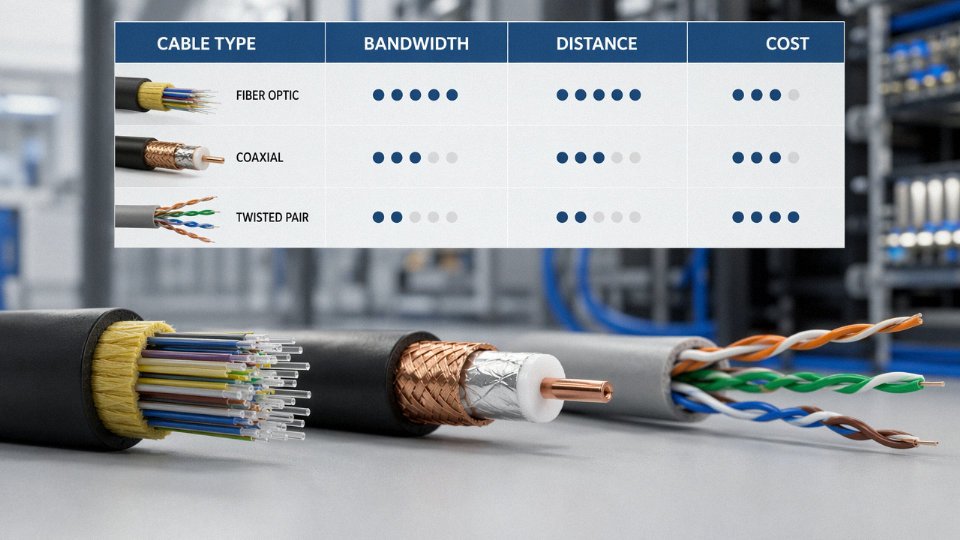
Choosing between twisted pair, coaxial, and fiber isn’t purely a bandwidth decision. In practice, the cable type that wins on paper loses on the job site when you factor in conduit fill ratios, existing infrastructure, local labor rates for fusion splicing, or the EMI environment in the building. The table below gives you a working reference — treat the ranges as real-world installed figures, not lab specs.
Comparative Performance Table
| KPI | Twisted Pair (Cat6A) | Coaxial (RG-6/RG-11) | Single-Mode Fiber (OS2) |
|---|---|---|---|
| Maximum bandwidth | 10 Gbps at 100 m | 3 Gbps (DOCSIS 3.1 HFC) | 100 Gbps+ (DWDM capable) |
| Max practical distance, no repeater | 90–100 m | 300–600 m (signal-dependent) | 40–80 km (loss-budget dependent) |
| EMI immunity | Low–moderate (STP improves) | Moderate (shielded by design) | Complete — zero susceptibility |
| Typical installed cost/meter (USD) | $1.50–$4.00 | $2.00–$6.00 | $8.00–$18.00 (labor-intensive) |
| Weight (kg/m) | 0.04–0.07 | 0.10–0.20 | 0.02–0.06 |
| Minimum bend radius | 4× cable OD | 10× cable OD | 15–30× cable OD (connector-end critical) |
| Operating temperature range | –20 °C to +60 °C | –40 °C to +75 °C | –60 °C to +85 °C (varies by jacket) |
| Expected service life | 15–20 years (category-limited) | 20–25 years (amplifier-dependent) | 30–40 years |
Costs above assume North American or Western European contractor labor. In Southeast Asia or Eastern Europe, fiber installed cost can drop to $4–9/m depending on local splicing availability. The coaxial figure reflects HFC trunk cable — drop cable is cheaper.
Total Cost of Ownership Over 20 Years
Fiber’s installed cost per meter can look alarming on a capital budget. Over a 20-year horizon it rarely is. A building structured with Cat6A today will almost certainly need a Cat8 or active-optical rip-and-replace cycle somewhere around year 10–14 as 40 Gbps edge switching becomes standard. That recabling costs money, disrupts operations, and usually runs through conduits that are already full. Single-mode fiber installed today with OS2 glass carries whatever bandwidth protocol the transceivers support — the glass doesn’t care whether you’re running 10GBase-LR now or 400G-ZR in 2035. You’re paying for transceivers, not new cable.
Coaxial HFC plants are a different story. The cable itself lasts, but the cascade of line amplifiers every 300–500 m requires periodic maintenance — typically gain adjustments after temperature swings, capacitor replacements every 7–12 years depending on climate, and occasional housing corrosion in coastal or humid environments. Operators who’ve run HFC for 20+ years will tell you the amplifier labor is the slow budget drain you don’t see on day one.
EMI Sensitivity in Practice
Fiber is genuinely immune — no ground loops, no radiated emissions, no susceptibility to variable-frequency drives, welding equipment, or high-voltage bus bars running nearby. That’s not marketing language; it’s physics. This is why fiber is effectively mandatory in power generation substations, petrochemical control rooms, and secure government communications rooms where even a momentary data corruption event carries serious consequences.
Twisted pair with proper S/FTP screening performs adequately in light industrial environments, but “adequately” is doing real work in that sentence. A Cat6A S/FTP cable running near a poorly bonded motor starter cabinet can still inject noise if the drain wire termination at the patch panel is careless — and in my experience, termination quality on the plant floor is highly variable.
Coaxial sits in between. The outer conductor provides substantial shielding, which is why it handles RF environments well, but it isn’t the right answer near high-current switching gear.
Weight, Bend Radius, and Aerial/Offshore Constraints
For aerial spans, bridge cable trays, and offshore platform raceways, weight matters considerably. A fiber optic cable carrying equivalent bandwidth capacity to a copper bundle weighs roughly 60–80% less. On a 200-meter aerial span between buildings, that difference drives the entire structural load calculation for the support hardware. One strand of single-mode fiber in a tight-buffered cable weighing 20 g/m replaces a Cat6A bundle that might run 60–90 g/m for the same aggregate throughput.
Bend radius is where fiber demands respect. OS2 fiber at a connector end needs careful management — a sharp pull-through a conduit bend is one of the most common causes of latent insertion loss in new installations. Coaxial is actually the least forgiving on sustained bend stress in some configurations; RG-11 kinks irreversibly.
Hybrid Cables and Composite Designs
A growing proportion of real-world deployments don’t pick one cable type — they combine them. Fiber-plus-copper composite cables, sometimes called hybrid or breakout designs, run optical fibers alongside copper power pairs inside a single jacket. This is particularly useful for distributed antenna system (DAS) remote units that need both data transport and local power, and for FTTX drop cable runs where a single drop needs to feed both optical network terminals and legacy copper services in the same premises.
Fiber optic cable is completely immune to electromagnetic interference and cannot radiate or receive RF signals.True
Optical fiber transmits light signals through glass or plastic; it contains no conductive elements in the signal path and therefore cannot act as an antenna, develop ground loops, or be affected by external electromagnetic fields.
Jinda’s composite cable range addresses exactly these mixed-media deployment needs — integrating optical elements with copper pairs in configurations suited for DAS infrastructure, remote radio unit feeds, and FTTX last-drop applications where running separate cable types is impractical or cost-prohibitive.
Standards, Certifications, and Regulatory Compliance Requirements for Telecom Cable Procurement
Specifying the right cable type is only half the job. Getting it through customs, past a building inspector, and accepted on a project specification requires a parallel paper trail — and in my experience, this is exactly where procurement timelines slip. A shipment of otherwise perfectly good fiber can sit in a bonded warehouse for weeks because the importer couldn’t produce a CPR Declaration of Performance. Getting ahead of compliance requirements before issuing a purchase order is not bureaucratic caution; it’s schedule protection.
International Standards Bodies and Which Cable Types They Govern
The governing landscape is fragmented by design, because telecom cable spans electrical engineering, optical physics, and construction safety — three communities that don’t share a standards table.
IEC TC46 owns the coaxial and RF cable space: connector interface dimensions, impedance tolerances, and the mechanical test methods that matter for outdoor antenna feedlines and CATV trunk cable. Fiber optic cable sits under IEC TC86, which publishes the IEC 60793 series (optical fiber specifications) and IEC 60794 (optical cable construction and test methods) — these are the documents your fiber supplier’s datasheet should be tracing back to. For structured cabling as a system, the relevant body is ISO/IEC JTC1 SC25, whose ISO/IEC 11801 series defines channel performance requirements for everything from Cat5e horizontal runs to OM4 backbone links. ITU-T Study Group 15 handles optical transport at the network layer, which matters more to carriers and backhaul planners than to building-level procurement, but becomes relevant when specifying OS2 cable for long-haul or metro DWDM deployments. In North America, TIA TR-42 produces the ANSI/TIA-568 series — the dominant structured cabling standard on that continent — and its category definitions for twisted pair, while broadly aligned with ISO/IEC 11801, are not identical. Don’t assume a cable marked “Cat6A compliant” satisfies both without checking the test report headers.
CPR Classification in the European Union
The EU’s Construction Products Regulation (CPR) classifies cables by reaction-to-fire performance, running from Aca (best, essentially non-combustible) down through B1ca, B2ca, Cca, Dca, Eca, to Fca. For most commercial buildings and all public infrastructure projects in Europe, the minimum acceptable class is now Cca-s1,d1,a1 — meaning limited flame spread, minimal smoke, no flaming droplets, and low acid gas emission. Specifying anything below Cca on a hospital, school, or transit project in Germany, France, or the Netherlands will get your submittal rejected. The “s1,d1,a1” suffix matters as much as the letter class; a cable can pass Cca for flame spread but still fail smoke or droplet criteria.
Fire Performance Test Standards and LSZH Engineering
Four IEC test standards together define a cable’s fire safety profile. IEC 60332-1 tests a single cable’s resistance to vertical flame propagation — essentially a minimum entry requirement. IEC 60332-3 tests a bundled installation, which is far more demanding because real installations are never single cables. IEC 60754 measures halogen acid gas emission from the jacket and insulation materials during combustion; anything using PVC will struggle here. IEC 61034 quantifies smoke density. LSZH (low-smoke zero-halogen) jacket compounds are specifically formulated to pass all four simultaneously, which is why they’ve largely displaced PVC in European commercial and infrastructure projects — even though LSZH jackets are typically 15–30% more expensive per meter and require more careful handling at low temperatures due to reduced flexibility.
RoHS and REACH: Material Declaration Requirements
RoHS compliance restricts ten hazardous substances — lead, mercury, cadmium, hexavalent chromium, certain phthalates among them — and is a legal requirement for placing electrical and electronic equipment on the EU market. REACH goes further, requiring suppliers to disclose substances of very high concern (SVHC) present above 0.1% by weight in any article. Public infrastructure tenders in the EU, and increasingly in South Korea, Japan, and parts of the Gulf Cooperation Council, now require full material declarations as a bid submission document, not just a checkbox. If your cable supplier can’t produce a substance declaration with CAS numbers and weight fractions, that is a sourcing risk worth taking seriously before the tender deadline.
REACH requires cable suppliers to proactively disclose SVHCs above 0.1% by weight in their products when requested by customers or regulatory authorities.True
Under Article 33 of REACH Regulation (EC) No 1907/2006, suppliers of articles containing SVHCs above 0.1% w/w must provide sufficient information to allow safe use, including the substance name, upon customer request or when the article is destined for a consumer.
UL Listing for North American Markets
Three UL standards govern communications cables in the US and Canada. UL 444 covers general communications cable construction and is the baseline. UL 1666 is the riser rating (CMR), requiring cables to resist flame spread vertically through a two-story shaft — relevant for any inter-floor backbone run. UL 910, the plenum rating (CMP), is the most demanding: cables must pass the Steiner Tunnel test, which exposes a 25-foot cable sample to a specific flame and airflow, measuring peak optical density of smoke and flame spread distance. CMP-rated cable typically uses FEP or similar fluoropolymer insulation, which is why it costs noticeably more than riser cable. Installing non-CMP cable in an air-handling plenum space is a code violation in the US that will trigger a failed inspection and, in a fire event, liability exposure that no project margin justifies.
Quality Infrastructure at Jinda
Jinda operates under ISO 9001:2015 certification across its five production bases in China. In-house laboratories are equipped for the full suite of copper cable electrical tests — return loss, insertion loss, near-end crosstalk (NEXT), power sum attenuation-to-crosstalk ratio far-end (PSACR-F) — as well as optical OTDR testing for fiber product verification. Export shipments are accompanied by third-party type-approval certificates, which directly address the customs documentation requirements and project specification submittals that procurement teams encounter on international contracts. For buyers sourcing cable across multiple regulatory jurisdictions simultaneously, having a supplier whose documentation package is already built around IEC, CPR, RoHS/REACH, and UL requirements reduces the administrative load considerably.
Installation Environment Decision Guide: Matching Cable Type to Underground, Aerial, Indoor, Industrial, and Marine Conditions
Specs on a datasheet tell you what a cable can do. The installation environment tells you what it must survive. Getting that match wrong doesn’t just cause early failure — it causes the kind of failure that happens eighteen months after commissioning, in a conduit you can’t access without a road closure.
Underground Direct Burial
Soil conditions vary enormously, and the cable construction needs to follow. Gel-filled loose-tube fiber with a PE outer jacket is the workhorse for most direct-burial fiber runs — the gel blocks longitudinal water migration, and PE resists most soil chemicals adequately in neutral-to-mildly-acidic conditions. Where groundwater is persistent or the soil is alkaline clay (common in coastal lowlands and irrigated agricultural zones), you want a double-jacketed construction or an HDPE inner duct pulled through a separate conduit system. The conduit approach costs more upfront — roughly 15–30% more per meter of trench, depending on conduit grade and local labor — but it gives you future replaceability without re-digging.
Frost heave is underappreciated. In climates where the frost line exceeds 800 mm, armored fiber (corrugated steel tape or wire armor over the gel-filled core) handles the shear stress far better than unarmored cable. Rodent zones — particularly in agricultural or forested areas where burrowing rodents are active — demand either wire-armored construction or conduit. No exceptions. A gnawed fiber cable at 1.2 m depth is a miserable fault to locate.
Direct-buried armored coaxial still makes sense for CCTV perimeter installations and some RF distribution runs where the distances are short, the bandwidth ceiling isn’t a constraint, and the installation team already has coax termination skills on-site.
Aerial Lashing on Utility Poles
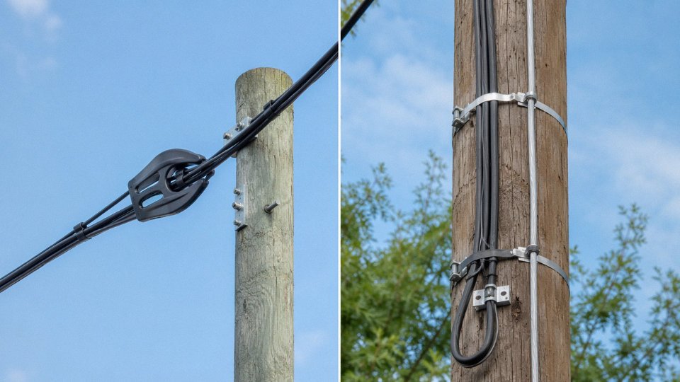
Wind and ice loading govern aerial cable sizing more than bandwidth does. Self-supporting figure-8 cable — with a steel messenger wire integrated into the jacket — eliminates the separate lashing step and keeps sag predictable over span lengths of 50–80 m in most utility pole configurations. For longer spans or high ice-load zones (northern latitudes, mountain passes), you need to verify the messenger wire’s tensile rating against your calculated design load, not just the catalog default. UV stabilization in the outer jacket is non-negotiable; an unstabilized HDPE jacket in full sun exposure degrades noticeably within 3–5 years.
Figure-8 aerial twisted pair — essentially a Cat5e or Cat6 cable with an integrated messenger — remains a practical last-mile copper extension in markets where fiber FTTH rollout is still years away. It’s not glamorous, but it works for voice and sub-100 Mbps broadband delivery to rural distribution points.
Indoor Plenum and Riser Routing
Building codes in North America mandate CMP-rated (plenum) cable in any air-handling space — return air plenums, raised-floor data rooms used for airflow. In European jurisdictions, the equivalent is Cca or B2ca under EN 50575. The practical difference matters: standard PVC-jacketed cable produces dense, toxic smoke when it burns. LSZH (low smoke zero halogen) compounds used in plenum and riser cables are formulated with flame-retardant additives — typically aluminum trihydrate or magnesium hydroxide systems — that suppress both flame spread and smoke density. The jacket is stiffer and slightly more brittle in cold temperatures, which affects pull-through in tight conduit bends. Installers sometimes underestimate this and crack jackets on tight 90-degree pulls in cold weather.
Never use outdoor-rated fiber distribution cable in a plenum space. The PE or HDPE jacket compounds used for UV and moisture resistance are exactly the wrong chemistry for fire performance indoors.
Industrial Environments
Factories, substations, and offshore platforms share three threats: electrical noise, mechanical impact, and chemical exposure. Armored fiber optic cable — stainless steel interlocked armor for maximum crush resistance, or corrugated steel tape for a lighter-weight alternative — handles the mechanical side. For data transmission, fiber’s inherent EMI immunity is the real advantage here; running copper near large VFDs or transformer banks produces noise floors that even well-screened SFTP cable struggles with above certain cable lengths.
Where copper is necessary (short runs to sensors, field instruments, or patch panels close to the noise source), SFTP with an LSZH jacket is the correct spec. The foil-plus-braid screening combination gives 40–60 dB screening attenuation across the frequency range that most industrial interference occupies. Hydrocarbon exposure — oil mist, solvent splash — requires jacket compound verification; standard PVC swells and softens in prolonged contact with many hydrocarbons, while specialized compounds (PVDF, TPE-based formulations) hold up far better.
Stainless steel interlocked armor on fiber optic cable provides superior crush resistance compared to standard corrugated steel tape armor in high-impact industrial environments.True
Interlocked armor design distributes radial crushing loads across the interlocked segments, whereas corrugated steel tape relies on hoop strength alone; interlocked construction is generally specified for environments with direct mechanical impact or heavy equipment traffic.
Data Center Horizontal and Vertical Cabling
The migration path inside a data center follows rack density and switch-to-switch distances. Cat6A copper handles horizontal runs to 100 m and remains cost-effective for server access at current 10GBASE-T speeds. Once inter-switch distances push beyond 30 m or bandwidth requirements hit 40–100 Gbps, OM4 or OM5 multimode fiber is the next step — lower cost than OS2 single-mode at data center scale, simpler connectorization, and sufficient for the 100–300 m distances typical of campus-level DCI links. OS2 single-mode becomes necessary for longer inter-building runs or when coherent 400G+ transceivers enter the picture.
Pre-terminated trunk cable assemblies — factory-terminated MPO/MTP trunks pulled from one patch panel to another — routinely cut field deployment time by 40–60% compared to field-terminated individual fibers. The trade-off is reduced flexibility if rack layouts change, so pre-terminated trunks make most sense in stable, high-density spine-leaf architectures rather than edge rows that get reconfigured frequently.
Marine and Offshore Applications
Submarine and marine cables face hydrostatic pressure, continuous water immersion, and biological attack. Anti-teredo worm protection — typically a copper tape or specialized compound layer beneath the outer armor — is essential for shallow-water cable runs in tropical and subtropical waters where teredo activity is significant. Double armor (an inner layer of steel wire armor plus an outer layer) handles both tensile load during laying and protection against trawl gear or anchor drag in cable landing zones.
The secondary coating on the optical fiber itself must be hydrolysis-resistant for long-term immersion; standard UV-cured acrylate coatings degrade over years of seawater exposure without the correct formulation. IEC 60092 governs electrical installations in ships and sets the construction and test requirements for shipboard cable including flame retardancy, halogen content, and mechanical robustness. Jinda’s armored marine cable range is developed to meet IEC 60092 requirements, supporting offshore platform cabling, vessel internal wiring, and nearshore submarine distribution applications.
Frequently Asked Questions About Telecommunications Cable Types
Can fiber optic cable fully replace twisted pair copper in all telecom applications?
No — and this is probably the most persistent misconception among clients who’ve read one too many “fiber is the future” articles. Fiber carries light, not electricity. Power over Ethernet for IP cameras, VoIP desk phones, Wi-Fi access points, and door access controllers requires copper conductors, full stop. The dominant enterprise architecture in practice today — and realistically through at least 2030 — is an OS2 single-mode backbone between floors or buildings, with Cat6A horizontal runs delivering both data and power to endpoints. Ripping out horizontal copper to replace it with fiber saves nothing if you then have to install a separate power distribution system. Hybrid design isn’t a compromise; it’s the correct engineering answer.
What is the difference between STP and FTP shielded twisted pair, and does shielding always help?
FTP (foil twisted pair) wraps a single aluminum foil shield around all four pairs as a group. STP (shielded twisted pair) individually screens each pair with its own foil or braid, then sometimes adds an overall shield on top. The per-pair shielding in STP provides significantly better crosstalk isolation — it matters in Cat7 and Cat8 installations where alien crosstalk is the limiting factor.
Here’s the part that catches plants out: shielding only improves performance when terminated correctly to a bonded, grounded shield bar at both ends. An improperly grounded shield — floated at one end, or connected through a long pigtail to a distant ground point — acts as an antenna. It picks up interference rather than rejecting it. In noisy industrial environments with VFDs and motor starters nearby, I’ve seen ungrounded FTP cable measure worse than a comparable UTP run. The cable isn’t the problem; the installation practice is.
How do I choose between OS2 single-mode and OM4 multimode fiber for a new building?
For runs under roughly 300 meters between switches using 10G or 40G transceivers, OM4 multimode is typically 30–40% cheaper on an installed basis — the transceivers cost considerably less than their single-mode counterparts, and that’s usually where the real delta sits, not in the fiber itself. For campus links over 500 meters, or any run where 100G+ upgrades are on the five-year roadmap, OS2 is the lifecycle-cost-optimized choice. Single-mode has essentially unlimited distance scalability; you replace transceivers, not cable.
OM4 multimode fiber installed cost is typically 30–40% lower than OS2 single-mode for short intra-building runs under 300 m, primarily due to transceiver cost differences.True
The cost advantage of multimode in short-reach applications is well established in structured cabling practice and reflects the significant price gap between VCSEL-based multimode transceivers and coherent or single-mode transceivers at equivalent data rates.
Is coaxial cable still relevant for new infrastructure builds?
Yes, in three specific contexts that aren’t going away: CATV hybrid fiber-coax distribution plant where the final drop to premises remains RG-6 or RG-11 coax; cellular base station antenna feeder cables, including 5G macro site and small cell RF jumpers where low-loss heliax or foam-dielectric coax carries signal between radio units and antennas; and leaky feeder systems in transportation tunnels and underground mining operations where the cable itself functions as a distributed antenna. Outside these niches, specifying new coax for data networking is harder to justify.
What certifications should I require when purchasing telecom cables?
At minimum: ISO 9001:2015 quality management certification from the manufacturer, IEC or TIA type-test reports covering the relevant electrical or optical performance parameters, CPR Declaration of Performance for any EU project (critical for fire-rated cable categories), and UL listing for North American installations. RoHS and REACH material declarations matter increasingly for government and commercial projects. For fiber, request OTDR trace reports. For structured copper, ask for channel and permanent link test reports to TIA-1152 or ISO/IEC 14763-3. A manufacturer who hesitates on any of these documents is a procurement risk.
How does Jinda ensure consistent quality across high-volume international orders?
Jinda’s five production bases across China operate under a unified ISO 9001 quality system with centralized raw material sourcing — copper rod, optical preform, and compound are qualified at group level rather than site by site. In-line production monitoring uses laser diameter gauges and spark testers on every extrusion and jacketing line. Final batch testing runs in accredited laboratories before release. Each export shipment carries factory test certificates, and for certified products, third-party conformity documentation accompanies the goods. For large project orders, pre-shipment inspection by the buyer’s nominated third party is routinely accommodated.
What is the minimum bend radius for fiber optic cable, and why does it matter?
Standard single-mode cable minimum bend radius is typically 20× the cable outer diameter during installation, relaxing to 10× in the final fixed position. Tighter bends cause microbending losses — the waveguide geometry distorts, modes leak into the cladding, and attenuation increases. In bad cases it’s catastrophic: a 3 dB loss from a single tight bend at a cable tray corner will fail a link budget that had no margin to spare.
Bend-insensitive ITU-T G.657A2 fiber tolerates a 7.5 mm bend radius, which is why it’s the standard choice for FTTH drop cable routed through conduit, stapled along baseboards, or pulled through tight riser paths in residential buildings. If you’re specifying indoor drop or distribution cable for FTTH deployment and the BOM doesn’t explicitly call out G.657A2, push back.
How to Specify and Procure the Right Telecom Cable for Large-Scale International Projects: A Practical Buyer’s Checklist
Getting the technical selection right is only half the job. The other half — the one that actually determines whether a project ships on time, passes inspection, and doesn’t generate warranty claims eighteen months later — is procurement execution. What follows is a working checklist built from the kind of specification disputes and late-delivery post-mortems that procurement teams would rather not repeat.
Step 1 — Lock Down the Performance Envelope Before Touching a Catalogue
Write down four numbers before contacting any supplier: required throughput in Gbps, maximum segment length, number of intermediate connections, and your latency budget. These four alone will collapse most of the decision tree. A 10 Gbps campus backbone at 80 m with a clear upgrade path to 25 Gbps in five years points firmly at Cat6A or OM3/OM4 fiber — not Cat5e, not RG-coax. Document the upgrade path explicitly. Specifying to today’s requirement and ignoring the next refresh cycle is how projects end up re-cabling a building six years ahead of schedule.
Step 2 — Map Every Metre of Route to Its Environmental Threat
Indoor riser, outdoor direct-burial, coastal aerial, petrochemical plant floor — each segment carries a different threat profile. Temperature range, UV exposure duration, standing water risk, and the site’s EMI classification (light commercial, industrial, heavy industrial with variable-speed drives or welding equipment nearby) each map to a specific combination of jacket material, armor type, and shielding grade. A LSZH jacket needed for a European transit tunnel is a different compound entirely from the HDPE jacket required for an outdoor FTTH drop in a high-UV climate. Mixing them up on a single bill of materials is a surprisingly common sourcing error.
Step 3 — Build the Standards Matrix for the Destination Country
This step gets skipped most often and causes the most pain at customs or commissioning. EU projects require CPR reaction-to-fire classification and EN 50173 channel performance. North American projects reference TIA-568-C.2 or C.3 and NEC Article 800 for indoor ratings. Middle East tenders increasingly call out SASO and GSO references. Southeast Asian markets — Indonesia, Vietnam, Malaysia — each carry their own national adoption of IEC with local addenda (SNI, TCVN, SIRIM respectively). Confirm, in writing, that the supplier holds current certificates valid in the project jurisdiction. A CE mark does not satisfy a Saudi Aramco specification. Ask for the actual certificate document, not a reference to it.
Step 4 — Demand the Material Data Sheet, Not Just the Product Sheet
Minimum data points worth insisting on: conductor purity (≥99.9% electrolytic copper for twisted pair), dielectric cell structure and material for coaxial cables, fiber core geometry including mode field diameter, 125 µm cladding diameter tolerance, and cutoff wavelength for single-mode, and jacket compound identity including PVC plasticiser type, LSZH oxygen index (typically ≥30% for compliant cable), or HDPE carbon black content for outdoor grades (usually 2–2.5% by weight for adequate UV stabilisation). A supplier who hesitates on any of these is a supplier worth reconsidering.
Copper purity below 99.9% in telecom cable conductors measurably increases DC resistance and degrades high-frequency channel performance, particularly at Cat6A and above.True
IEC 60228 Class B conductors and TIA-568 both specify conductor resistance limits that correlate directly to copper purity and cross-section; impure or aluminium-clad copper conductors fail channel compliance at elevated frequencies.
Step 5 — Verify Production Capacity and Lead Time Architecture
For any order above roughly 50,000 metres, ask for the supplier’s monthly production capacity per cable type — not the theoretical line speed, the actual committed throughput given current order book. Ask whether the manufacturer can split production across multiple bases to compress lead time. Jinda’s five-production-base structure across China exists precisely for this: when a single facility is running at capacity, split scheduling across bases keeps delivery dates realistic rather than optimistic. Confirm the logistics lead time to your port of destination, and build in buffer for seasonal port congestion — Chinese New Year and the Q4 peak both create predictable delays that catch buyers every year.
Step 6 — Write Quality Assurance Provisions Into the Purchase Order, Not an Email
Specify drum length tolerance (±0.5% is standard and enforceable), mandatory OTDR trace or full electrical channel test report for each drum, and a third-party inspection clause at the factory gate for orders above a defined value. Equally important: define the replacement protocol for non-conforming lengths discovered after delivery. Vague warranty language that says “we will discuss” is not a warranty.
Step 7 — Sustainable Procurement Is Now a Tender Requirement, Not a Nice-To-Have
In European, Australian, and Canadian public-sector tenders, EPDs (Environmental Product Declarations), recycled copper content disclosure, and packaging waste reduction commitments are increasingly scored criteria, not optional extras. Request these documents at the RFQ stage. A supplier who cannot provide them is likely to create problems at the tender evaluation stage, regardless of unit price.