Specifying the wrong cable type for a flexible power application doesn’t just mean a wiring job that looks a bit rough — it means premature insulation cracking, nuisance tripping, and in worst cases a fire risk that shuts down an entire line. Procurement teams who treat “flexible cable” as a generic category routinely end up with a fixed-installation product stuffed into a moving application, and the mechanical fatigue shows up within months, not years. Replacement labour, unplanned downtime, and the regulatory headache of a non-compliant installation are all avoidable costs that trace directly back to one under-examined decision early in the cable selection process.
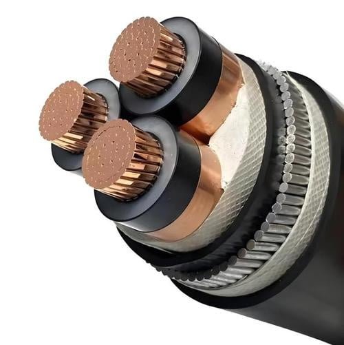
Type 4 power cable is a rubber-insulated, flexible, stranded-conductor cable rated for voltages up to 0.6/1 kV and designed for demanding portable or semi-fixed applications. It uses Class 5 or Class 6 fine-stranded copper conductors per IEC 60228, tolerates operating temperatures from roughly –25°C to +60°C in standard grades, and is built to withstand repeated flexing, mechanical abuse, and exposure to oils and moisture on active plant floors.
What makes Type 4 worth understanding in detail is not the headline rating — it’s the specific combination of conductor construction, compound chemistry, and stranding geometry that separates it from cables that look identical on a spec sheet but fail completely differently in the field. The rest of this article works through exactly that.
Anatomy of a Type 4 Cable: Layer-by-Layer Construction Details
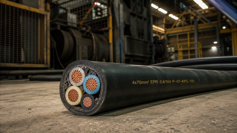
Knowing what a cable is rated for matters less than understanding why it can survive what you’re asking of it. A Type 4 cable’s flex performance, moisture resistance, and service life all trace back to decisions made at each physical layer. Here’s what you’re actually buying.
Conductor Layer
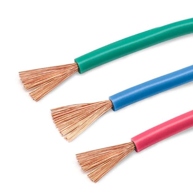
The conductor in a Type 4 cable is fine-wire stranded copper, conforming to IEC 60228 Class 5 or Class 6. The distinction matters in practice: a 25 mm² Class 5 conductor uses roughly 196 individual wires, while a Class 6 equivalent pushes that count higher still, reducing each wire’s diameter and increasing the assembly’s ability to bend without individual strands yielding. That wire count is not a selling point — it is a mechanical necessity for cables designed to flex tens of thousands of cycles in drag chains, cable reels, or trailing applications.
Tinned copper is almost always specified in rubber-insulated designs, and for good reason. Sulfur-bearing vulcanizing agents used in EPR and neoprene compounds will migrate to bare copper surfaces over time, forming copper sulfide at the interface. The result is increased contact resistance at terminations and accelerated insulation degradation. Tinning adds cost — roughly 5–12% on the conductor, depending on copper market conditions and tin plating thickness — but skipping it on a rubber cable is a false economy.
Conductor Insulation Layer
Ethylene propylene rubber (EPR) is the dominant insulation compound in properly constructed Type 4 cables, rated for 90°C continuous operation and handling short-circuit temperatures up to 250°C in some formulations. At –25°C, EPR remains genuinely flexible; PVC at that temperature becomes brittle enough to crack during cable movement, which is exactly why you cannot substitute a PVC-insulated flexible cable in an outdoor winter mining environment and expect the same service life.
EPR also resists ozone and UV degradation better than most thermoplastics, and its moisture absorption is low enough for intermittent wet contact — though it is not a substitute for a submersible cable rating if the application involves permanent immersion.
Typical insulation wall thicknesses, which are set by IEC 60502-1 and related standards, scale with conductor size:
| Conductor Cross-Section | Nominal Insulation Thickness |
|---|---|
| 1.5 mm² | ~0.6 mm |
| 6 mm² | ~0.9 mm |
| 25 mm² | ~1.2 mm |
| 50 mm² | ~1.4 mm |
| 95 mm² | ~1.8 mm |
Actual values vary by standard revision and manufacturer tolerance. Always check the published standard your project calls for rather than relying on a catalogue number alone.
Cording and Assembly Layer
Insulated cores are laid up in a helical assembly with fillers — typically non-hygroscopic rubber or textile cords — packed into the interstitial gaps. This is less glamorous than it sounds but genuinely important: a round, firm cross-section distributes sheath compression evenly during flexing. An oval or loose assembly concentrates stress on the outer cores, shortening insulation life measurably in high-cycle applications. Mining-variant Type 4 cables frequently include a pilot core or earth-continuity check conductor laid into the assembly, which allows ground fault monitoring without interrupting the main circuit.
Inner Sheath (Bedding) Layer
A rubber or TPE bedding extruded over the laid-up assembly serves three functions: it locks core positions against migration during repeated bending, provides a clean cylindrical surface for the outer sheath to bond to, and adds a secondary moisture barrier. Thin or inconsistent bedding is one of the first things worth checking on a supplier sample — press the outer sheath off a cut end and look at surface uniformity.
Outer Sheath Layer
This is where the cable’s environmental resistance lives. Heavy-duty polychloroprene (neoprene), HOFR rubber, or chlorosulfonated polyethylene (CSP, sometimes sold under the trade designation Hypalon) are the standard compound choices. Sheath thickness for most industrial sizes runs 2.0–4.0 mm, with heavier walls applied to larger conductors and more abrasive service environments. Selection logic is straightforward:
- Polychloroprene: general industrial, construction sites, good oil resistance, cost-effective
- HOFR: offshore platforms, shipyards, anywhere requiring simultaneous heat, oil, and flame resistance
- CSP: high-UV environments, chemical splash exposure, situations where long-term ozone resistance is critical
Type 4 cables specified with HOFR outer sheaths provide flame retardancy and oil resistance that standard neoprene sheaths do not reliably deliver in combined hydrocarbon and ignition-risk environments.True
HOFR compound formulations are specifically engineered to meet both IEC 60332 flame propagation and oil-resistance requirements simultaneously; standard polychloroprene passes oil resistance but may not meet the same flame test thresholds depending on compound grade and thickness.
Optional Armoring and Textile Reinforcement
Not every Type 4 cable needs armoring, but trailing-cable and drag-chain applications sometimes justify it. Braided galvanized steel or textile reinforcement can be applied over the bedding layer to resist tensile loads and mechanical abrasion during cable travel. The caveat is real: armoring adds stiffness, and specifying steel wire armor on a cable that needs a 4–6× OD bend radius can effectively negate the flexibility advantage the fine-wire conductor was chosen to provide. For drag-chain use specifically, most experienced cable engineers prefer textile braid or no armoring at all, relying instead on the sheath compound’s abrasion resistance and a conservatively derated flex cycle rating.
Key Standards That Govern Type 4 Cable: IEC, AS/NZS, BS, and Mining Codes
Standards multiply fast once you cross borders, and a cable that meets spec in Sydney can fail a compliance audit in Hamburg or Johannesburg if the specifying engineer didn’t check which document was actually referenced. Here’s how the main frameworks relate to each other — and where they diverge.
IEC 60245-4: The Global Baseline
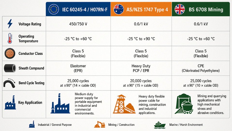
IEC 60245 is the international umbrella standard for rubber-insulated cables, and Part 4 specifically covers heavy rubber-sheathed flexible cables — the designation most engineers will recognise is H07RN-F. Voltage class is 450/750 V, conductor temperature rating typically 60°C for standard grades (rising to 90°C or beyond for heat-resistant formulations). The construction requirements in IEC 60245-4 — multi-wire stranded copper, polychloroprene or equivalent outer sheath, minimum sheath thickness scaled to cable diameter — closely define what the global market loosely calls “Type 4 performance.” Not every supplier will use that phrase, but if a data sheet references H07RN-F and IEC 60245-4, you’re looking at the same performance class.
One operational caveat: IEC 60245-4 sets the minimum. Sheath hardness, specific compound formulations, and oil resistance can vary between manufacturers who both legitimately claim compliance. Always request the actual test report, not just a declaration.
AS/NZS 1747: Where “Type 4” Is an Explicit Classification
This is the one standard that uses the Type 1–4 ladder nomenclature directly. AS/NZS 1747, published jointly by Standards Australia and Standards New Zealand, defines Type 4 as the heaviest-duty flexible rubber-sheathed cable intended for severe industrial and portable mining applications. The test battery here is notably rigorous compared to IEC 60245-4 alone: mandatory bend cycling (typically 30,000+ cycles over a specified mandrel diameter), abrasion resistance testing, and oil immersion tests at elevated temperature. If you’re sourcing cable for an Australian mine or a New Zealand construction project and the end-user quotes “Type 4,” they mean this standard specifically — not a general performance concept.
BS 6708 and UK Mining Heritage
BS 6708 governs flexible cables for mines and quarries in the UK and carries some history worth knowing. Voltage tiers extend beyond typical IEC 60245 scope — you’ll find variants rated for 3.3 kV and 6.6 kV service, which reflects the realities of underground mining distribution networks. The physical construction philosophy maps closely to the Type 4 concept, but the higher-voltage designations add requirements for insulation thickness and electric-strength testing that simply don’t appear in IEC 60245-4. For any project specifying cable against BS 6708, confirm the voltage tier early; the 3.3 kV and 6.6 kV cables are engineered differently enough that substituting a standard H07RN-F is not acceptable.
High-Voltage Trailing Cable Extensions: IEC 60502, IEC 60092, and Regional Mining Codes
Once you move to draglines, continuous miners, or large-capacity shovels, the base Type 4 construction becomes a starting point rather than a complete solution. Standards like IEC 60502 (extruded insulation, medium voltage) and IEC 60092 (marine environments) build on the flexible rubber-sheathed construction but layer in mandatory earth continuity cores, pilot cores, and metallic screening. Regional mining regulations — whether that’s MSHA in North America, DGMS in India, or state-level requirements in Australia — often reference these IEC documents while adding project-specific screen resistance limits and fault-loop impedance requirements. Treat IEC 60245-4 or AS/NZS 1747 Type 4 as the mechanical and sheath baseline; the electrical protection architecture gets specified on top.
CE, REACH, IEC 60332, and IEC 60754
European buyers usually need a second compliance layer beyond the construction standard. IEC 60332-1 or -3 (flame propagation, single cable or bunched) and IEC 60754 (halogen content of sheath compounds) are the common additions. REACH compliance for restricted substances — particularly plasticisers and certain flame retardants — can influence compound selection in ways that aren’t obvious from reading the construction standard alone. A polychloroprene sheath that passes IEC 60245-4 may still contain a restricted substance under current REACH annexes. Get the material safety data sheet for the sheath compound, not just the cable test certificate.
A cable labelled 'H07RN-F' and citing IEC 60245-4 on a data sheet is not automatically compliant with AS/NZS 1747 Type 4, because the Australian/New Zealand standard includes additional mechanical tests (bend cycling, abrasion, oil immersion) that IEC 60245-4 does not require.True
IEC 60245-4 and AS/NZS 1747 share construction principles but differ significantly in their test protocols. AS/NZS 1747 Type 4 imposes mandatory bend-cycle endurance, abrasion, and oil immersion testing that have no direct equivalent in IEC 60245-4, meaning a cable can satisfy one standard without satisfying the other.
Practical Procurement Check
When a supplier’s data sheet lists a standard reference, ask for three things: the specific clause number (not just the standard title), the test report from a recognised third-party laboratory — SGS, TÜV, or a nationally accredited body — and the date of the report relative to the current edition of the standard. Standards get revised; a test report against a superseded edition can mean the product hasn’t been retested against current requirements. A legitimate Type 4 cable for mining service should have traceable test results for sheath mechanical properties, conductor resistance, and — depending on the applicable standard — bend cycling and oil resistance. If the supplier can only provide an internal certificate, that’s a risk worth pricing in.
Electrical Ratings, Current Carrying Capacity, and Voltage Drop Calculations
Voltage Classes and What Uo/U Actually Means
Type 4 flexible cables span three distinct voltage tiers, and confusing them at the specification stage is an expensive mistake. Light industrial versions — workshop trailing leads, portable tools, generator sets — typically carry a 450/750 V designation. General heavy industrial applications use 0.6/1 kV cables, which is the most commonly procured tier globally. Mining trailing cables step up to 3.3 kV or 6.6 kV, with construction and insulation thickness scaled accordingly.
The Uo/U notation trips up a surprising number of procurement engineers. Uo is the rated voltage between any conductor and earth (or the metallic screen); U is the rated voltage between any two phase conductors. So a 0.6/1 kV cable can sustain 600 V to earth and 1,000 V phase-to-phase — not 1,000 V to earth. Specifying a 1 kV cable for a 690 V phase-to-phase system is fine. Specifying it for a solidly earthed 1,000 V system is not, because the Uo headroom has been consumed entirely. Get this wrong on a trailing reel in a wet mine and you’ll find out the hard way.
Current Carrying Capacity: Representative Values and Derating
The figures below apply to three-core EPR-insulated, rubber-sheathed Type 4 cable in free air at 40°C ambient — conditions roughly representative of most outdoor heavy industrial and mining deployments:
| Conductor size | Indicative CCC (free air, 40°C) |
|---|---|
| 4 mm² | ~30–34 A |
| 16 mm² | ~72–80 A |
| 50 mm² | ~148–162 A |
| 120 mm² | ~255–275 A |
These are representative ranges; the exact figure depends on insulation compound, sheath thickness, and the specific standard your project references (AS/NZS 3008, IEC 60502-derived tables, or the cable manufacturer’s test data).
Derating is where engineers most often undersize cables in practice. Ambient temperatures above 40°C require a multiplier — at 50°C, roughly 0.87; at 60°C, around 0.71 for EPR-insulated cables with a 90°C conductor limit. Cable bunching on a reel is the other common trap: three cables touching in free air typically demands a grouping factor of 0.70–0.80 depending on how many cables share the bundle. Underground or conduit routing introduces further derating, usually 0.60–0.75 against free-air ratings, and the actual soil thermal resistivity matters more than most designers bother to measure.
Thermal Limits and Short-Circuit Sizing
EPR-insulated Type 4 conductors are rated for a maximum continuous conductor temperature of 90°C and can withstand up to 250°C under short-circuit conditions — a meaningful advantage over PVC-insulated alternatives limited to 70°C continuous and 160°C fault.
For short-circuit current sizing, the IEC 60364 k-factor method gives a working formula: minimum cross-section (mm²) = I_sc × √t / k, where I_sc is the prospective fault current in amperes, t is the fault clearance time in seconds, and k = 143 for copper/EPR (versus 115 for copper/PVC). A 10 kA fault cleared in 0.1 s against an EPR-insulated copper conductor: 10,000 × √0.1 / 143 ≈ 22 mm². That means a 25 mm² conductor is adequate; a 16 mm² is not. Running that check before you finalise the design costs nothing. Rebuilding a trailing cable drum after a fault does.
Voltage Drop: A Worked Example
Take a 37 kW motor fed through 50 m of 25 mm² four-core Type 4 trailing cable at 415 V three-phase, power factor 0.85. Full-load current is roughly 64 A (using I = P / (√3 × V × pf)).
DC resistance for 25 mm² Class 5 copper is approximately 0.727 mΩ/m at 20°C per IEC 60228, rising to roughly 0.87 mΩ/m at 90°C conductor temperature. For a 50 m cable, the total loop resistance (two conductors in the circuit) is 2 × 50 × 0.87 = 87 mΩ.
Voltage drop = √3 × I × R = 1.732 × 64 × 0.087 ≈ 9.6 V. As a percentage of 415 V, that’s 2.3% — comfortably within the 5% design limit referenced in IEC 60364-5-52. Stretch that cable run to 110 m without re-sizing and you’re at roughly 5%, right at the limit, before accounting for reactive drop. Add a partially wound reel reducing cooling and raising conductor temperature, and you’ve exceeded it.
AC Resistance, Proximity Effect, and Fine Stranding
Class 5 and Class 6 stranding — the fine, flexible conductors characteristic of Type 4 cables — do carry a marginally higher AC resistance at large cross-sections compared to solid or coarse-stranded conductors. Proximity and skin effects become measurable above roughly 95–120 mm², where AC/DC resistance ratios can reach 1.02–1.05. For most trailing-cable applications this is a second-order correction, but if you’re sizing 185 mm² or 240 mm² cables for high-current haulage equipment, factor it in.
Cyclic Loading and the Service Factor
Trailing-cable applications are not steady-state. Conveyors start, haul, stop; mining equipment cycles through load and idle repeatedly across a shift. Each surge pushes conductor temperature up; each idle period lets it drop. That thermal cycling ages insulation faster and means the cable regularly operates close to its rated limit during peak demand.
Applying a 0.85–0.90 service factor to nameplate CCC for continuous trailing-cable duty is recommended practice.True
Standards such as AS/NZS 3000 and IEC 60364-5-52 acknowledge that continuous duty in harsh mobile applications warrants derating beyond basic ambient correction. A 0.85–0.90 multiplier on free-air CCC accounts for cyclic heating and the practical difficulty of guaranteeing optimal cooling on a reel or in a cable carrier.
In practice, most experienced trailing-cable designers I’ve encountered settle on a 0.85 factor as a default and revisit it only if the duty cycle is genuinely light. Oversizing by one conductor cross-section step — say, specifying 35 mm² where 25 mm² is the mathematical minimum — often costs less over the cable’s service life than dealing with premature insulation degradation from running consistently close to thermal limits.
Primary Application Environments: Mining, Construction, Ports, and Industrial Plants
Type 4 cable earns its designation in the field, not on a datasheet. The combination of fine-wire stranded conductors, heavy elastomeric sheathing, and oil-resistant compound was engineered specifically for environments where a standard flexible cable would be scrapped within weeks. Each sector below imposes a different failure mode — understanding that difference is what drives correct specification.
Surface and Underground Mining
The trailing-cable application is where Type 4 really shows its character. On a longwall shearer or a continuous miner, the cable is not just carrying power — it’s being dragged, kinked, compressed under conveyor belts, and occasionally run over by equipment that weighs hundreds of tonnes. Surface operations add UV exposure and temperature swings from roughly –25°C at a winter pre-dawn start to +45°C or higher on a summer haul road in arid regions. The fine-wire Class 5 or Class 6 stranding allows the cable to flex repeatedly through the drum of a cable reel without conductor fatigue fractures, which is the usual failure point in a less flexible design. The neoprene or HOFR outer sheath resists the hydraulic and cutting oils that saturate ground around excavators, and it survives abrasion on ore and rock faces without cracking open and exposing insulation to conductive mud. In underground headings, add high humidity and methane atmosphere to the list — some mining codes require cables to pass a flame-retardance test precisely because of this, and Type 4 grades specified under mining standards are built to that requirement.
Type 4 trailing cables with Class 5 or Class 6 stranding can withstand repeated flexing on cable reels where stiffer cable constructions would develop conductor fatigue fractures within weeks of service.True
Fine-wire stranding distributes bending stress across many individual wires, dramatically lowering the strain per wire during flexion. IEC 60228 Class 5/6 conductors are explicitly designed for flexible and highly flexible applications where mechanical endurance under bending cycles is the primary conductor design criterion.
Construction Sites and Demolition
Temporary power on a live construction site is an unglamorous but genuinely punishing environment. Tower crane trailing feeds and concrete pump power cables get buried under aggregate, walked on by crews all day, and soaked in cement slurry — which, because of its alkalinity, attacks PVC jacket compounds faster than most site engineers expect. Type 4’s rubber sheath handles the chemistry that PVC struggles with. Overrun by a loaded concrete truck is a realistic daily risk on a busy pour, and while no cable survives being crushed flat repeatedly, the thicker sheath wall buys enough mechanical protection to get through a project cycle without jacket failure. UV degradation matters too; demolition sites may run the same cable layout for six months or more under direct sun.
Port and Shipyard Operations
Shore-to-ship power and gantry crane trailing cables see a specific combination of hazards that is hard to replicate elsewhere: salt spray, fuel oil drips, and continuous bending through tight cable management festoons on travelling cranes. The bend radius on some festoon systems runs as tight as 4–6× cable outer diameter, which is exactly the range that Class 5/6 stranding accommodates without conductor damage. Saltwater accelerates corrosion at any termination point and degrades many jacket compounds; neoprene and EPR-based sheaths are markedly more resistant than standard PVC. Marine equivalents under IEC 60092 share the same construction logic, and in practice the cables often come from the same production line with adjusted compound formulations.
Industrial Plant Shutdowns
Petrochemical, steel mill, and food-processing shutdowns rely heavily on temporary Type 4 extension cables and power feeds routed through areas that are, frankly, chemically hostile. A cable laid across a steel mill floor during a refractory repair campaign encounters scale, oils, and temperatures radiating from adjacent equipment. Food-processing shutdowns mean cleaning chemicals — caustic wash-down fluids that attack jacket materials aggressively. The portability matters too: crews move power sources multiple times per shift, and a cable that won’t coil cleanly slows the job down.
Quarrying and Tunneling
Blast vibration is underrated as a cable killer. The cyclic shock loads transmitted through rock floors in a quarry or tunnel heading work on any mechanical weak point — a nick in the jacket, a slightly thin sheath wall — and propagate it into a full failure faster than static abrasion would. Type 4’s heavy neoprene or HOFR sheath absorbs that shock energy rather than transmitting it directly to the insulation. High humidity in tunnels adds a secondary concern: any jacket crack becomes a water ingress path to the conductors.
Application Environment Comparison
| Environment | Primary Hazard | Type 4 Feature That Addresses It |
|---|---|---|
| Underground/surface mining | Mechanical abrasion on rock and ore; oil saturation | Heavy neoprene/HOFR sheath; oil-resistant compound |
| Construction site | Cement slurry chemical attack; vehicle overrun | Rubber jacket (alkali-resistant); thick sheath wall |
| Port and shipyard | Saltwater spray; tight festoon bending | Neoprene/EPR jacket; Class 5/6 fine-wire conductors |
| Industrial plant shutdown | Chemical splash; frequent recoiling and repositioning | Flexible stranding; chemical-resistant sheath compound |
| Quarrying and tunneling | Blast vibration; high humidity; aggregate abrasion | Robust sheath thickness; moisture-resistant insulation system |
The pattern across all five environments is consistent: wherever a cable must move, survive chemical contact, and tolerate mechanical abuse simultaneously, Type 4’s construction provides margins that lighter flexible cable types simply don’t have built in.
Selecting the Right Type 4 Cable: Conductor Count, Cross-Section, and Sheath Compound Decision Guide
Getting a Type 4 cable specification wrong doesn’t usually announce itself immediately. It shows up three months later as nuisance tripping on an earth-fault relay, or as a sheath that’s cracking in a Queensland winter, or as a voltage drop that’s pulling a motor into the lower end of its tolerance band every time it starts under load. Working through the following steps before writing the purchase order prevents most of that.
Step 1 — Nail Down the Voltage Class First
This sounds obvious, but it’s where mismatches actually happen, especially on projects that span both LV distribution and mobile substation circuits. Standard flexible-service Type 4 cables are rated 450/750 V or 0.6/1 kV. The 450/750 V rating is generally adequate for single-phase tool circuits and short trailing leads fed directly off a 230/400 V board. Move to 0.6/1 kV once the cable run exceeds roughly 50–80 m, once it feeds a load directly from a main switchboard, or whenever the system design includes a neutral conductor that might carry significant imbalance current. For underground mining applications — particularly where AS/NZS 2980 or a site-specific mining code applies — you may be specifying 3.3 kV or 6.6 kV trailing cable, which is a fundamentally different product family even if the flexible rubber construction looks similar on a data sheet. Confirm the supply system voltage, the earthing arrangement (TN-S, TT, or IT), and the cable’s role in the circuit before touching anything else.
Step 2 — Size the Cross-Section Using Both Criteria
Run the current-carrying capacity check first: take the full-load current of the connected equipment, apply the relevant derating factors (ambient temperature, grouping, installation method — a cable coiled on a drum can lose 35–50% of its rated CCC depending on how many layers are wound), and find the conductor size from the tabulated CCC in the applicable standard. Then run the voltage-drop calculation independently. For trailing cables feeding motors, a drop of more than roughly 3–5% at full-load starting is usually unacceptable because it compounds with the motor’s own terminal-voltage sensitivity. Whichever cross-section comes out larger from the two checks governs. Don’t average them or split the difference.
Step 3 — Choose the Core Count Based on Grounding and Safety Architecture
| Configuration | Typical use case | Grounding note |
|---|---|---|
| 2-core | Single-phase portable tools, 230 V | Needs separate earth conductor or earth pin in plug |
| 3-core | 3-phase balanced loads, no neutral | Phase-to-phase supply, earth via armor or separate core |
| 4-core | 3-phase + neutral or dedicated earth | Standard for most LV industrial trailing leads |
| 4-core + pilot | 3-phase + earth + monitoring circuit | Earth-continuity relay required by some mining codes |
| 3-core + earth screen + pilot | High-risk mining trailing cable | Earth screen is functional, not just shielding |
The pilot core is not optional if the site’s earth-fault protection relies on pilot monitoring — some mining regulations are explicit about this, and omitting it voids the protection scheme regardless of what the cable itself is certified to.
Step 4 — Match the Sheath Compound to the Documented Hazard Profile
| Property | Neoprene (CR) | HOFR Rubber | CSP (Hypalon) |
|---|---|---|---|
| Oil/hydrocarbon resistance | Good | Moderate | Very good |
| Flame retardancy | Good | Excellent | Good |
| UV/ozone stability | Moderate | Moderate | Excellent |
| Low-temperature flexibility (to –25°C) | Yes | Yes | Marginal without special compounding |
| Relative cost premium | Baseline | +10–20% | +20–35% |
In practice, HOFR is the default for surface mining and construction where fire risk is the dominant concern. CSP makes more sense on offshore or port equipment that sits in sunlight year-round and sees hydraulic fluid. Don’t let a supplier substitute one for another on cost grounds without revisiting the site hazard register.
Step 5 — Decide on Mechanical Reinforcement
The standard Type 4 rubber sheath handles normal flexing and occasional dragging. It doesn’t handle continuous drag-chain service, burial, or highly abrasive concrete floors especially well. Add a textile braid reinforcement for drag-chain or festoon cable applications where the cable is repeatedly bent over short radii at speed. For any fixed buried run, steel wire armor is the appropriate addition — though at that point you’re approaching the boundary of what’s still sensibly called a trailing cable. A polyurethane over-sheath is increasingly specified for above-ground runs on abrasive surfaces; it adds meaningful cut and abrasion resistance without significantly affecting flexibility.
Step 6 — Lock In the Standard and Certification on the Purchase Order
Write the governing standard explicitly — “AS/NZS 1747 Type 4” or “IEC 60245-4 designation H07RN-F equivalent” — not just “Type 4 flexible rubber cable.” Specify the required third-party certification body and ask for the test report, not just a certificate number. When reviewing a supplier’s test report, check that the test voltage, conductor resistance, and elongation-at-break values are within the acceptance criteria of the specific standard edition you’ve cited. Test reports against an older edition of a standard don’t automatically satisfy a newer one.
Specifying only 'Type 4 cable' on a purchase order without referencing the governing standard leaves the compound type, voltage rating, and test requirements open to supplier interpretation.True
Type 4 is a construction category, not a single fully-defined product. Different standards (AS/NZS 1747, IEC 60245, BS 6708) assign different performance requirements to cables described as 'Type 4', so an unqualified specification creates genuine ambiguity that can result in non-compliant material being delivered.
Installation, Handling, and Maintenance Rules for Type 4 Flexible Cables
Type 4 cables are engineered for movement — but that flexibility has limits, and exceeding them in the field is the single fastest way to turn a purpose-built trailing cable into an early failure.
Minimum Bend Radius: The Number That Actually Matters on Site
Per IEC and AS/NZS guidance, Type 4 flexible cables should be installed to a minimum dynamic bend radius of 6× the cable outer diameter where continuous flexing occurs — a cable running over a sheave on a portal crane, for example. For occasional flexing (repositioning during shutdown, manual cable management), 4× OD is generally acceptable. Go tighter than that and the consequences stack up quickly: fine-wire conductors in Class 5 or Class 6 stranding develop micro-fatigue breaks at the innermost strands first, the insulation around those conductors cracks from repeated compression and tension cycling, and the outer sheath splits, usually at the point of maximum curvature. None of this is immediately visible. The cable keeps working, conducting a reduced cross-section, until a strand count drops enough to cause resistive heating — at which point you have a thermal event inside a cable that’s sitting on a muddy plant floor.
In practice, cable managers on mobile equipment are often too small. If you are specifying a cable festoon or a drum-and-reel system, calculate the bend radius from the actual drum geometry, not from a nameplate assumption.
Drum and Reel Management
The minimum drum core diameter for a given cable isn’t just 2× the bend-radius specification — you have to account for flex cycle count, because rubber compounds fatigue differently than thermoplastic. A rough working rule: core diameter should be at least 12× cable OD for high-cycle applications (several hundred flex cycles per day), dropping to around 8× OD for lower-cycle installations. Running a cable off a drum at an angle greater than roughly 2°–3° from the drum centerline causes helical twisting of the cable run, which concentrates stress at the termination ends. Use a drum with adequate traverse width, and where possible, pay cable off from the bottom of the drum rather than the top — it reduces the catenary sag load.
Terminations and Strain Relief
Never rely on the conductor crimp alone to resist cable pull. Strain-relief glands and cable anchors at both ends of a trailing run are not optional; they are the reason your crimp termination doesn’t see axial load. Use glands and enclosures rated to the same IP class as the cable — IP65 minimum in most outdoor and mining environments, IP67 where pooling water is likely.
Soldering is generally avoided for Class 5 and Class 6 fine-wire conductors. Solder wicks into the stranding by capillary action, creating a rigid zone immediately behind the termination; any flexing then concentrates at the solder boundary and the conductors break there. Mechanical crimp terminations, sized correctly to the conductor cross-section, are the right answer.
Soldering fine-wire flexible conductors creates a rigid transition zone that accelerates fatigue failure at the solder boundary.True
Solder capillary action stiffens the stranded conductor behind the barrel; repeated flexing then concentrates strain at that rigid-to-flexible transition, which is a well-documented failure mechanism in Class 5/6 flexible conductor terminations.
Inspection and Condition Monitoring
A monthly walkdown on trailing cables should cover at minimum: sheath cracking or cuts (run a gloved hand slowly along the full run), sheath swelling or stickiness indicating oil absorption, any change in jacket OD along the run, connector condition and lock integrity, and insulation resistance trend. Insulation resistance below roughly 1 MΩ per 100 m of cable length — measured at 500 V DC after disconnecting from equipment — should prompt replacement, not a retest next month.
Storage and Transport
Store Type 4 elastomeric cables on drums, upright, at temperatures between –20°C and +40°C. Keep them away from direct UV, ozone sources (welding sets, electric motors, UV lamps), and aromatic solvents — all of which degrade rubber compounds faster than any mechanical stress will. Cables stored beyond five years should be tested before deployment: measure insulation resistance, check sheath hardness if you have a Shore A durometer handy, and inspect for surface cracking. A cable that passes that screen is probably fine; one that doesn’t shouldn’t be on a critical circuit.
Common Failure Modes and Root Causes
Sheath abrasion through to the insulation is the most visible failure — usually caused by a cable routed across an abrasive surface without protection, or a festoon system where cables drag against structural steel. Fix: route with saddles or protection sleeves.
Thermal damage from sustained overload is subtler. The rubber sheath discolors and hardens, the insulation stiffens, and the cable becomes brittle at room temperature. Fix: verify the installed current against the derating table for actual ambient and grouping conditions, not the catalogue rating in free air.
Oil-induced sheath swelling is common in hydraulic bays and on mobile plant where hydraulic fluid mist is present. The sheath absorbs oil, softens, and eventually the plasticized rubber pulls away from the insulation layer, exposing conductors at flex points. Fix: specify an oil-resistant sheath compound (typically a nitrile-modified rubber or a CSP compound) if the environment warrants it.
Mechanical fatigue at fixed termination points — usually where the cable enters the gland — accounts for a disproportionate share of underground mining cable failures. The cable flexes freely along its run but is held rigidly at the entry point; cyclic bending concentrates strain precisely there. Proper strain-relief length and gland selection, combined with a short radius former at the entry, address this almost entirely.
Type 4 vs. Type 2 and Type 3 Flexible Cables: Engineering Differences That Justify the Upgrade
If you’re trying to explain to a procurement manager why the Type 4 cable costs noticeably more than the “similar” Type 3 on the quotation sheet, the answer isn’t just “it’s heavier duty.” The performance gap is specific, measurable, and—in the right application—the difference between a cable that lasts a project’s duration and one that fails at the worst possible time.
Construction Comparison at a Glance
The table below uses a 4-core 16 mm² cable as the reference size, which is common enough to give representative sheath thicknesses without cherry-picking an edge case.
| Parameter | Type 2 (Light Duty) | Type 3 (Medium Duty) | Type 4 (Heavy Duty) |
|---|---|---|---|
| Sheath compound | PVC or light rubber | PVC or medium rubber | Neoprene, HOFR, or EPR elastomer |
| Sheath wall thickness (4-core, 16 mm²) | ~1.5–2.0 mm | ~2.0–2.5 mm | ~2.8–3.5 mm |
| Conductor stranding class | Class 5 | Class 5 | Class 5 or Class 6 |
| Rated operating temperature | –5°C to +60°C (typical) | –15°C to +60°C | –25°C to +90°C (compound-dependent) |
| Minimum bend radius | ~8–10× O.D. | ~6–8× O.D. | ~4–6× O.D. |
| Typical application | Workshop tools, domestic extension leads | Light industrial portable equipment | Mining trailing cables, construction drag lines, port machinery |
The sheath thickness difference looks modest in millimeters. In practice, that extra wall is the margin between a cable that survives three seasons on a haul road and one that doesn’t survive one.
Abrasion Resistance: Where the Numbers Are Stark
AS/NZS 1747 uses a reciprocating abrader with a standardized load to run a cable specimen until the sheath wears through to the conductor insulation. IEC 60245 uses a comparable methodology. In both frameworks, Type 4 elastomeric-sheathed cables typically survive roughly 3–5 times more abrasion cycles than Type 3 cables of equivalent cross-section before sheath failure. That’s not marketing language—that’s the compound and wall thickness doing what they were designed for. On a busy construction site where cables get dragged across rebar, gravel, and steel plate daily, that difference translates directly into service life measured in years rather than months.
Oil and Chemical Resistance: PVC Has a Real Weakness
This is one engineers sometimes underestimate. PVC-sheathed Type 2 and Type 3 cables can swell, soften, and lose mechanical integrity after sustained oil immersion. ASTM D471 immersion testing on standard flexible PVC sheaths typically shows 50–80% loss in elongation-at-break after prolonged exposure to mineral or hydraulic oil—the cable sheath gets rubbery, then brittle once the plasticizer leaches out. Neoprene and HOFR compounds used in Type 4 cables generally show 10–20% elongation loss under the same test conditions. Near hydraulic power packs, diesel equipment, or any process line with fluid leak potential, a PVC-sheathed Type 3 is a known liability.
Low-Temperature Flexibility: The Winter Argument
PVC becomes genuinely stiff below around –5°C. Below –10°C it can crack during routine coiling or when a forklift rolls over a slight bend. Type 4 neoprene or HOFR cables maintain pliability to –25°C or below, which matters enormously for outdoor deployments in northern Europe, Canada, or high-altitude mine sites in the Andes or Central Asia. A cable that cracks during morning setup in a –15°C open-pit environment isn’t a cost saving—it’s an immediate hazard and a delay.
Total Cost of Ownership: Running the Actual Numbers
Upfront, a Type 4 cable typically costs 40–60% more than a comparable Type 3, depending on cross-section, conductor count, and the elastomer specified. Under severe service conditions—abrasive ground, oil splash, wide temperature swings—a Type 3 cable in that environment realistically needs replacing every 2–3 years. A Type 4 cable in the same environment commonly achieves 6–8 years, sometimes longer with reasonable maintenance. Factor in the cable cost itself, the labor for a mid-project change-out (which rarely happens at a convenient time), any production downtime during the swap, and the Type 4’s 10-year total cost is usually lower. The break-even point depends heavily on labor rates and how disruptive an unplanned outage is, but in mining and port operations the math almost always favors the heavier cable.
When Type 4 Is the Wrong Choice
Type 4 is not always the answer. For light-duty indoor stationary equipment, a short tool lead on a bench grinder, or a temporary low-risk connection in a controlled workshop environment, the additional sheath mass and cost are unnecessary. Weight matters in some applications—overhead festoon systems on overhead cranes have strict weight-per-meter limits, and an oversized sheath adds up over a 50-meter span. For those applications, H05RN-F or a good-quality Type 3 cable is the correct, rational specification. Specifying Type 4 everywhere is just as much an engineering error as under-specifying it in a mine.
Type 4 cables with neoprene or HOFR sheaths maintain flexibility and sheath integrity at temperatures as low as –25°C, unlike standard PVC-sheathed Type 2 or Type 3 cables which become brittle and prone to cracking below approximately –5°C.True
This performance difference is rooted in material science: PVC loses plasticizer mobility at low temperatures, increasing stiffness and brittleness, while vulcanized elastomers such as neoprene and HOFR compounds retain their crosslinked polymer flexibility across a significantly wider thermal range, consistent with IEC 60245 and AS/NZS 1747 test requirements for cold-bend performance.
Frequently Asked Questions About Type 4 Power Cable
Is Type 4 cable the same as H07RN-F?
Functionally, yes — almost entirely. H07RN-F is the European designation under IEC 60245-4 for a heavy rubber-sheathed flexible cable, and it shares the same conductor class, insulation compound family, and sheath construction philosophy as Type 4 under AS/NZS 1747. In practice, an H07RN-F cable will perform identically to a Type 4 in most portable and trailing-cable duties.
But “functionally equivalent” and “interchangeable on a compliance certificate” are two different things. AS/NZS 1747 carries its own test protocols, marking requirements, and type-approval pathway. If your project specification or site safety plan calls for AS/NZS 1747 Type 4 — common on Australian mine sites and infrastructure projects — an H07RN-F certificate will not satisfy the compliance auditor, even if the cable is physically identical. Get the right paperwork for the jurisdiction, and confirm the standard designation printed on the sheath matches what your project documents require.
H07RN-F and AS/NZS 1747 Type 4 are functionally equivalent but formally distinct classifications with separate compliance documentation requirements.True
Both are heavy rubber-sheathed flexible cables under related IEC frameworks, but AS/NZS 1747 Type 4 requires conformance to the Australian/New Zealand standard with its own test and marking requirements, which an IEC 60245-4 certificate does not automatically satisfy.
Can Type 4 cable be used outdoors permanently?
Type 4 is designed for portable and trailing-cable duty — repeated flexing, temporary connection, mobile equipment. It tolerates outdoor exposure during that service. What it is not designed for is being fixed in place outdoors, sitting under UV radiation and weather cycling for years without movement. Prolonged static UV exposure degrades rubber compounds faster than their service life ratings assume, and most manufacturers’ warranties explicitly exclude permanent fixed outdoor installation.
For genuinely permanent outdoor wiring, the right product is a UV-stabilized cable — typically XLPE/SWA/PVC or EPR/SWA/CSP per IEC 60502 or equivalent. Using Type 4 as a substitute to save cost will likely void the warranty and can breach installation codes. Inspectors do catch this, especially after a fault.
What is the maximum length of a Type 4 trailing cable?
No standard sets a hard length limit. The real constraints are voltage drop, fault loop impedance, and mechanical tension from the cable’s own weight under trailing load.
At 415 V, voltage-drop considerations usually cap practical runs somewhere between 50 and 150 m, depending on cross-section and load current. At 6.6 kV mining systems, runs of 300–600 m are common, because the higher voltage keeps proportional drop manageable. Fault loop impedance is the other hard boundary — the circuit must still trip the protective device within the required disconnection time at the far end of the cable, and a long thin cable can push impedance high enough to compromise that. Always run the fault loop calculation, not just the voltage drop.
How do I identify a genuine Type 4 cable on a drum?
Check the sheath print legend first — it should state the standard designation explicitly, something like “AS/NZS 1747 TYPE 4” or “IEC 60245-4 H07RN-F”, along with the conductor cross-section, voltage rating, and manufacturer details. Then request the third-party test report, not just a product data sheet. Anyone can print numbers on a sheath; a witnessed test report from an accredited laboratory is what matters when a site safety audit arrives.
Physically, measure the sheath wall thickness at the cut end of the drum and compare it against the minimum values in the relevant standard. A vernier caliper takes thirty seconds. Undersized sheaths are the most common shortfall in non-compliant product, and you can catch it before the cable goes into service.
Can Type 4 cable be repaired if the sheath is cut or damaged?
For emergency situations, self-amalgamating tape or a vulcanizing repair kit will get you through a shift, but that repair must be formally inspected and accepted by a competent person before the cable returns to service — not just wrapped and ignored. That’s not a bureaucratic nicety; damaged rubber sheath in a wet or dirty environment is a real shock and arc-flash risk.
Permanent splicing of rubber flexible cables requires vulcanized joint kits, and in practice this is only done on larger cross-sections where the economics justify it. For low-voltage Type 4 cables in smaller sizes, replacement is almost always the right answer. A splice adds stiffness and a potential failure point in a cable that’s supposed to flex continuously.
Does Type 4 cable require special glands and connectors?
Yes, and this trips up procurement teams regularly. Type 4 cables have a larger outer diameter than PVC cables of equivalent cross-section, because the rubber sheath wall is thicker. Standard brass glands with PVC-grade neoprene inserts will either fail to seal properly or will compress the rubber sheath unevenly, causing damage at the entry point over time.
You need elastomer-lined glands — neoprene or EPDM seal inserts — specified and sized against the actual rubber cable OD, not the nominal conductor size. Order glands from the cable OD range in the datasheet, not from habit.
What is the shelf life of an unused Type 4 rubber cable?
Most manufacturers rate storage life at roughly 5 to 10 years, assuming the cable is stored drum-wound in a temperature-controlled space (typically 10–25°C), shielded from UV, and away from ozone sources like electric motors or fluorescent lighting ballasts. Ozone attacks rubber compounds insidiously — a cable stored next to running electrical equipment for a couple of years can show micro-cracking on the sheath surface even without any mechanical stress.
If you’re deploying cable that has been in warehouse storage for longer than the manufacturer’s stated limit, run insulation resistance testing and check sheath elongation before it goes into service. Don’t assume it’s fine because it hasn’t been used. Aged elastomers lose flexibility and dielectric integrity quietly.
Sourcing Type 4 Cables from a Global Manufacturer: Quality Assurance, Production Capability, and Long-Term Supply Partnership
Buying Type 4 flexible cable is not the same as buying a commodity. The construction tolerances matter — conductor stranding geometry, compound cure consistency, sheath wall concentricity — and any supplier can print an IEC 60245-4 reference on a datasheet. What actually separates a reliable source from a risky one is production infrastructure, in-house compound capability, and a quality system with teeth.
Production Scale and What It Actually Means for Your Order
Shandong Jinda operates five production bases across China with a combined manufacturing footprint of roughly 470,000 m². That scale is not just a marketing number. For Type 4 mining trailing cables, it means the extrusion and curing lines are long enough to produce continuous drum lengths up to 500 m without a mid-length joint — which matters enormously on a longwall mining face where a jointed trailing cable is both a mechanical weak point and a potential compliance issue under mining electrical codes.
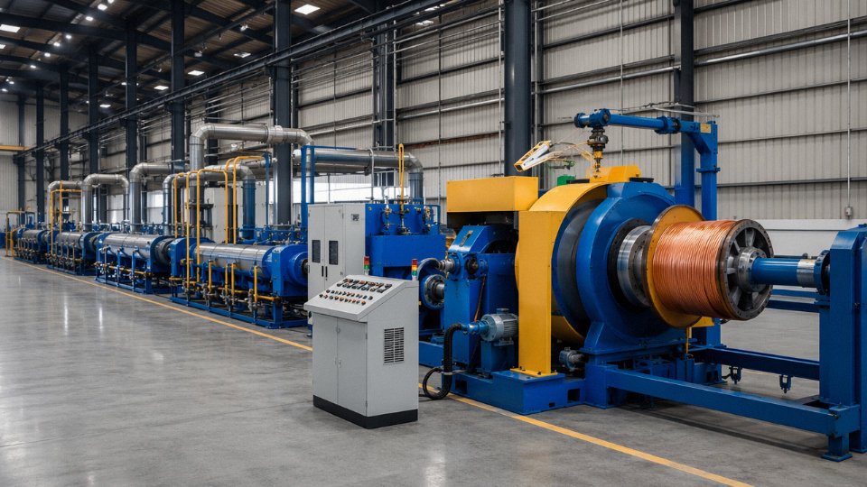
Rubber cable extrusion is meaningfully different from thermoplastic PVC production, and not every cable plant handles both well. Rubber-sheathed Type 4 cables require a vulcanization curing process — typically steam autoclave or continuous vulcanization (CV) tube — where temperature, pressure, and line speed interact to determine cross-link density and final compound hardness. Get it wrong and you get a sheath that either cracks at low temperature or goes soft and tacky in summer heat above 40°C. Jinda’s dedicated rubber extrusion lines run these processes separately from the thermoplastic lines, with in-line diameter gauging and post-cure spark testing as standard — not as optional quality steps.
Compound Development for Non-Standard Environments
Most cable plants buy their sheath compound from a compounder and work with whatever grades are in stock. In-house elastomeric compound development capability changes what’s possible for buyers with aggressive specifications — a copper mine running high-sulfur ore, an offshore platform with intermittent H2S exposure, a port environment where the cable sits in pooled seawater mixed with hydraulic fluid. Jinda’s R&D team formulates and tests custom sheath and insulation compounds against client-specified chemical resistance requirements, and because the compounding is done internally, the lead time on a non-standard specification is typically weeks rather than months. That is a real operational difference when a project is waiting on cable to commission.
Quality Management and Traceability
Jinda operates an ISO 9001-certified quality management system with an in-house high-voltage test laboratory capable of testing cables to 1.5× rated voltage per IEC 60245.True
ISO 9001 certification is a verifiable third-party audit outcome; IEC 60245 specifies routine voltage test requirements, and testing to 1.5× rated voltage is a standard acceptance criterion for this cable family.
The in-house test lab runs routine voltage tests on finished drums before they ship. Batch traceability is maintained so that any drum delivered to site can be linked back to its copper rod lot, compound batch, production date, and the specific test report generated for that drum. For procurement managers writing quality clauses into purchase orders, this is the kind of system detail worth asking for explicitly — not just a certificate, but a traceable chain from raw material to finished cable.
Third-party certification relationships with international bodies cover the key standards: IEC 60245-4, AS/NZS 1747 Type 4, BS 6708, IEC 60092 for marine applications, and applicable mining trailing cable standards. The technical team assists buyers in identifying the correct standard for their project’s regulatory jurisdiction — a genuinely useful service when a project spans multiple countries or when an importer needs a certificate of conformity aligned with local customs requirements.
Global Logistics and Export Documentation
Shipping to more than 50 countries builds real institutional knowledge about what documentation actually clears customs in different regions. Drumming is available in both metric and imperial sizes depending on buyer preference and end-country practice. For multi-cable project orders, consolidated shipment support reduces freight cost and simplifies receiving logistics on site. The export documentation team handles certificates of origin, test reports, and packing lists structured to match Letter of Credit requirements — which sounds administrative until the day a discrepancy holds up a shipment and a construction schedule slips.
Technical Support Before and After the Sale
Pre-sale consultation includes a free cable sizing review, datasheet comparison against project specifications, and a compliance gap analysis if the buyer is transitioning from one standard to another. For large mining or port installations, on-site or video-supported commissioning support is available. Warranty claims are handled through an engineering accountability process — not just a returns label. In practice, that means a technical contact who understands the application, not a generic customer service queue.