
Swap the neutral and line conductors on a 240 V feed and the equipment runs fine — right up until a technician touches the chassis during a fault and takes the full voltage through their hand. Get the ground conductor wrong, or omit it entirely to save a few cents on a cord assembly, and nothing looks broken until a ground fault sends fault current through whatever path it can find. That kind of incident shuts down a production line, triggers regulatory inspections, and generates liability exposure that dwarfs whatever was saved on materials. Understanding exactly what each of the three wires in a power cord actually does — not just which color it is, but what it carries, how much, and what fails when it’s wrong — is the starting point for specifying, procuring, and installing cords that don’t become failure modes.
A standard power cord contains three conductors: a live (or hot/active) wire that carries current to the load, a neutral wire that returns current to the source, and a protective earth (ground) wire that provides a low-impedance fault path back to the breaker. Color codes differ by region — brown/blue/green-yellow under IEC 60446, black/white/green under NEC, brown/light-blue/green-yellow under AS/NZS 3000 — but the function of each conductor is the same regardless of geography.
What makes this more than a wiring-colors quiz is the physics of what happens under fault conditions. The live and neutral carry working current continuously; the ground carries almost nothing during normal operation, yet it must be capable of handling hundreds of amperes for the fraction of a second it takes a breaker to clear a fault — and if it can’t, that energy goes somewhere else. That asymmetry between normal duty and fault duty is what most cord specifications get wrong, and it’s worth spending some time on.
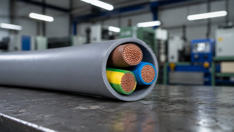
Live, Neutral, and Ground Defined: Electrical Roles and Physical Differences Inside the Cord
Understanding what each conductor actually does — not just what color it is — is the difference between a safe installation and one that passes inspection but fails dangerously under fault conditions. Let’s go through each wire in the order of risk.
The Live (Hot/Active) Wire
The live conductor carries alternating current from the supply at full line voltage: 120 V in North America, 230 V across most of Europe and Asia, sometimes 277 V or 480 V in industrial single-phase and three-phase branch circuits. It is energized the moment the supply is connected, regardless of whether the appliance switch is on. That last point matters more than most people act on — switching the neutral open leaves the live conductor sitting at full potential inside a “switched-off” device.
Color coding exists precisely because the live wire is the one most likely to kill you on contact. IEC 60446 mandates brown for single-phase live conductors; NEC installations use black (or red for a second hot leg); AS/NZS 3000 follows brown as well for the active conductor. Plug geometry reinforces this — IEC 60309 industrial plugs key the live pin so it cannot be inserted in the neutral or earth socket even in poor lighting. Mixing these up during re-termination is one of the most common causes of appliance chassis sitting at line voltage. Insulation on the live conductor under IEC 60227 is typically 0.6 mm wall thickness for 300/500 V-rated flexible cords, and 0.8 mm for 450/750 V class.
The Neutral Wire
Neutral completes the circuit, returning current to the source transformer at what is theoretically near-zero voltage relative to earth. The misconception that neutral is “safe to touch” has put maintenance workers in the hospital. Under balanced load conditions, neutral-to-earth voltage is low — often under 1–2 V at the outlet. But in a building with a heavily loaded or undersized neutral conductor, neutral-to-earth voltage can rise to 10 V, 20 V, occasionally higher, depending on the length and cross-section of the neutral run and the degree of phase imbalance. On a 230 V single-phase circuit that neutral is still part of a live loop; touching it while grounded completes a path. Treat it with the same respect as the live wire during any live-work procedure.
Color: blue (IEC/AS/NZS), white or grey (NEC).
The Ground (Earth) Wire — The One That Carries Nothing Until Everything Goes Wrong
Under normal operation, the ground conductor carries essentially zero current. Its entire purpose is fault management: it provides a deliberate low-impedance path back to the source so that when a live conductor contacts an appliance chassis, the resulting fault current is large enough to trip a breaker or blow a fuse in well under 100 milliseconds — typically 20–80 ms on a correctly coordinated circuit. That speed matters because the human let-go threshold is roughly 10 mA at 50/60 Hz, and ventricular fibrillation risk increases sharply above that. A high-impedance or absent ground path means fault current finds a human body instead.
Ground fault currents during a hard fault can reach several hundred amperes for those critical milliseconds — the ground conductor must handle that without burning open before the overcurrent device clears. This is why, in certain standards and heavier cord constructions, the ground conductor is specified one cross-section step larger than the line conductors, or at minimum equal to them.
Physical Construction Differences That Affect Procurement Decisions
For procurement engineers specifying flexible cords, these are not cosmetic details.
| Parameter | Live / Neutral | Ground / Earth |
|---|---|---|
| IEC 60227 insulation wall (300/500 V) | 0.6 mm nominal | 0.6 mm nominal (same class) |
| IEC 60227 insulation wall (450/750 V) | 0.8 mm nominal | 0.8 mm nominal |
| UL 62 (NISPT-2, 300 V) | 0.76 mm nominal | 0.76 mm nominal |
| Conductor sizing — heavy industrial cords | Matched to load current | Equal to or one step larger (e.g., 2.5 mm² line, 4 mm² earth in some IEC panel cord specs) |
| Stranding | Flexible class 5 or 6 | Same stranding class — do not substitute solid core in flexible cord |
The ground wire in a standard IEC flexible power cord carries no current during normal operation.True
IEC 60364 and basic circuit theory confirm the protective earth conductor is only active during fault conditions; under normal operation current flows through live and neutral only.
The stranding class restriction is worth emphasizing. Substituting a solid or semi-rigid conductor in a ground core of a flexible cord — sometimes seen when a supplier cuts costs on the earth wire specifically — will work fine on a test bench and fail by conductor fatigue within months of flexing in service. Class 5 or class 6 stranding per IEC 60228 is non-negotiable for flexible applications. Specify it explicitly in your purchase order, not just by referencing the cord type designation.
Global Wire Color Codes: IEC, NEC, AS/NZS, and Legacy Systems Side by Side
If you’re sourcing power cords across regions — which most of Jinda’s international customers are doing — wire color codes are not a formality. A maintenance technician who assumes “black is always neutral” because he trained in North America, then opens a panel wired to IEC 60446, is holding a live conductor he thinks is neutral. That’s how people die and how facilities rack up incident reports.
Here’s the reference table you actually need on your desk.
| Standard / Region | Live / Hot | Neutral | Ground / Earth | Typical Countries |
|---|---|---|---|---|
| IEC 60446 (post-2004) | Brown | Blue | Green-Yellow | EU, most of Asia, international OEM |
| UK legacy (pre-2004) | Red | Black | Green | Older UK installations |
| North America NEC | Black (hot 1), Red (hot 2) | White or Gray | Green or Bare | USA, Canada, Mexico |
| Australia / NZ AS/NZS 3000 | Brown (active) | Light Blue | Green-Yellow | Australia, New Zealand |
| China GB/T 6995 | Yellow-Green / Brown | Blue | Yellow-Green | Mainland China |
| Japan JIS C 3306 | Black | White | Green | Japan |
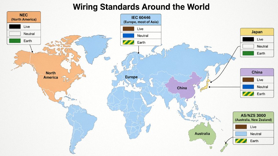
Why Harmonization Happened — and Why Legacy Colors Still Bite You
Before IEC 60446 was revised in 2004, European countries ran a mess of national conventions. The UK used red-black-green. Germany used grey or brown depending on the decade. Some Eastern European countries followed Soviet-era codes entirely. The 2004 revision pushed brown/blue/green-yellow as the unified international standard, partly to reduce exactly the kind of maintenance accident described above, and partly because pan-European manufacturing made it impractical to run country-specific cable lines.
The problem is that pre-2004 wiring doesn’t get ripped out just because a new standard drops. UK buildings wired before 2004 still use red as live and black as neutral, which is the direct inverse of what a German or Chinese-trained electrician would expect — black in IEC 60446 is not a conductor color at all for single-phase, but in the old UK scheme it’s neutral. In practice, any brownfield site in the UK, Australia, or continental Europe that hasn’t been fully rewired is a mixed-color environment. Maintenance teams need to verify at the terminal, not at the insulation.
IEC 60446 post-2004 mandates brown for single-phase live conductors across all EU member states.True
The 2004 revision of IEC 60446 standardized brown=live, blue=neutral, and green-yellow=earth for single-phase AC circuits, and EU member states incorporated this into national standards (e.g., BS 7671 in the UK for new installations from April 2006 onward).
Three-Phase and Multi-Core: The Same Foundation, Extended
Single-phase three-wire is the building block. When you move to three-phase, you’re adding one or two additional live conductors. Under IEC 60446, a four-core three-phase cable (no neutral) carries brown, black, and grey as the three phases, plus green-yellow earth. A five-core cable adds blue as neutral. NEC uses black, red, and blue for the three phases in a multiwire branch circuit, with white/gray neutral and green or bare ground.
The key operational point: ground and neutral colors remain anchored to their single-phase definitions even as you add phase conductors. If your procurement team is ordering five-core industrial cable from multiple regions to the same installation, the neutral and earth colors need to match — a blue neutral from IEC and a white neutral from NEC cannot both terminate in the same neutral bus without clear re-identification.
Procurement Warning: Cross-Region Imports and Color Compliance
This is where buyers genuinely get caught. Say you’re importing cords manufactured to GB/T specs — brown live, blue neutral, green-yellow earth — for installation in a North American facility. The colors happen to align with IEC 60446, but NEC Article 200 requires that white or gray identify the neutral conductor. Blue neutral is not NEC-compliant for permanently installed wiring without re-identification. You either need cords manufactured specifically to NEC, or you need to sleeve or re-tape the neutral conductor white at both terminations, documented in your installation record.
Going the other direction, IEC 60446 clause 5.3 requires that green-yellow earth conductors must not be used for any other purpose and must not be re-identified as another function. You cannot tape over a green-yellow conductor and press it into service as a phase. That sounds obvious, but field modifications on job sites happen, and they fail audits — and inspections.
In my experience, the cheapest mistake a procurement manager makes is buying cords to the most readily available regional spec, then discovering mid-installation that local inspectors won’t sign off. Lead time to re-order or re-sleeve a full container is rarely less than two to four weeks. Specify the destination-country color standard explicitly on your purchase order, not just voltage and current rating.
Conductor Sizing and Insulation Classes: How to Match Wire Gauge to Load Current and Environment
Getting the conductor cross-section right is one of those decisions that looks straightforward on paper and turns into a warranty claim — or worse, a fire — when the assumptions are wrong. Oversizing wastes material cost and makes cord sets unnecessarily stiff; undersizing causes resistive heating that degrades insulation over months before anything visibly fails. Neither failure mode announces itself politely.
Cross-Section Selection: Work Backward from the Load
Start with the appliance’s rated current, which for most equipment is stamped on the nameplate or given in the spec sheet. That number alone is not enough.
A worked example grounded in practice: a 2 kW industrial power tool running on a 230 V single-phase supply draws roughly 8.7 A at unity power factor — call it 9–10 A once you account for a realistic power factor around 0.9. A 1.0 mm² conductor handles that comfortably under ideal lab conditions, but the cord will be 10 meters long, bundled with other cables on the floor for part of its run, and operating in a factory bay where ambient temperature regularly hits 40–45°C in summer.
Voltage drop over 10 m of 1.0 mm² copper at 10 A works out to roughly 3.4 V — about 1.5% of 230 V, which is acceptable, but only just. Apply a bundling derating factor of around 0.75 (three or four cables laid together) and a temperature correction for 45°C ambient (factor roughly 0.87 under IEC 60245 methodology), and the effective ampacity of that 1.0 mm² conductor drops to somewhere in the 13–15 A range from its nominal ~17 A rating. You still have margin — but if duty cycle is continuous rather than intermittent, most experienced engineers bump to 1.5 mm² and stop worrying about it. The cost difference on a 10-meter cord is negligible.
AWG-to-mm² Reference and Ampacity Under Real Standards
| mm² | AWG equiv. | IEC 60245 ampacity (60°C) | IEC 60245 ampacity (75°C) | IEC 60245 ampacity (90°C) | Typical application |
|---|---|---|---|---|---|
| 0.75 | 18 AWG | ~6 A | ~8 A | ~10 A | Light appliances, table lamps |
| 1.0 | 17 AWG | ~10 A | ~13 A | ~15 A | Small power tools, kettles |
| 1.5 | 15 AWG | ~15 A | ~18 A | ~22 A | Household outlets, 16 A tool cords |
| 2.5 | 13 AWG | ~21 A | ~26 A | ~30 A | Industrial equipment, welders |
| 4.0 | 11 AWG | ~28 A | ~35 A | ~40 A | Heavy industrial, HVAC units |
| 6.0 | 10 AWG | ~36 A | ~46 A | ~52 A | High-draw machinery, compressors |
Ampacity figures here assume single-phase flexible cord in free air, PVC insulation unless noted. UL 62 ratings for the North American market follow a broadly similar pattern but use different correction tables — always check the applicable standard for the destination market, not just the manufacturing origin.
A 0.75 mm² conductor is sufficient for continuous 15 A loads in bundled industrial cordsFalse
Under IEC 60245, 0.75 mm² flexible conductor has a nominal ampacity of roughly 6–10 A depending on temperature class. Continuous 15 A loading would cause sustained overheating, insulation degradation, and eventual failure. At least 1.5 mm² is required for 15 A continuous service, and derating for bundling or elevated ambient temperature may push the requirement to 2.5 mm².
Insulation Material: PVC, Rubber, and TPE Are Not Interchangeable
PVC is the default for most cord sets — cost-effective, easy to extrude consistently, and rated to a conductor temperature of 70°C in standard formulations (up to 90°C in heat-resistant grades). Dielectric strength runs roughly 15–20 kV/mm for typical cable-grade PVC. The drawback everyone in industrial procurement eventually discovers: PVC stiffens noticeably below about 0°C and becomes brittle in sustained cold-store or outdoor winter environments. It also contains halogens, which matters for projects under LEED or specific facility specs.
Rubber and EPDM compounds handle that cold-flexibility problem well — EPDM-insulated cords remain pliable to around -40°C, resist oils and many industrial fluids, and survive the kind of dragging and kinking that destroys PVC cords in a few months on a busy plant floor. Dielectric strength for EPDM is typically 20–25 kV/mm. The trade-off is cost: EPDM compound costs more than PVC per kilogram, and the extrusion process requires tighter process control.
TPE — thermoplastic elastomer, various grades — is increasingly specified for green-building projects, consumer electronics with eco-labeling requirements, and export to markets that restrict halogenated materials. Dielectric strength varies by grade but generally falls in the 15–22 kV/mm range. TPE is also recyclable at end of life, which PVC simply is not in practical terms.
Jacket and Sheath: The Outer Layer Earns Its Keep
The outer jacket protects conductors from the environment, not from electrical stress. For industrial cords, Shore A hardness in the 75–90 range is a reasonable target for abrasion resistance without becoming so hard the cord cracks when bent around tight corners. UV-stabilized compounds are non-negotiable for any cord running outdoors or through skylighted areas; un-stabilized PVC can become brittle and cracked within one to two seasons of direct sun exposure, depending on UV intensity and climate.
Chemical resistance is plant-specific. Coolants, hydraulic fluids, and cleaning solvents each attack different polymer systems differently. A cord jacket that survives neat mineral oil may swell and soften rapidly in contact with ketone-based degreasers. If the application involves chemical exposure, request specific compatibility data from the cable supplier — a Shore A hardness spec alone tells you nothing about what happens after six months in a coolant mist environment.
Jinda’s flexible power cord portfolio spans conductor cross-sections from 0.5 mm² through 95 mm², covering standard PVC, heat-resistant PVC, EPDM, and halogen-free compound systems. That range is relevant because OEM appliance builders and large infrastructure projects have genuinely different needs — a 0.75 mm² appliance cord for a consumer product has nothing in common with a 35 mm² flexible supply cable for a packaging line drive, and a supplier whose manufacturing scope covers both ends of that spectrum can support sourcing consolidation in ways a narrow-range supplier cannot.
What Happens When One of the Three Wires Fails: Fault Scenarios, Shock Risk, and Fire Hazard Analysis
The three conductors in a power cord are not equally dangerous when they fail. Understanding which failure mode kills quietly, which causes immediate chaos, and which just stops your machine is the difference between a disciplined maintenance program and a reactive one.
Broken Live Wire: Annoying, but Not Harmless
A severed live conductor is the most forgiving failure in terms of immediate shock hazard — the appliance simply goes dead. Most technicians treat this as a straightforward repair. The underappreciated risk is what happens at the break point itself. A partial conductor failure, where some strands have broken but current still flows through a reduced cross-section, produces resistive heating and, under load cycling, intermittent arcing. In a flexible cord that flexes thousands of times near a strain relief — think a floor scrubber cable or a portable tool used daily — that arcing can carbonize PVC insulation and ignite it without ever tripping a breaker.
Stranded conductors handle flex fatigue dramatically better than solid wire, which is why IEC 60228 Class 5 and Class 6 flexible conductors are specified for portable equipment rather than Class 1 or 2 solid conductors. In practice, a 1.5 mm² Class 5 conductor in a properly supported cord can endure tens of thousands of flex cycles before failure; the same cross-section in solid wire would fracture far earlier and with much less warning. Bend radius compliance during installation matters here — violate the minimum bend radius at the entry to a machine cabinet and you’ve pre-fatigued the cord before it ever sees service.
Broken Neutral: The Failure That Kills Without Warning
This is the one that keeps experienced electricians cautious. In a 120/240 V North American split-phase system, a lost neutral doesn’t just drop half the circuit. The two 120 V legs, previously balanced across the neutral, now redistribute voltage based on the impedance of connected loads. A light load on one leg and a heavy load on the other can push voltage on the light-load side up toward 200 V or beyond — well above the rating of 120 V-rated equipment. Motors overheat. Electronics fail. In worst cases, fires start.
Three-phase systems behave similarly. Drop the neutral on a wye-connected system feeding single-phase 230 V loads and the unloaded phases can spike toward the full phase-to-phase voltage — roughly 400 V in a 230/400 V system — across equipment rated for 230 V. The failure happens fast and the damage is severe.
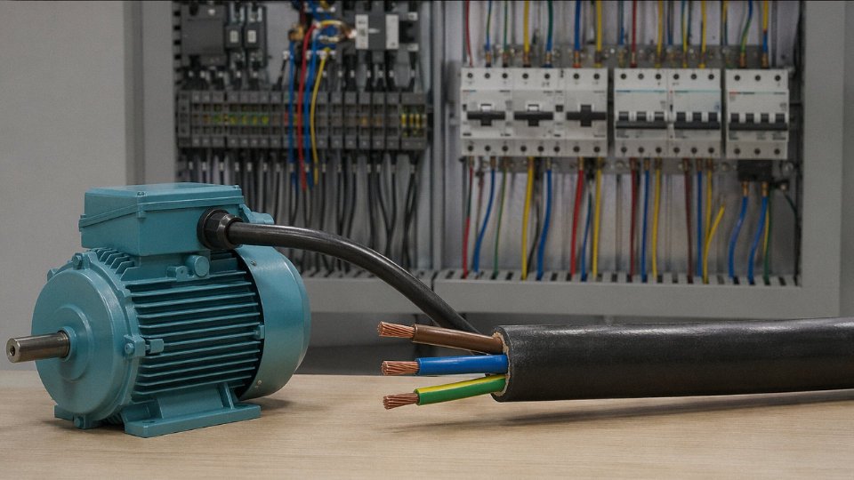
The mechanism is straightforward physics, but the reason fatalities occur is that the equipment may still appear to operate for a short period before catastrophic failure. Nobody suspects the neutral.
Broken Ground Wire: Silent Until It Kills
A disconnected ground is genuinely insidious because the appliance runs normally. Completely normally. Until the primary insulation between a live conductor and the metal chassis develops a fault — age, moisture ingress, mechanical damage, a pinched wire — at which point the chassis floats at line voltage. Anyone touching that chassis while standing on a grounded surface completes the fault path through their body.
A ground wire failure cannot be detected through normal appliance operation; it requires a dedicated ground continuity or ground-bond impedance test.True
The ground conductor carries no current under normal operation, so no functional symptom appears. Only a continuity test or a ground-bond impedance test per IEC 60950/62368 will reveal an open or high-resistance ground path before an insulation fault makes it lethal.
GFCI devices rated to IEC 60990 and UL 943 Class A trip at 4–6 mA leakage, which does provide a backup protection layer — but only if the GFCI itself is present and functional. Relying on a GFCI to compensate for a missing ground is not a design strategy; it’s an accident waiting for the right conditions.
Connector and Strain Relief Failures vs. Mid-Cord Fatigue
Mid-cord flex fatigue tends to develop gradually. Connector-end failures are often sudden and more likely to affect the ground conductor specifically, because of how strain relief works — or doesn’t work. The ground wire inside a molded or field-wired plug is typically the shortest of the three, intentionally, so it’s the last to pull out if the cord is yanked. But in worn or inadequate strain relief, the cord jacket moves relative to the terminals and the shortest wire takes the first abuse.
IEC 62368-1 specifies pull-force tests for strain relief: typically 50–100 N applied to the cord for 1 minute, depending on cord diameter and equipment class. Cords that fail this test in incoming inspection have almost always been assembled with undersized or improperly torqued strain relief clamps. This is a manufacturing quality issue, not a field installation issue, and it’s visible during receiving inspection if you bother to check.
What You Should Actually Test
For incoming inspection of power cords or finished equipment, three tests cover the critical failure modes. A simple continuity tester confirms all three conductors are unbroken end-to-end — takes about 30 seconds per cord. Insulation resistance testing at 500 V DC between each pair of conductors and between conductors and any shielding should read above 1 MΩ at minimum; values below 10 MΩ on a new cord warrant rejection. Ground-bond impedance testing per IEC 60950 or IEC 62368-1 requires the ground path resistance between the equipment earth terminal and any accessible conductive part to be 0.1 Ω or less — a threshold that a length of undersized ground wire, a corroded terminal, or a loose crimp can easily violate without being visually obvious.
Skipping these tests on the assumption that a cord looks fine is how latent failures reach the field.
International Safety Certifications for Three-Wire Power Cords: UL, VDE, HAR, CCC, and SAA Explained
Sourcing a power cord that works electrically is the easy part. Getting one that clears customs, satisfies your OEM customer’s compliance team, and actually carries the right certification mark — that’s where procurement gets complicated fast.
UL 62 and the Listed vs. Recognized Distinction (North America)
UL 62 covers flexible cords and cables sold into the North American market. The standard tests insulation resistance, conductor ampacity tables, and flame propagation — specifically the FT1 vertical flame test for general flexible cord and FT2/FT4 for harder-service constructions used in industrial environments. Passing FT4 is meaningfully more demanding; it involves a larger flame source and is required for some portable power tool cords.
The distinction that trips up buyers more than anything else: UL Listed versus UL Recognized. A UL Listed cord set — plug, conductors, and connector assembled — can be sold and used as a finished product. A UL Recognized component (the cord itself, without terminations) must be incorporated into a Listed end product before it’s compliant. If you’re buying bare cord stock to assemble in your factory, Recognized is the right mark. If you’re selling a finished appliance cord into Home Depot, you need Listed. Mixing these up delays FCC/ETL audits and creates real liability exposure.
HAR Mark: What That Print on the Jacket Actually Guarantees
The “ mark, administered through CENELEC under the HD 22 series standards, is a mutual recognition scheme covering all EU and EEA member countries. One national body tests and approves; all others accept it. In practice this means a cord approved by VDE in Germany or KEMA-KEUR in the Netherlands carries the HAR mark and ships legally into Italy, Poland, Spain — anywhere in the bloc.
What the HAR mark actually commits to: correct IEC 60446 conductor colors (brown live, blue neutral, green-yellow earth), insulation wall thickness within specified tolerances, and ampacity ratings verified against the relevant HD 22 part. The “ text is printed repeatedly along the jacket, which makes field inspection straightforward. If you’re receiving a shipment and the print is absent or the colors don’t match IEC 60446, that cord is not legitimately HAR regardless of what the paperwork says.
VDE: Why German Machine Builders Still Specify It Separately
VDE testing by VDE Prüf- und Zertifizierungsinstitut carries weight beyond the HAR baseline — tighter production audits, more frequent factory surveillance visits, and a brand reputation that German OEM machinery builders have trusted for decades. Specifying VDE on a cord sourced from Asia is common practice for mid-range and premium machine builders who need to demonstrate due diligence to their own industrial customers. It’s not legally required if HAR is present, but in practice a Siemens or Trumpf-adjacent supply chain will often ask for it anyway.
CCC Under GB/T 5023 and GB/T 5013
CCC (China Compulsory Certification) applies to cords sold or used inside China. GB/T 5023 covers PVC-insulated cables for rated voltages up to 450/750 V; GB/T 5013 covers rubber-insulated equivalents. For a manufacturer like Jinda, operating five production bases domestically, CCC is baseline for any cord destined for the Chinese market. Export-only production runs can be structured under the relevant IEC or UL tooling without CCC, which avoids unnecessary testing cost — but the production line documentation must clearly separate domestic and export batches, because mixing them creates audit problems during SAMR inspections.
CCC certification is required for power cords manufactured in China that are sold within the Chinese domestic marketTrue
China's Compulsory Certification system, administered by CNCA, mandates CCC marking for covered electrical products sold domestically. Export-only products are not legally required to carry CCC, though manufacturers must maintain clear production and documentation separation.
SAA, PSE, and KC: Minimum Knowledge for Each Market
SAA (Australia/New Zealand) certifies against AS/NZS 3112 for plugs and AS/NZS 3191 for flexible cords. The distinguishing requirement most buyers miss: the active conductor must be brown (not black), and the SAA mark must be held by the Australian or New Zealand responsible supplier, not the overseas factory. Budget 8–14 weeks for initial approval, depending on the certification body’s queue.
PSE (Japan) splits into two tiers — the diamond PSE mark for specified electrical appliances under the Electrical Appliances and Materials Safety Act, and the circle PSE for non-specified. Flexible cord typically falls under specified appliances. Testing requirements include insulation breakdown voltage and abnormal temperature rise tests that are somewhat more conservative than IEC equivalents at lower conductor cross-sections.
KETI/KC (South Korea) under the Electrical Appliances Safety Management Act requires KC marking. Conductor color requirements broadly follow IEC conventions, which simplifies things if you already have HAR-approved construction, but the KC application requires a Korean Registered Conformity Assessment Body and a local agent — you can’t self-declare.
Stacking Certifications: Getting One Cord to Cover Multiple Markets
Global OEMs routinely need a single cord construction that satisfies UL, HAR, and CCC simultaneously. This is achievable but requires deliberate design. The conductor color conflict is the main obstacle: NEC black/white/green versus IEC brown/blue/green-yellow. The practical solution most experienced cord manufacturers use is a dual-approved jacket print — “ text on the jacket with IEC conductor colors, combined with UL Recognized component approval on the same construction. The UL Recognized approval accommodates non-standard colors when accompanied by clear appliance-level marking at the end product. CCC can typically be layered onto the same physical construction since GB conductor color requirements for export-adjacent lines are flexible with proper documentation.
The real constraint is insulation wall thickness — UL 62 and HD 22 don’t always agree on minimums for the same cross-section, so the cord must meet the more demanding of the two. In practice, for 1.5 mm² three-core cord this usually means targeting the UL wall thickness, which satisfies HAR as well. Getting this dialed in upfront, before tooling is cut and samples are submitted, saves roughly two to four months of back-and-forth with testing labs.
Three-Wire Cord Selection for Specific Industrial Applications: Motors, HVAC, Data Centers, and Portable Tools
Generic wiring articles stop at color codes and conductor sizing formulas. On the plant floor, that’s not enough. The application dictates everything — jacket chemistry, strand architecture, ground conductor spec, even how the cord is terminated. Here’s how the three-wire structure plays out across four demanding environments.
Motors and Variable-Frequency Drives
Inrush current on a direct-on-line motor start can hit six to ten times the full-load ampere rating for the first few hundred milliseconds. That transient alone argues for sizing the live and neutral conductors one or sometimes two cross-section steps above what steady-state load math would suggest — particularly on motors above 7.5 kW where that inrush duration stretches long enough to heat a borderline conductor.
VFD applications introduce a different problem that catches a lot of engineers off guard. The drive’s switching frequency generates high-frequency ground currents that can reach tens of milliamps on longer cable runs. A standard stranded ground conductor handles 50 Hz fault current fine but presents enough inductance at 4–16 kHz to impede those high-frequency currents, which then look for lower-impedance return paths — sometimes through bearing races, sometimes through signal cables, neither of which you want. The fix is a dedicated equipment grounding conductor using bare or green-yellow stranded copper at ≥99.9% IACS conductivity, with the tightest possible lay and the shortest practical run back to the drive’s PE terminal. Twisted or braided ground configurations in the cord construction help considerably on runs over roughly 10 meters.
HVAC and Refrigeration Equipment
Outdoor compressor units experience UV degradation, ozone, and often refrigerant oil mist — conditions that will crack a standard PVC jacket within two to four years depending on climate and refrigerant type. Specify UV-stabilized jacket compounds (chlorinated polyethylene or polychloroprene are common choices) and confirm the refrigerant compatibility explicitly, because HFO-based refrigerants have different solvent characteristics than the older HCFCs and can soften some PVC formulations faster than expected.
Vibration is the other silent killer here. A compressor running at 1,450–2,900 RPM transmits enough mechanical energy into cord connections that a low-strand-count conductor work-hardens and fractures at the termination point, sometimes within 18 months. Class 5 or Class 6 flexible conductors per IEC 60228 — typically 196 strands or more in a 2.5 mm² section — handle this significantly better than Class 2 rigid conductors, even if both pass the initial current rating.
Data Center Power Distribution
The 80% continuous load derating rule is non-negotiable in data center design — a 16 A circuit should carry no more than roughly 12–13 A sustained. Where this bites procurement teams is in cord specifications for floor-level PDU connections: the actual cord current rating must account for bundling derating on top of the 80% rule, which can push you from 1.5 mm² to 2.5 mm² even on relatively modest server loads.
In TN-S distribution systems, the ground conductor resistance matters beyond just fault-clearing. High ground path impedance in a densely patched environment contributes to ground potential differences between adjacent equipment chassis — enough to cause communication errors or corrupt sensitive measurements. Keep ground conductor resistance low and verify it; don’t assume it.
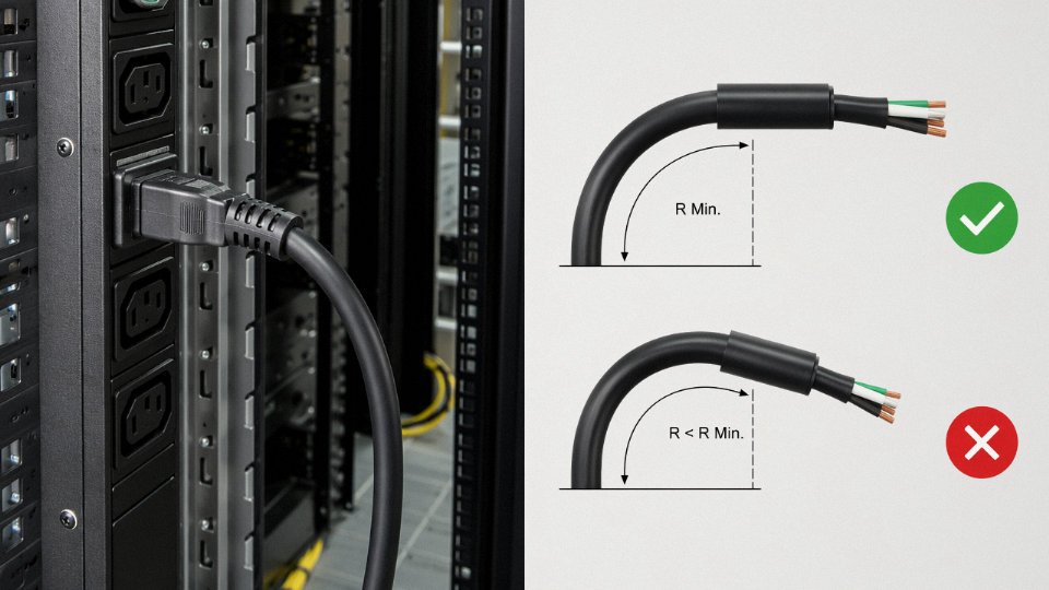
Bend radius is a practical headache nobody writes about. High-density floor PDU installations often force cords into 180° bends in tight trays. Minimum bend radius for flexible power cords is typically 6–8× the overall cord diameter, and violating that consistently fatigues conductors at the bend point.
Portable Electric Tools
IEC 60884-1 and UL 817 both specify cord-set construction requirements, but the detail that trips up procurement is the IEC 60745 minimum ground conductor requirement: 1.0 mm² for tools up to 16 A, regardless of how small the live/neutral conductors are. Undersizing the ground to save cost or reduce cord stiffness is a compliance failure and a shock hazard.
Strain relief classification — X-type (non-replaceable, cord destroyed on removal) versus Y-type (replaceable without special tools) — affects both the cord attachment design and the end-user maintenance scenario. Portable tools in rough environments often benefit from Y-type attachment so a damaged cord can be replaced in the field rather than scrapping the tool body.
Medical Equipment
This is where cord selection becomes genuinely unforgiving. IEC 60601-1 requires that ground resistance measured from the mains plug earth pin to any patient-accessible conductive part not exceed 0.2 Ω — that’s the entire ground path, including cord, connectors, and internal bonding. In practice, the cord alone needs to land well under 0.1 Ω to leave margin for connector contact resistance and aging.
Hospital-grade power cords in North America must carry a green dot marking visible on the plug body, indicating they meet UL 817 and NEMA requirements for hospital-grade cord sets.True
The green dot is a recognized marking for hospital-grade plugs in North America, indicating compliance with UL 817 and applicable NEMA standards for use in patient care areas. It is distinct from general commercial cord sets and is required by some facility standards and the NEC for patient care vicinity receptacles.
Leakage current limits under IEC 60601-1 (typically 500 µA for Class I applied parts in normal condition) mean that ground conductor integrity is not just a fault-clearing question — it’s a continuous operating requirement. A corroded or intermittent ground connection that would merely trip a GFCI in an office environment can push a medical device out of leakage compliance during normal use, with a patient in contact. Specify medical-grade cord sets explicitly; they are not interchangeable with standard industrial cords even when the connectors happen to fit.
Frequently Asked Questions About the Three Wires in a Power Cord
Can I cut off the ground prong to make a three-prong appliance fit a two-slot outlet?
No. Full stop. Removing the ground prong leaves the equipment enclosure unprotected — if a live conductor internally contacts the chassis, there is no low-impedance path to trip the breaker, and the enclosure sits at line voltage until someone touches it. NEC 110.3 prohibits using equipment in a manner inconsistent with its listing, and IEC 61140 requires that Protection Class I equipment maintain its earth connection throughout service life. In industrial settings the liability exposure is significant: if an inspector finds a modified cord after an incident, the facility’s insurance carrier has grounds to contest the claim. The correct fix is a proper outlet upgrade or a listed adapter — not a modified cord.
Why does the ground wire sometimes look thicker than the live and neutral conductors in a heavy-duty cord?
Because it may need to carry full fault current — potentially hundreds of amperes — for the milliseconds it takes the overcurrent device to clear. During a hard ground fault, the ground conductor is not carrying a small leakage current; it is temporarily the return path for a near-short-circuit. IEC 60364 and NEC 250 both permit the protective earth conductor to be sized equal to the line conductors, and in large cross-section cords (roughly 16 mm² and above) some standards actually require it. So if you open a 32 A industrial supply cord and the green-yellow wire looks the same gauge as the brown, that is intentional engineering, not a manufacturing error.
If the ground wire carries no current in normal operation, does its resistance actually matter?
Critically. IEC 62368-1 and UL 991 both require the ground path impedance to be ≤0.1 Ω, and the reason is arithmetic: fault current equals line voltage divided by total fault-loop impedance. A high-resistance ground path — corroded terminations, an undersized conductor, a loose crimp that passed visual inspection — raises that impedance, lowers the fault current, and the breaker may never trip. The enclosure remains energized. A 4–6 mA GFCI (per UL 943 Class A) will catch personal-contact leakage, but it does not substitute for a solid low-impedance ground path in equipment protection.
What does the marking “H05VV-F” or “H07RN-F” on a European cord jacket actually mean?
These are HAR harmonized cable designations and they are worth reading rather than ignoring. The H prefix means harmonized across European member states. The number — 05 or 07 — encodes the voltage rating: H05 is rated 300/500 V, H07 is 450/750 V. The first letter after the number indicates insulation material (V = PVC, R = rubber/elastomer). The second letter is the outer sheath material (another V for PVC, N for polychloroprene). The F means flexible stranded conductors. So H07RN-F is a rubber-insulated, polychloroprene-sheathed, flexible cord rated 450/750 V — typically specified for outdoor, welding, or heavy industrial use where H05VV-F would be inadequate. Specifying the wrong HAR designation is a common procurement error on European equipment projects.
How do I verify the ground conductor in a purchased cord is actually continuous?
A basic ohmmeter check end-to-end is a reasonable first screen — you are looking for less than 0.1 Ω, usually well under that on a properly made cord. For more rigorous incoming inspection, a ground-bond test per IEC 60884 or UL 817 injects 25 A AC through the ground path and measures voltage drop to confirm impedance stays within limits under load. When evaluating a supplier, ask for the factory test report format: it should show individual cord serial or batch traceability, not just a generic certificate.
Wire color alone reliably identifies conductor function in any power cordFalse
Color coding is region- and era-specific, and aged insulation discolors. Always verify with a voltage tester for live identification and a continuity test to earth for neutral/ground confirmation before working on any unfamiliar cord.
Does wire color alone tell me which conductor is which?
Not reliably, especially in aged or non-standard cordage. Insulation discolors over years of heat cycling, UV exposure, or chemical contamination. Pre-1970s British wiring used red for live and black for neutral — the opposite of what black means in North American NEC practice. Always confirm with a voltage tester first to identify the live conductor, then use continuity to a known earth reference to separate neutral from ground. Sourcing from certified suppliers with documented color compliance to IEC 60446 or regional equivalents gives you a meaningful baseline, but field verification before any maintenance work is non-negotiable.
Why does a power drill sometimes have only two prongs — is that safe?
Yes, under the right conditions. A Class II appliance under IEC 61140 achieves equivalent protection through reinforced or double insulation rather than an earth connection — two independent insulation barriers between live parts and anything touchable. The double-square symbol on the nameplate confirms this. Many handheld power tools and some consumer electronics are legitimately Class II, and the design is well-engineered for portable equipment where ground continuity through a flexible cord is harder to guarantee. The limitation: Class II construction is generally not appropriate for large stationary equipment with conductive enclosures, anything with internal transformers running at line voltage, or industrial machinery where fault energy is high enough that double insulation alone is a questionable sole safeguard. When in doubt on industrial procurement, specify Class I equipment with a verified ground conductor.
How to Source Three-Wire Power Cords for Bulk Industrial and OEM Projects: Quality Checkpoints and Supplier Evaluation
Knowing what the three wires do is half the job. The other half is making sure the cord you actually receive — in a container shipment six weeks from now — matches what the datasheet promised. That gap between spec and reality is where most sourcing problems live.
Factory Audit Checkpoints That Actually Matter
Start with copper purity. A conductor that measures the right cross-section but uses substandard copper alloy or even copper-clad aluminum will run hotter and fail sooner under continuous load. Ask for EDX (energy-dispersive X-ray) or ICP-OES test results confirming conductor copper content above 99.9% IACS. Reputable manufacturers run this on incoming rod stock; if a supplier hesitates or offers only their own in-house word, that’s a red flag worth noting before you commit to 50,000 meters.
Cross-section verification is where a micrometer alone isn’t enough. The weight-per-meter method — weighing a one-meter sample, dividing by conductor density, comparing against the nominal area — catches the “thin-stranded” trick where more air gaps than copper fill the bundle. Combine it with a direct micrometer check on individual strands. A 1.5 mm² cord that actually delivers 1.3 mm² will run close to its thermal limit on any sustained load near the rated current, shortening insulation life measurably.
Insulation wall thickness per IEC 60811 strip-test procedure is straightforward but often skipped. The test requires peeling a short section of insulation and measuring wall thickness at the thinnest point under magnification. Minimum values are construction-specific; the number to care about is the minimum, not the average. Corners get cut at the thinnest point.
Batch Documentation You Should Request Before Releasing Payment
Routine test reports under IEC 60227-1 or IEC 60245-1 should include spark test pass records (typically 4–6 kV AC for PVC-insulated flexible cord), conductor DC resistance per meter at 20 °C, and insulation resistance values — all per production lot, not just per design. Type test certificates for flame propagation (IEC 60332-1-2 at minimum for most industrial applications) and cold-bend performance matter especially for cords used outdoors or in cold-storage facilities where PVC stiffens unpredictably below roughly −5 °C to −15 °C depending on plasticizer formulation.
Third-party certification body test reports — UL, VDE, SAA, whatever your target market requires — should reference the exact construction you’re buying, not a similar one. Verify the certificate scope matches conductor cross-section, jacket material, and temperature rating of your specified cord.

Jinda's five integrated production bases in China provide full supply chain traceability from copper rod mill through compounding to finished cord.True
Vertically integrated cable manufacturers with in-house copper rod drawing and compound mixing can provide mill certificates and batch records at each stage; this is verifiable during a factory audit by requesting batch traceability documentation tied to a specific production lot number.
MOQ, Lead Time, and What Drives Each
Standard flexible cord constructions — your 0.75 mm² to 2.5 mm² PVC/PVC three-core types — typically carry MOQs in the 500–2,000 meter range per construction per color scheme, and lead times of roughly 2–4 weeks from stock or fast-turn production runs. Custom constructions with special insulation (XLPE, rubber, halogen-free compound), unusual cross-sections above 4 mm², or non-standard jacket colors run 8–14 weeks realistically, sometimes longer if the insulation compound needs a dedicated compounding batch. Plan around that window; OEMs who don’t often end up expediting at significant premium.
Long-Term Partnership Factors
For high-volume OEM programs, the transactional price per meter matters less over time than a few structural capabilities: can the supplier provide application engineering input during cord design — cable flex radius, torsion cycle testing, connector compatibility — before you’ve tooled a product? Can they run joint qualification testing on a new construction alongside your own lab? Consignment inventory arrangements, where the supplier holds finished stock against a rolling forecast and you pull against it, meaningfully reduce your working capital exposure on commodity cord SKUs.
Jinda’s integrated R&D-to-after-sales model, serving customers across 50-plus countries from five production bases, is structured specifically to support this kind of long-term industrial and OEM relationship rather than spot transactions. In practice, that means a single technical contact who knows your application, not a rotating sales desk.




