Swap the wrong plug adapter on a production line or hand the wrong connector spec to a procurement team, and the consequences stack up fast — a machine that won’t power on, a shipment held at customs because the plug format doesn’t match the destination country’s socket standard, or worse, an arc fault from a connector rated at 10 A being pushed to 16 A. These aren’t edge cases. They happen on real floors, and they’re almost always traced back to someone assuming plug-and-socket compatibility instead of verifying it.
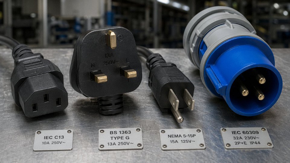
The device used to plug in a power cable is called a power connector or power plug — a male connector attached to or molded onto the cable end that inserts into a matching female socket or outlet. Depending on application, this can be a country-standard wall plug (Type A, B, G, and others), an IEC 60320 appliance coupler (such as a C13 or C19), or an industrial connector to standards like IEC 60309.
What makes this genuinely complicated isn’t the connector itself — it’s that over 15 distinct plug and socket systems exist globally, IEC 60320 alone spans 11 coupler pairs across a current range of 2.5 A to 16 A, and the mechanical insertion force required to seat a connection properly runs anywhere from 15 N up to 45 N depending on contact material and connector geometry. Get any one of those variables wrong and you’re either pulling a plug that won’t stay seated or forcing a fit that deforms the contacts on the first cycle.
The Anatomy of a Power Cable Connector: Plugs, Sockets, and Inlets Explained
The terminology here trips up procurement teams more often than you’d expect, and a mislabeled purchase order can mean weeks of delay or a pile of parts that won’t mate with anything on your production floor. So let’s be precise.
Plug, Socket, Inlet, Coupler — Not Interchangeable
A plug is the male connector, cord-mounted or device-mounted, with protruding pins or blades that insert into a receiving part. A socket (also called an outlet or receptacle) is the female, wall- or panel-mounted counterpart that accepts the plug — it doesn’t move; the power comes to it. An inlet is also female, but it lives on the equipment chassis itself: think of the IEC C14 inlet on the back of virtually every desktop power supply or rack PDU. You plug an IEC C13 cord-end into it. That cord-end connector is technically a coupler — a female connector that joins two cord sections rather than terminating at a wall or piece of equipment. The IEC 60320 C13/C14 pair is probably the most common example in industrial and IT environments globally, but the same logic applies across the C1–C22 series, which spans voltage ratings from 70 V up to 250 V AC and current ratings from roughly 2.5 A to 16 A depending on the specific series.
Confusing “inlet” and “socket” in a spec sheet is a genuine procurement error, not just a vocabulary quibble. One is fixed infrastructure; the other is an equipment-mounted feature you’re buying with the device or sourcing separately as a panel component.
Internal Anatomy: What’s Actually Inside the Housing
Crack open a well-made IEC C13 connector and you’ll find several distinct systems working together. The contact pins or blades carry current — these are the heart of the assembly. Around them sits the insulating housing, typically a glass-filled nylon or polycarbonate body, which provides dimensional stability and dielectric separation between conductors. At the rear, a strain relief (sometimes a separate rubber boot, sometimes integral to the housing) transfers mechanical load from the cable to the housing rather than letting tension pull at the terminal connections. Inside, individual conductors attach via cable clamps or screw terminals, and the whole assembly depends on maintaining consistent contact pressure over years of insertion cycles.
The earthing contact — the ground pin — is deliberately longer than the live and neutral contacts in most standards-compliant designs. This means earth engages first on insertion and releases last on withdrawal. In practice, this ensures the equipment chassis is bonded to ground before any live voltage is present at the circuit, and it stays grounded for a fraction of a second after live conductors disconnect. It’s a simple mechanical safety sequence, and any connector design that compromises that sequencing is a genuine hazard.
Contact Materials: Where Heat Problems Usually Start
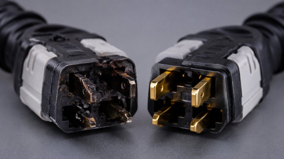
Brass is the standard base metal for contact pins across virtually all commercial and light industrial connectors — reasonably conductive, machinable, cost-effective. Most general-use connectors carry a tin or nickel plating over the brass, which resists oxidation and maintains acceptable contact resistance through hundreds of mating cycles. For high-cycle industrial applications or where contact resistance budgets are tight, silver or gold plating becomes relevant. Gold especially, in low-current signal-adjacent power connectors, prevents the surface oxidation layer that tin develops over time. That oxide layer matters because contact resistance directly drives I²R heating at the interface. A degraded tin-plated contact running 16 A in an enclosed housing can generate localized heat that slowly damages the insulation — not a dramatic fault, just slow deterioration that eventually shows up as a discolored connector or an unexplained nuisance trip.
The IEC 60320 C13/C14 connector pair is rated for up to 250 V AC and 10 A in most national variants, with a 16 A variant (C19/C20) designed for higher-load applications.True
IEC 60320 defines the C13/C14 pair at 250 V / 10 A for general use; the C19/C20 pair handles 250 V / 16 A, which is why data center PDUs typically use the larger format for high-draw server connections.
Termination Methods: Screw, Crimp, IDC, or Solder
How the conductor attaches inside the plug matters more than most buyers check. Screw terminals are the traditional field-wirable option — accessible, re-workable, but dependent on correct torque and prone to loosening under vibration. Crimp ferrules (pin or bootlace ferrules on stranded wire before screwing down) improve that significantly. IDC (insulation displacement contact) terminations are fast in manufacturing environments but generally not re-workable in the field without special tooling. Soldered terminations offer very low resistance and are stable in high-vibration environments, though they’re essentially permanent and depend heavily on workmanship quality — a cold solder joint is worse than a properly torqued screw terminal, not better.
IP Ratings on Connector Housings
For indoor dry environments — most commercial buildings, standard factory floors — IP20 connector housings are entirely adequate and represent the bulk of what’s installed globally. Once you introduce washdown areas, outdoor runs, or submersible pump applications, the housing design changes substantially: sealing gaskets, threaded coupling rings, overmolded cable entries. IP44 handles splash; IP65 covers directed water jets; IP67 and IP68 are for temporary or continuous immersion respectively. The tradeoff is always insertion cycle resistance vs. sealing integrity — a tight IP68 gasket seal adds to the mating force required, which in high-cycle automated equipment can matter for actuator sizing and wear rates. Insertion force for standard connectors already ranges from roughly 15 N to 45 N depending on connector type, contact material condition, and plating wear; add a compression gasket and you’re at the upper end or beyond.
Global Plug and Socket Standards: Which System Controls Your Power Connection
There are over 15 distinct plug and socket systems in active commercial use worldwide. That number surprises most procurement teams the first time they try to specify a cable assembly for simultaneous deployment across three continents. Getting this wrong doesn’t just mean a delay at customs — it can mean live pins exposed to touch, arcing inside undersized sockets, or a field return program that costs more than the original contract.
The Major Wall Outlet Systems
Type A (NEMA 1-15) is the standard two-pin unpolarized outlet across most of North America and Japan, though Japan runs at 100 V/50–60 Hz rather than the North American 120 V — a meaningful difference for motor-driven equipment. No ground pin. Common on older residential infrastructure and still specified on lower-power consumer products.
Type B (NEMA 5-15) adds the round ground pin below the two flat blades. Standard in the US, Canada, and Mexico. The 15 A/125 V rating suits most household and light commercial loads. You’ll find 20 A variants (NEMA 5-20) in commercial kitchens and medical environments where the horizontal slot on one receptacle blade lets you identify the circuit rating at a glance.
Type C — the Europlug — is two round pins, 2.5 A or 16 A versions, no ground. It physically fits Type E and Type F sockets, which is intentional: the CEE 7/4 (Schuko) and CEE 7/5 French standards accept it as an ungrounded fallback. That convenience has a consequence: a grounded piece of equipment shipped with a Type C cord loses its safety ground entirely. Worth calling out explicitly on any product safety checklist.
Type G (BS 1363) is the UK system, and it’s the one that consistently catches engineers off guard. The plug is fused — typically 3 A or 13 A — inside the plug body itself. That fuse is the first overcurrent protection device in the circuit, not the building breaker. The socket has a shutter mechanism that opens only when the longer ground pin engages first. Used across the UK, Hong Kong, Malaysia, Singapore, and parts of the Middle East. If you’re supplying cord sets for those markets, the fuse rating must match the cable’s current capacity, not just the appliance nameplate. I’ve seen batches shipped with 13 A fuses on 0.75 mm² cable — technically unsafe and increasingly flagged by UKCA audits.
Type I covers Australia, New Zealand, and — in a slightly different pin angle variant — China (GB 2099.1). The angled flat-pin geometry differs between the Chinese and Australian versions enough that a Chinese plug fits an Australian socket loosely and should not be treated as interchangeable under any compliant installation.
Type H (Israel, SI 32) uses three pins in a Y-pattern and is unique to the Israeli market. Type N (Brazil, NBR 14136) was introduced to replace the mixed Type A/B/C legacy mess Brazil had been running for decades. The 10 A and 20 A versions are dimensionally different — check pin diameter before ordering.
IEC 60320 Appliance Couplers: The Equipment Side of the Connection
While wall socket standards govern the building interface, IEC 60320 governs the detachable connection between a power cord and equipment. This is the series procurement teams actually specify most often.
C13/C14 is the ubiquitous IEC connector on IT equipment, monitors, and AV gear. Rated 10 A, 250 V, operating temperature up to 70°C on standard versions (higher-temp variants exist for industrial enclosures). The C14 is the male inlet on the equipment; C13 is the female on the cord. They’re so widespread that most data center engineers treat them as generic — which leads to problems when someone swaps in a 10 A cord on a 15 A UPS output circuit.
C19/C20 handles heavier loads: 16 A at 250 V. Used on high-density server racks, large UPS units, and PDUs where C13 would be undersized. The connector geometry is deliberately different from C13/C14 so the two can’t be mated accidentally.
C5/C6 — the “Mickey Mouse” connector — is the three-pin polarized coupling found on laptop power bricks and some portable appliances. Rated 2.5 A, 250 V. The polarized shape ensures line and neutral are correctly oriented. Small, but the current rating is a real limit; I’ve seen aftermarket laptop adapters with C6 inlets that run warm because the cord set was borderline undersized for a high-wattage adapter.
Insertion force across the IEC 60320 range typically runs 15 N to 45 N depending on contact material (brass vs. phosphor bronze), plating thickness, and number of mating cycles accumulated. A coupler at the high end of that range after thousands of cycles in a test lab environment usually signals worn contacts rather than a tight new connector.
IEC 60320 C13 and C19 connectors are interchangeable because they look similarFalse
C13 is rated 10 A and C19 is rated 16 A; their geometries are intentionally different to prevent cross-mating. Using a C13 cord on a 16 A circuit is an undersizing risk and violates IEC 60320 application guidelines.
Industrial Connectors: IEC 60309 and NEMA Locking Series
Standard outlet systems aren’t adequate for plant-floor or construction-site use. Vibration, accidental cord tension, and wet environments all demand something with positive retention.
IEC 60309 (commonly called CEE or “ceeform” in Europe) solves this with a round, keyed, locking body. The color coding is standardized: yellow for 110 V (common on UK construction sites as a reduced-voltage safety measure), blue for 230 V single-phase, red for 400 V three-phase. The key position — the angle of the grounding pin — also changes by voltage, so physical misconnection between voltage levels is blocked by geometry, not just color. The locking collar twist-locks the plug into the socket, which means a cable can’t fall out under load or be pulled free by cord weight alone. In foundry or outdoor environments, that’s not a nice-to-have.
NEMA locking connectors serve the same function in North American industrial and generator applications. The L5-30 (30 A, 125 V), L6-20 (20 A, 250 V), and L14-30 (30 A, 125/250 V four-wire) are the most common configurations. The twist-lock mechanism — curved blade pins that rotate into a captured position — holds against pull forces that would yank a standard NEMA 5-15 straight out of its socket. Generator rental companies almost universally specify L14-30 for portable generator connections because it maintains both hot legs plus neutral and ground in a single locked connector.
Reference Table: Major Connector Types at a Glance
| Connector / Standard | Voltage Rating | Current Rating | Grounding | Typical Application | Primary Markets |
|---|---|---|---|---|---|
| Type A / NEMA 1-15 | 125 V | Up to 15 A | None | Consumer electronics, lamps | USA, Canada, Japan, Mexico |
| Type B / NEMA 5-15 | 125 V | 15 A | Yes (round pin) | General appliances, computers | USA, Canada, Mexico |
| Type C / CEE 7/16 | 250 V | 2.5 A or 16 A | None | Ungrounded consumer devices | Europe, South America, Asia (widely) |
| Type G / BS 1363 | 250 V | 13 A (fused) | Yes (shuttered) | All domestic/commercial appliances | UK, HK, Malaysia, Singapore, ME |
| Type I / GB 2099.1 / AS/NZS 3112 | 250 V | 10 A or 15 A | Yes | Appliances, equipment | China, Australia, New Zealand |
| Type N / NBR 14136 | 250 V | 10 A or 20 A | Yes | All equipment (phased rollout) | Brazil |
| IEC 60320 C13/C14 | 250 V | 10 A | Via cord (IEC) | IT equipment, monitors, AV gear | Global (equipment level) |
| IEC 60320 C19/C20 | 250 V | 16 A | Via cord | Server racks, UPS, PDUs | Global (high-current equipment) |
| IEC 60309 (CEE) | 110–400 V+ | 16–125 A | Yes (keyed) | Industrial, construction, marine | Europe, global industrial |
| NEMA L14-30 | 125/250 V | 30 A | Yes (4-wire) | Generators, industrial panels | USA, Canada |
Interoperability Risks That Actually Cause Failures
Physical fit does not mean electrical compatibility. A Type C Europlug fits into a Type E (French) or Type F (Schuko) socket without an adapter — that’s by design, and it works safely for ungrounded loads. But that same Type C plug also fits loosely into some Type B sockets, with nothing stopping it from making partial contact on one pin.
The more dangerous scenario is adapters used across voltage zones. An Australian Type I plug on a European 230 V circuit via a cheap travel adapter — the plug geometry may fit the adapter body, but pin depth, socket shutter depth, and the voltage itself combine to create a real shock or fire risk. The pin depth mismatch means contact can be partial, increasing resistance at the interface, which means heat. Seasonal humidity changes in markets like Southeast Asia accelerate oxidation on exposed pin contacts and make partial-contact events more frequent in the field.
For procurement teams specifying cables for multi-market distribution: the cleanest approach is market-specific cord sets with a common appliance-side coupler (C13/C14 or C19/C20 at the equipment, country-specific plug at the wall end), rather than universal adapters. It adds SKU complexity, but it eliminates the field failure mode entirely.
How Power Cable Construction Determines Connector Compatibility
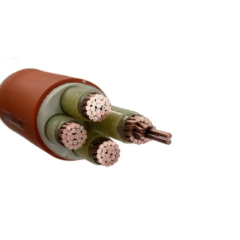
The connector doesn’t exist in isolation. Every dimension of a power cable — conductor cross-section, core count, insulation chemistry, flexibility class, jacket material — either opens or closes the door to a given connector family. Get the pairing wrong and you’re looking at overheating terminations, failed inspections, or a cable that physically won’t fit through a connector’s cable entry. These aren’t edge cases; they come up constantly in procurement when someone specifies a cable and a connector from separate datasheets without checking that the two were designed to meet.
Conductor Cross-Section Sets the Current Floor
Start here, because everything else is secondary if the conductor can’t carry the load. As a rough field guide: 0.75 mm² handles lighting circuits up to around 6 A, 1.5 mm² is the standard for 16 A circuits (wall outlets, small appliances), 2.5 mm² carries 20–25 A depending on installation method and ambient temperature, and 4 mm² and above moves into heavy appliances, small sub-boards, and machinery feeds. The exact ampacity shifts based on whether the cable is clipped to a surface, bundled in a conduit, or run in free air — those installation derating factors matter.
The connector must be rated for at least the same current. An IEC 60320 C13/C14 pair is rated to 10 A; terminating a 2.5 mm² cable into one isn’t just a mismatch on paper, it means the connector becomes the weakest point in a circuit that the cable itself could sustain at higher load. You’ll see this error on imported machinery where the OEM used a standard kettle-lead connector on a cable feeding a 15 A motor controller.
Core Count and Color Coding Map Directly to Pin Count
A 2-core cable (live + neutral, ungrounded) terminates into a 2-pin connector — fine for double-insulated Class II equipment, but inappropriate anywhere a ground path is required. 3-core cable adds the protective earth conductor, identified by the green/yellow stripe that is mandatory under IEC and most national standards. That third core needs a third pin, which is why the connector must match. Specifying a 3-core cable and then ordering a 2-pin connector because “it’s cheaper” creates a floating earth — an installation that will fail any OSHA or CE conformity check and presents a genuine shock hazard.
Four-core and 5-core cables serve three-phase applications: three phases plus neutral (4-core) or three phases plus neutral plus earth (5-core). These terminate into industrial connector systems — IEC 60309 (the red and blue industrial plugs you see on construction sites and factory floors) rather than the IEC 60320 appliance series. The pin arrangement on IEC 60309 connectors is keyed by voltage band and frequency, which is deliberate; it physically prevents connecting a 110 V site tool to a 400 V supply.
Flexibility Class Controls How You Can Terminate the Cable
IEC 60228 defines flexibility from Class 1 (solid conductor, fixed wiring) through Class 6 (extra-flexible, fine-stranded, for continuous movement applications like robotic arms or drag chains). This matters at the connector because field-wireable plugs — the type where you open a cover, insert the conductors, and tighten screws — are generally designed for Class 5 or Class 6 flexible cable. Try to terminate a stiff Class 1 or Class 2 conductor into a screw-cage terminal in a mains plug and you’ll either break strands or get intermittent contact, especially if the cable sees any vibration.
Factory-crimped assemblies, by contrast, can be engineered for a wider range of conductor constructions because the crimp geometry is controlled under production conditions. For fixed plant wiring where someone on-site is assembling plugs into machinery, specifying a Class 5 flexible cable is the practical call — it bends into the connector housing without fighting you and seats cleanly in the cord grip or strain relief.
Insulation and Jacket Material Dictates the Connector Housing
PVC jacket is the default for general indoor use, tolerates moderate temperature ranges, and is dimensionally stable enough that most standard IEC 60320 and IEC 60309 connector entry diameters accommodate it without custom bushings. The problem starts when you move into environments where PVC is the wrong call.
LSZH (Low Smoke Zero Halogen) cable is specified for tunnels, data centers, public buildings, and anywhere that smoke toxicity during a fire is a code requirement. LSZH jackets tend to be slightly stiffer and can have different outer diameter tolerances compared to equivalent PVC, which occasionally causes fit issues with standard cord grips — worth measuring before you order bulk connectors to suit.
Rubber-sheathed cables (neoprene or EPR) are the standard for outdoor flex applications, portable tools, and industrial environments with oil or chemical exposure. The jacket is softer and the outer diameter often runs larger than PVC equivalents at the same conductor cross-section, so the connector’s cable entry and strain relief need to be specified accordingly. Silicone-jacketed cables, used in high-temperature applications like oven equipment or HVAC adjacent to heat sources, require connectors with ceramic or high-temperature polymer housings — dropping a silicone cable into a standard PVC-rated connector body rated to 70°C is asking for a failure.
LSZH cable jackets are dimensionally identical to PVC jackets of the same conductor sizeFalse
LSZH compounds can produce different outer diameters compared to PVC at equivalent conductor cross-sections and core counts, and wall thickness tolerances vary by manufacturer. Always verify cable OD against connector entry specifications before specifying.
Armored Cable Needs Industrial Gland Entry, Not a Plug
Steel Wire Armored (SWA) and Aluminum Wire Armored (AWA) cables are a completely different termination exercise. The armor layer serves as a mechanical protection and, in most installations, as an additional fault current path. Terminating armored cable requires a cable gland that clamps mechanically onto the armor wires, provides an IP-rated seal, and connects the armor to an earth continuity path. Standard plug-and-socket interfaces simply can’t do this; they have no provision for armor termination. Any armored cable run needs to end in a gland entry on an enclosure, control panel, or equipment cabinet — not a consumer-style connector.
Jinda’s flexible control cables, rubber-sheathed power cables, and LSZH power cable range are manufactured to dimensional tolerances that align with the cable entry requirements of IEC 60320, IEC 60309, and NEMA connector systems. That’s not accidental — a cable that runs fat or thin outside its tolerance band creates real problems at the strain relief and cord grip, and those problems usually surface in the field rather than in incoming inspection.
Step-by-Step Termination: How to Correctly Connect a Power Cable to a Plug
Getting this right matters more than most installers admit. A poorly terminated plug is one of the leading causes of connection-point heating, nuisance tripping, and — in the worst cases — insulation fires that develop slowly over months before anyone notices.
Pre-Termination Checks
Before you touch a conductor, confirm the cable’s rated current and voltage match the connector’s ratings. An IEC 60320 C13 inlet rated at 10 A, 250 V AC is not a suitable termination point for a 16 A load circuit, regardless of whether it physically fits. Check the cable jacket for any crushing, abrasion, or heat damage — pay particular attention to sections that ran through cable trays or conduit entries, where mechanical damage tends to concentrate. Inspect the connector housing for cracks, carbon tracking, or contamination. A cracked housing looks minor; under load, it becomes a flashover path.
Lock out and tag out the circuit. Every time. If you’re working on a field-replaceable plug in a maintenance environment, that means confirming the outlet is dead with a live-voltage tester, not just assuming the machine is off.
Stripping Lengths and Conductor Preparation
Strip lengths depend on terminal type, not on habit. For standard screw-terminal residential plugs, 8–12 mm of insulation removal is typical. Industrial connectors with larger screw or cage-clamp terminals generally need 15–20 mm — check the connector manufacturer’s spec sheet rather than guessing, because under-stripped conductors won’t seat fully and over-stripped ones leave exposed conductor outside the terminal.
Use a quality calibrated wire stripper set to the correct conductor diameter. Nicking a conductor — especially on fine-stranded flexible cable — reduces the effective cross-section and creates a stress concentration point that fatigues and breaks under vibration. On stranded conductors going into screw terminals, apply bootlace ferrules (DIN 46228 crimp ferrules) before insertion. This is non-negotiable in any industrial setting. Loose strands that stray outside the terminal clamp are how phase-to-phase shorts develop inside connector housings.
Wiring Sequence and Color Assignment
IEC markets use brown for live (L), blue for neutral (N), and green/yellow striped for earth (PE). Three-phase IEC wiring uses brown, black, and grey for L1, L2, and L3 respectively, with blue for neutral and green/yellow for PE. North American practice uses black for hot, white for neutral, and green or bare copper for ground. These are not interchangeable. Installing a North American-wired cable into an IEC-marked connector, or vice versa, without re-identifying conductors is a real procurement and installation hazard on export equipment.
Wire the earth terminal first. Disconnect it last. That sequence ensures the protective ground is always the longest connection in the assembly.
Torque Values
Under-torquing is far more common than over-torquing, but both cause failures. Small connectors — 1.0–1.5 mm² terminals in residential plugs — typically require 0.5–0.8 N·m. Larger industrial terminals (4–6 mm²) generally fall in the 1.2–2.5 N·m range, and heavy-duty industrial connectors handling 16 A and above can require up to 3.5 N·m, sometimes more. Use a calibrated torque screwdriver. A loose joint at 3–5 A of current can develop 80–100°C of localized heating without tripping any protection.
Under-torqued screw terminals are a leading cause of connector-level thermal failures in industrial machinery.True
Resistance at a loose contact increases with oxidation and mechanical micro-movement; even modest load currents generate sufficient I²R heating to degrade insulation and ignite adjacent materials over time.
Strain Relief and Assembly
The cable clamp grips the outer jacket — not the individual conductors. This is a common error. If the clamp bites down on insulated cores, any tensile load transfers directly to the terminal screws rather than to the jacket, and connections loosen over time. Maintain a minimum bend radius at the connector entry; for flexible PVC-jacketed cables, that’s usually at least 6–8 times the cable OD. After assembly, apply a pull-test of roughly 30–50 N (IEC 60884 guidance for residential plugs) — a properly clamped connector won’t shift, and the conductors won’t move inside the housing.
Post-Assembly Verification
Check color-to-terminal mapping visually before closing the housing. Run a continuity test across each pole with a multimeter. Then do an insulation resistance test at 500 V DC — a good LV termination should read well above 1 MΩ between any conductor pair and between conductors and earth. Anything below that suggests damaged insulation inside the connector or a stray strand bridging terminals. Only after passing those checks should the connector see load current.
Safety Standards and Certification Requirements for Power Cable Plug-In Assemblies
Getting the connector right mechanically is only half the job. Sell or import a power cable assembly without the correct certification marks, and you are looking at customs holds, retailer chargebacks, liability exposure, or — in the worst case — a field failure that triggers a product recall. The certification landscape is fragmented by region, and the standards underneath it overlap in ways that catch procurement teams off guard.
CE Marking Under the Low Voltage Directive
In Europe, power cable assemblies fall under LVD 2014/35/EU when the equipment operates between 50 V and 1,000 V AC. CE marking for a cord set is often self-declared by the manufacturer, but that does not mean it is low-effort. You must maintain a full technical file — circuit diagrams, risk assessment, test reports against harmonised standards (typically EN 50525 series for cables, EN 60320-1 for IEC-type connectors), and a declaration of conformity. Third-party testing is not legally mandatory for most plug assemblies, but in practice most serious buyers require a notified-body report anyway, especially for anything going into medical, industrial, or retail channels. If a market surveillance authority pulls your product and the technical file is thin, self-declaration offers no real protection.
CE marking on a power cable assembly is a manufacturer's declaration of conformity, not a third-party certification.True
Under the Low Voltage Directive 2014/35/EU, CE marking for most electrical equipment including cord sets is based on self-declaration supported by a technical file. Third-party notified body involvement is only mandatory for certain categories where no harmonised standard exists or where residual risks require it.
UL Listing for North America
The US and Canadian markets run on a different model. UL 817 covers cord sets and power supply cords; UL 498 covers attachment plugs and receptacles. The distinction between UL Listed, UL Recognized, and UL Classified matters enormously depending on where in the supply chain you sit. UL Listed means the finished product has been tested as a complete assembly — what you want for end products going directly to consumers or retailers. UL Recognized (the backwards UR mark) covers components intended for incorporation into a larger listed product; an OEM buying recognised plug bodies to assemble into their own listed equipment is the typical use case. Classified covers products tested to specific performance criteria that may not cover all UL requirements. Mixing these up leads to failed factory audits and rejected shipments, particularly into big-box retail.
Regional Marks: PSE, KC, CCC, SAA/RCM, BIS
Japan’s PSE mark splits into a diamond shape (mandatory third-party testing for specified electrical appliances) and a circle shape (self-declaration). Cord sets generally fall under the circle-PSE route via the Electrical Appliance and Material Safety Law, but confirming which category applies to your specific assembly requires checking the METI designated product list — it is not always obvious.
South Korea’s KC mark under the Electrical Appliances Safety Control Act requires third-party testing and factory registration. Australia and New Zealand use the RCM mark, which consolidates the old SAA (safety) and C-tick (EMC) marks; regulatory compliance must be registered in the EESS database before goods enter the market. India’s BIS certification under IS 1293 is mandatory for plugs and sockets and requires an Indian Standards Bureau licence — self-declaration is not accepted, and the factory audit component adds lead time that procurement teams frequently underestimate.
China’s CCC (China Compulsory Certification) under GB 2099 series covers plugs and sockets sold domestically. For a Chinese cable manufacturer, maintaining valid CCC is baseline.
IEC 60884-1 and IEC 60309-1 as the Foundation
Most of those national schemes reference or adopt IEC test protocols. IEC 60884-1 governs plugs and socket-outlets for household and similar use; IEC 60309-1 covers industrial connectors. Key tests that run across almost all schemes include mechanical endurance (typically 5,000 insertion/withdrawal cycles minimum, though industrial ratings often go to 10,000+), temperature rise under rated current, pull-out force, and IP rating verification where environmental sealing is claimed. A connector that passes these tests in one market rarely fails in another on technical grounds — the differences are mostly administrative and marking-related.
RoHS and REACH for Connector Materials
Contact parts and housing materials face chemical compliance requirements that are separate from electrical safety marks and are sometimes missed in sourcing reviews. RoHS 2 (EU Directive 2011/65/EU) restricts lead, cadmium, hexavalent chromium, mercury, and certain brominated flame retardants in electrical equipment. REACH SVHC (Substances of Very High Concern) declarations are required when articles contain candidate-list substances above 0.1% by weight. Brass contacts with high lead content — common in lower-grade connectors — are a recurring issue. Specifying RoHS-compliant plating and requesting REACH declarations from connector suppliers before finalising a BOM is far easier than retesting after production starts.
How Jinda Supports Global Compliance
Maintaining certifications across multiple markets simultaneously is resource-intensive, and gaps tend to appear when product variants multiply. Jinda holds CE, CCC, and ISO 9001 certifications across its product range, and supports customers by providing customer-specific third-party test reports and technical documentation packages needed for import approvals and project tenders. For large procurement programmes or projects spanning multiple regions, coordinating the certification matrix early — rather than treating compliance as a shipping-stage checklist — is usually the difference between a clean customs clearance and a costly delay.
Industrial and High-Power Applications: Specialized Connectors Beyond the Standard Plug
Standard domestic plugs — your Type A, Type G, or Schuko CEE 7/4 — are engineered for fixed, low-load household circuits. Take one to a construction site running 63 A three-phase feeds, or to a marine shore power pedestal in salt air, and you’ve got a genuine hazard. Industrial environments demand connectors designed around the actual operating conditions: high fault energy, mechanical abuse, contamination, and the very real possibility that someone will try to disconnect under load.
IEC 60309 (CEE) Interlocked Industrial Connectors
IEC 60309 — widely known by the brand-generic name “Commando” or simply CEE plugs — is the backbone of European and internationally harmonized site power distribution. The color coding is functional, not decorative: yellow signals 110 V AC (center-tap earthed), blue is 230 V AC single-phase, red is 400 V AC three-phase. Keying positions at 6h, 9h, and 3h on the round housing physically prevent cross-voltage mating.
The interlock feature matters enormously on construction sites under EN 60439 and comparable codes. Interlocked socket outlets require the plug to rotate into a locked position before contacts engage, and the sequence reverses on withdrawal — you mechanically cannot pull a live, loaded plug free without first breaking the interlock. In practice, even interlocked units get abused; I’ve seen on-site crews defeat the collar with tape. Specifying a version with an electrical interlock contactor, not just a mechanical collar, eliminates that workaround. Insertion force on 32 A and 63 A CEE connectors typically runs 40–90 N depending on IP rating and contact wear, noticeably heavier than domestic plugs.
High-Current Connectors for Mobile and Automated Equipment
Anderson SB and SBX connectors are the standard in DC battery systems on counterbalance forklifts, reach trucks, and AGVs across North America and increasingly in European warehouses. They handle 160 A to 350 A DC depending on the contact size and housing color-coded by voltage. One operational reality: Anderson contacts work harden and lose spring tension over roughly 500–1,000 mating cycles in heavy-duty forklift applications, at which point contact resistance rises and you start seeing heat damage on the connector face. Regular inspection matters more than most maintenance schedules acknowledge.
Harting Han series modular connectors show up extensively on CNC machine tool panels, press lines, and robot cells. The modular insert system lets a single hood carry power, signal, pneumatic, and fiber-optic contacts simultaneously, which simplifies cable management on flexible manufacturing cells significantly.
Marine and Offshore Shore Power
Shore power connectors face corrosion from salt spray, UV degradation, physical shock from vessel movement, and the obvious consequence of water ingress into a 400 V connection. IEC 60309 watertight variants with IP67 or IP68 housings and a locking collar are the minimum acceptable standard. For larger vessels, IEC 62613 (derived from NEMA SS2-62613) governs high-current shore connections up to 250 A. Classification societies — Bureau Veritas, Lloyd’s, DNV — specify connector type and installation requirements; procurement teams who ignore those specs find out during vessel survey, not before.
Renewable Energy: MC4 Solar Connectors
MC4 connectors (Multi-Contact 4 mm pin) are essentially universal for PV string wiring at the module level. Rated to 1,500 V DC and 30 A, they carry UL 6703 and IEC 62852 certifications for the North American and international markets respectively. The polarization geometry prevents reverse connection, and the snap-lock engagement provides a degree of unmating resistance.
That last point deserves emphasis. MC4 connectors are not designed to be disconnected under load. PV strings carry continuous DC current whenever there’s daylight — arc energy at 1,000–1,500 V DC does not extinguish the way AC does at zero crossing. Unmating under load causes sustained arcing, contact erosion, and in dry conditions, fire. The correct procedure is to shade the array, verify zero current, then disconnect. This gets skipped constantly in the field.
MC4 connectors should never be disconnected under load in live PV string circuitsTrue
DC arcs at 1,000–1,500 V do not self-extinguish at a current zero crossing the way AC arcs do. Disconnecting an energized MC4 connector causes sustained arcing that damages contacts, degrades insulation, and can ignite surrounding materials. IEC 62852 and UL 6703 installation guidance both require de-energization before unmating.
Data Center and Critical Power Feeds
At the PDU feed level, 32 A and 63 A IEC 60309 C-form connectors handle the branch circuit connections between distribution boards and rack PDUs. Hot-swap capability is a recurring procurement requirement in colocation environments, but standard 60309 connectors are not rated for live insertion — arc flash risk at 63 A is real and the connector contacts are not designed for make-break under load. Properly designed busway tap-off units with integrated switching are the correct answer for circuits that genuinely need hot-swap capability.
Cable Selection for Industrial Connector Systems
Industrial connectors almost universally terminate via a cable gland entry rather than exposed screw terminals, which changes the cable selection criteria immediately. The gland’s IP rating is only achieved if the outer jacket diameter of the cable falls within the gland’s specified clamping range — typically a 3–8 mm window on any given gland size. Armored flexible cables, rubber-insulated mining cables, and medium-voltage designs with robust outer sheaths interface well with industrial gland assemblies precisely because their jacket dimensions and materials are consistent and durable. Jinda’s armored flexible and rubber-insulated cable lines are built to the dimensional tolerances and jacket hardness levels that allow proper gland sealing in IP65 and higher assemblies, which matters when the alternative is a connector housing that passes water through an undersized gland seal on its first exposure to rain.
Common Plug-In Failures, Their Root Causes, and How Correct Cable Selection Prevents Them
Most connector failures are specification failures in disguise. The plug didn’t fail — someone chose the wrong cable, applied the wrong torque, or ignored the installation environment. Understanding each failure mode in engineering terms is the fastest way to eliminate them before they reach the plant floor.
Overheating at the Connector Interface
This is the most common failure mode, and it usually traces back to two sources: undersized conductors running near or above their rated current density, and high contact resistance at the terminal itself.
When a conductor carries more current than its cross-section allows, resistive heating (P = I²R) builds up along the run and concentrates at the termination point where contact resistance adds to the problem. Oxidized copper contacts, terminals torqued below specification, or stranded conductors with only partial wire engagement can each push contact resistance high enough to generate localized heat in the 80–120°C range even when the cable body stays cool. In practice, a 2.5 mm² conductor on a 20 A circuit isn’t just marginal — it’s a slow-burning problem that shows up months later as discolored connector housings or melted cable entry seals.
Prevention is straightforward: select conductor cross-section from IEC 60364-5-52 ampacity tables with a genuine derating margin, and verify terminal torque against the connector manufacturer’s specification (typically 0.5–1.2 N·m for screw terminals in the 2.5–6 mm² range, though this varies considerably by connector series). Periodic retorquing is underrated as a maintenance task.
Arcing and Tracking
Arcing occurs when ionized gas bridges a contact gap; tracking is the slower process where conductive carbon paths form across insulation surfaces contaminated with moisture, dust, or process chemicals. Both failure modes are environment-driven, which means the fix lives in the IP rating and housing material selection, not in the cable alone.
A standard IP20 connector installed in a washdown area is an accident waiting to happen. LSZH connector housings resist the carbon tracking that standard PVC supports. Arc-resistant thermoplastics — found in industrial IEC 60309 plugs and certain NEMA locking connector bodies — are specifically compounded to extinguish surface arcs rather than propagate them. Creepage distance requirements per IEC 60664-1 set minimum spacing based on pollution degree and working voltage; violating these, even unintentionally through a non-rated housing, is a genuine fire risk.
Intermittent Connection and Contact Bounce
Flexible cords on portable equipment take constant abuse — coiled, dragged, bent repeatedly at the connector entry. Each bend cycle fatigues individual strands at the strain relief clamp. A Class 1 or Class 2 conductor (rigid or shaped stranding) will fracture progressively at this point. The result is intermittent connection that’s hard to diagnose and genuinely dangerous in motor-control or IT applications where brief dropouts cause equipment faults or data loss.
Class 5 or Class 6 fine-stranded flexible conductors per IEC 60228 are the correct specification for any cable subject to repeated flexing. The strain relief torque matters just as much — too loose and the cable migrates under load; too tight and you crush strands, creating the same fatigue failure you were trying to prevent.
Insulation Degradation at Plug Entry
Outdoor installations on standard PVC-jacketed cable develop cracking at the connector entry point faster than most engineers expect, particularly where thermal cycling between −10°C and 50°C is seasonal. UV degradation compounds this. The cracking itself is cosmetic at first, but moisture ingress follows within one or two seasons.
The material fix: use rubber (EPR or CR), polyurethane, or UV-stabilized LSZH jacket compounds for outdoor and industrial runs. In chemical environments — petroleum plants, food processing, battery assembly — check the jacket material’s resistance to the specific agent, not just a generic chemical resistance chart.
LSZH jacket materials inherently provide UV resistance comparable to UV-stabilized PVC or polyurethane in outdoor applicationsFalse
LSZH compounds vary significantly by formulation. Standard LSZH is not automatically UV-stabilized; outdoor-rated LSZH must be specifically compounded with UV stabilizers and confirmed by the manufacturer. Assuming UV resistance from the LSZH designation alone is a common procurement error.
Ground Continuity Loss
The most safety-critical failure on this list. An earth pin corroded or a loose earth terminal means the equipment chassis is unearthed — fault current has no return path, and the next person who touches the enclosure becomes it.
Earth terminals oxidize faster than line terminals in humid or coastal environments because they often carry no current in normal operation and therefore receive no periodic cleaning via normal use. Tinned earth contacts slow this process. IEC 60309 and many industrial connector series use earth-first/earth-last sequencing so the protective conductor engages before live contacts and disconnects after — a mechanical design that the standard domestic plug does not always provide.
Periodic insulation resistance (IR) testing at 500 V DC, with continuity checks on the earth path, should be routine maintenance for any portable or semi-permanent power assembly. Resistance values should be well above 1 MΩ; anything trending below that threshold warrants investigation before failure, not after.
Voltage Drop on Long Cable Runs
A simple calculation that gets ignored surprisingly often:
V_drop = I × R × 2L
where I is load current in amperes, R is conductor resistance per unit length (Ω/m from cable datasheet), and 2L accounts for both live and neutral (or live and return) conductors. For a 16 A load running 30 m on 1.5 mm² copper (roughly 0.013 Ω/m), that’s 16 × 0.013 × 60 = approximately 12.5 V drop — nearly 5.5% of 230 V, and most sensitive equipment specifies a maximum of 5%.
Undersizing cable to save material cost on a long run ends up causing nuisance tripping, reduced motor torque, or equipment faults that take hours to diagnose. IEC 60364-5-52 Table B.52.6 provides minimum conductor sizing guidance based on acceptable voltage drop limits; use it as a real constraint, not a footnote.
| Failure Mode | Primary Cable/Connector Cause | Prevention |
|---|---|---|
| Overheating | Undersized conductor, high contact resistance | Correct AWG/mm² selection, terminal torque per spec |
| Arcing/tracking | Wrong IP rating, no arc-resistant housing | Match IP to environment; LSZH or arc-resistant housing |
| Intermittent contact | Class 1/2 conductor in flex application | Class 5/6 flexible conductor, correct strain relief torque |
| Insulation cracking | PVC in UV/thermal cycling/chemical exposure | Rubber, PU, or UV-stabilized LSZH jacket |
| Ground continuity loss | Earth pin corrosion, loose earth terminal | Tinned contacts, earth-first connectors, IR testing |
| Voltage sag | Undersized cable on long run | Calculate V_drop before specifying; use IEC 60364 tables |
None of these failures are unpredictable. They follow directly from the gap between what the specification says and what the installation actually demands.
Frequently Asked Questions About Plugging In Power Cables
What is the device called that you plug a power cable into?
It depends which end of the circuit you’re talking about, and getting the vocabulary wrong causes real procurement errors. The fixed fitting on a wall, panel, or distribution board is a socket-outlet (IEC terminology) or receptacle (North American usage) — it’s the female, stationary side. On the equipment itself, the recessed female fitting that accepts a cable-end connector is called an appliance coupler inlet or simply an inlet; the IEC C14 inlet on the back of a desktop power supply is a classic example. The cable’s male end — the part you physically push in — is the plug or attachment plug. Mixing these terms up when writing a procurement specification regularly results in receiving inlets when you ordered sockets, or vice versa. Not a hypothetical; it happens.
Can I use any plug with any power cable?
No. The plug must be matched to the cable on at least four dimensions: conductor cross-section (which sets the current rating), core count (which must match the pin count — a three-core cable cannot terminate into a two-pin plug without leaving a protective earth conductor unconnected), voltage rating, and IP environmental rating. A 1.5 mm² three-core cable carrying 13 A into a plug rated for 6 A is a fire hazard, regardless of whether it fits physically. IP rating mismatches are the subtler trap — using an IP20 plug in a washdown environment will cause insulation tracking failures within months, sometimes weeks.
Mismatching plug current rating with cable conductor cross-section is a leading cause of plug and socket fire incidents in industrial facilitiesTrue
Undersized contacts or conductors concentrate I²R heating at the termination point; sustained overtemperature degrades contact plating, increases resistance further, and can ignite surrounding insulation — consistent with IEC 60364 fault analysis and fire investigation data.
What is the difference between IEC C13 and C19 connectors?
Both are IEC 60320 appliance couplers, so they share the same standard family, but they are deliberately non-interchangeable. The C13 is rated 10 A / 250 V, fits the C14 inlet, and is ubiquitous on computer, AV, and lab equipment power cords worldwide. The C19 is rated 16 A / 250 V, mates with the C20 inlet, and is physically larger — used on high-draw servers, rack-mount PDUs, and UPS units. The size difference isn’t arbitrary; it prevents a 16 A cord from being plugged into a 10 A-rated inlet on lighter equipment. When specifying data center cabling, confirm the PDU inlet type before ordering cable assemblies. Getting 500 C13-terminated cords for a C20 PDU is an expensive mistake that delays commissioning.
Why does the earth/ground pin engage before live and neutral?
The earth pin is deliberately longer — typically by 3–5 mm depending on the standard — so that protective earth continuity is established first on insertion and broken last on withdrawal. This means the equipment chassis is bonded to earth before any live voltage reaches internal components. On withdrawal, the reverse sequence ensures that if there is residual capacitive charge or a developing fault current, it has a discharge path to earth for the fraction of a second before the circuit fully opens. In practice this matters most with large capacitive loads: variable-speed drives, switched-mode power supplies, and medical equipment all benefit from that sequencing.
What certifications should I require when purchasing power cable assemblies for export projects?
Match certification to destination market. For European projects, require CE marking backed by an actual IEC 60884 or IEC 60320 test report from an accredited laboratory — CE self-declaration exists, but a third-party report is what a competent authority will ask for if there’s an incident. North American supply needs UL 817 listing for cord sets or the relevant UL standard for the assembly type. China-destined product requires CCC. Australia and New Zealand use SAA/RCM. Always request the Declaration of Conformity document and the underlying test report, not just a certificate number. Supplier-issued “test reports” printed on their own letterhead are not third-party certification, and customs authorities in several markets have become considerably less tolerant of that practice in recent years.
How do I calculate the correct cable size for a plug-in power circuit?
Start with load current. For single-phase: I = P / (V × PF). For three-phase: I = P / (V × PF × √3). Power factor for resistive loads is 1.0; for motors and drives it’s typically 0.75–0.90 depending on load and design. Once you have the current, go to IEC 60364-5-52 (or your local equivalent) and apply derating factors for ambient temperature above 30 °C, cable grouping/bundling, and installation method — cables clipped to a tray in a 45 °C plant room carry significantly less current than the base table values suggest, often 20–35% less. Then verify voltage drop stays within 3–5% of nominal over the cable run length. Undersized cable that passes the current check can still fail the voltage drop check on long runs, especially below 2.5 mm².
What is an interlocked socket, and when is it required?
An interlocked socket incorporates a mechanical or electrical interlock — sometimes both — that physically prevents insertion or withdrawal of the plug while the socket is live and closed. The IEC 60309 industrial plug-and-socket system is the most common context where this appears. Construction sites, data centers during live maintenance windows, and chemical plant environments typically mandate interlocked sockets under site safety rules and, in many jurisdictions, under statutory electrical safety regulations. The consequence of skipping the interlock isn’t just regulatory — withdrawing a loaded industrial connector under full current generates an arc that can cause arc flash burns, contact erosion, and in high-current applications (63 A and above), equipment damage that takes a panel out of service. Specifying a standard IEC 60309 socket where an interlocked version is required is the sort of procurement shortcut that ends up costing far more in incident investigation and downtime than the cost difference ever justified.
Specifying and Sourcing Power Cable Assemblies for International Projects: A Procurement Checklist
Getting the cable right on a domestic project is straightforward enough. Get it wrong on a multi-country rollout — say, a manufacturing line being replicated across plants in Germany, Mexico, and Vietnam — and you’re looking at re-termination costs, import holds, and commissioning delays that dwarf whatever you saved on unit price. This checklist pulls together the electrical, mechanical, and regulatory variables that actually matter when you’re cutting purchase orders.
Define Electrical Parameters Before Anything Else
Start with system voltage: 120 V single-phase (North America), 230 V single-phase (most of Europe, Asia, Africa), 400 V three-phase (IEC markets), or 690 V for heavy industrial drives. Frequency matters more than people expect — at 60 Hz versus 50 Hz, transformer-coupled equipment runs cooler, but certain cable derating tables are frequency-dependent, particularly for bundled installations. Nail down maximum continuous load current, not just the nameplate rating on the connected equipment, and confirm the short-circuit withstand rating the installation requires. Finally, identify the earthing arrangement: TN-S, TN-C-S, TT, or IT. An IT system in a hospital or an offshore platform changes conductor count, color coding, and in some cases the connector series entirely.
Map Destination Country Requirements
Each country imposes its own combination of plug/socket standard, certification mark, and wiring regulation. The UK requires BS 1363 plugs with BS 6004 or equivalent cable and the UKCA mark post-Brexit. Australia and New Zealand use AS/NZS 3112 with SAA certification. Much of sub-Saharan Africa nominally follows IEC but in practice accepts a mix of Type C, Type G, and locally adapted systems — verify on a country-by-country basis, not regionally. Check whether local wiring regulations mandate armored cable (SWA or AWA) for surface runs, or whether conduit is sufficient. Some GCC countries, for instance, require SWA on any cable in a ceiling void regardless of load. Cable color codes diverge sharply: brown/blue/green-yellow in IEC markets, black/white/green in North America, and older installations in Eastern Europe or South Asia may still carry legacy color schemes that cause genuine confusion during maintenance.
Cable Specification Checklist
- Conductor material: copper for flexibility and termination reliability; aluminum only where weight and cost justify it and the connector is rated for aluminum contact
- Conductor class: Class 1 or 2 for fixed wiring, Class 5 or 6 for flexible leads and equipment cables — a mismatch here is a common source of connector damage during repeated flexing
- Insulation type and temperature rating: standard PVC handles up to roughly 70 °C, XLPE up to 90 °C, EPR or silicone for higher-temperature industrial environments
- Jacket/sheath material: PVC is the workhorse; LSZH is mandatory in confined spaces with public access (tunnels, ships, public buildings); rubber for outdoor and high-flex applications
- Overall diameter tolerance: check connector entry range before ordering custom lengths — a 0.5 mm oversize cable will not seat in a standard C13 clamp without modification
- Armoring type where required: SWA for static runs, AWA for environments where ferrous armoring would cause eddy current losses on single-core cables
Connector and Plug Specification Checklist
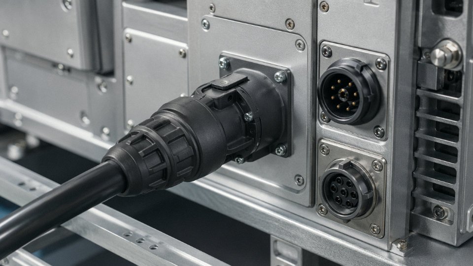
Match the connector series and part number to your IEC 60320 or industrial connector standard. Derate to 80% of rated current for any continuous load — a C19 connector rated at 16 A should not carry more than roughly 13 A continuously in practice. Specify IP rating based on installation environment: IP44 minimum for outdoor or wash-down areas, IP67 for submersed or high-pressure wash applications. If the assembly will be connected and disconnected frequently — test equipment, portable tools, event installations — specify expected insertion cycles and verify that the connector contact material (often silver-plated phosphor bronze) meets that service life. Interlocked connectors are non-negotiable in any application where disconnection under load is a live risk.
IEC 60320 connectors cover current ratings from 2.5 A to 16 A across the C1–C22 seriesTrue
The IEC 60320 standard defines appliance couplers including C1/C2 through C21/C22, with current ratings spanning 2.5 A, 6 A, 10 A, and 16 A depending on the coupler type, all within a 250 V AC maximum voltage rating for most series.
Supplier Qualification Criteria
ISO 9001 certification is a baseline, not a differentiator. What actually matters operationally: does the supplier hold third-party product certifications that match your destination markets (CE, CCC, UL, SAA, KEMA-KEUR), or are they offering self-declared compliance? Can they support a factory audit, either in person or via a third-party inspection agency? Check stated production capacity against your project volume — a supplier who can produce 50,000 meters per month on standard cable may have a six-week lead time on custom jacketed assemblies. Ask specifically for technical datasheets and CAD drawings before committing; a supplier who can’t provide dimensional drawings for a connector entry isn’t equipped to support engineering-level procurement.
Lead time on assembled cables — where the cable is terminated, tested, and shipped as a ready unit — is typically two to four weeks longer than bulk cable supply, depending on connector sourcing. Budget for that.
Jinda’s Supply Position for International Projects
Shandong Jinda Special Cable Group operates five production bases with a combined 470,000 m² of manufacturing space, which gives genuine flexibility on volume and simultaneous custom orders. The export team covers 50+ country markets and understands destination-specific certification requirements rather than treating CE as a universal pass. Standard and custom cable assemblies ship with CE, CCC, and ISO documentation as standard, samples dispatch within roughly seven days for qualification testing, and long-term supply agreement frameworks are available for recurring international project needs — useful for contractors running the same plant design across multiple countries over a multi-year timeline.