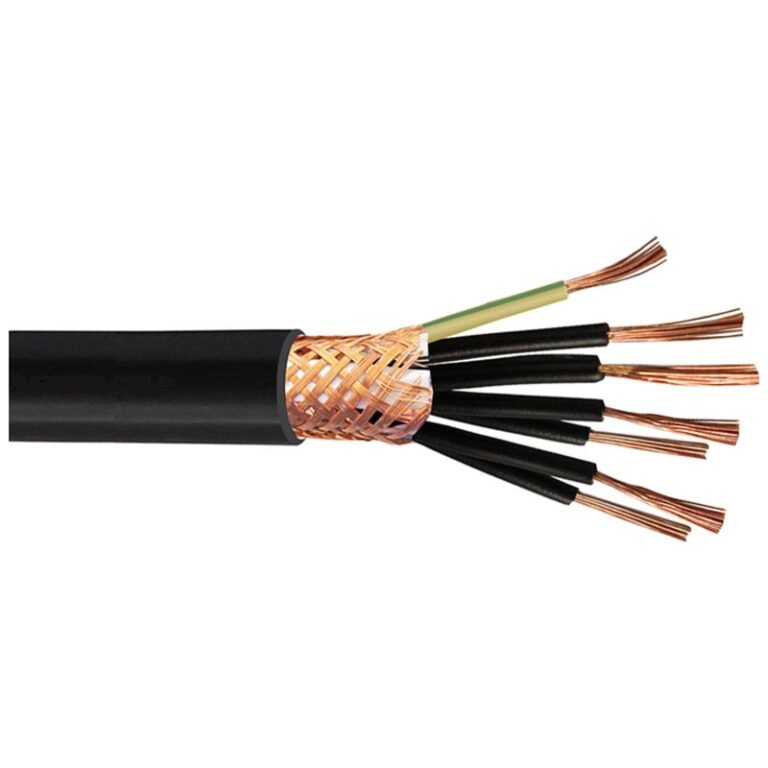
Picking the wrong cable flexibility class doesn’t announce itself until you’re already losing production. A Type 3 cable routed through a continuously moving cable carrier will work fine for weeks, sometimes months — then the conductors start work-hardening, micro-fractures develop at the strand level, and intermittent faults begin. By the time maintenance traces the fault to the cable rather than the drive or the PLC, you’ve burned through diagnostic labor, possibly scrapped a batch, and you’re looking at an unplanned shutdown to restring the carrier. That sequence is more common than most plant managers want to admit, and it almost always traces back to a specifying error made before the cable ever arrived on site.
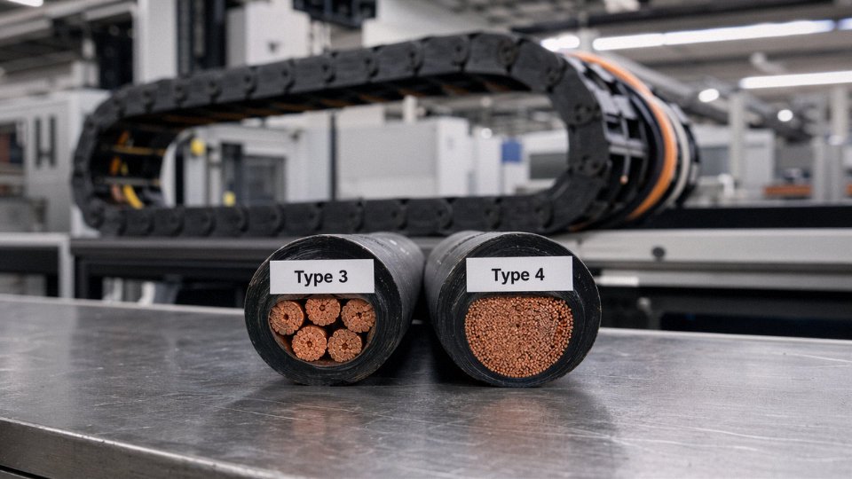
Type 3 cables use coarser stranding (IEC 60228 Class 2 or 3) and are designed for fixed or only occasional-flex installations. Type 4 cables use fine-strand Class 5 or 6 conductors — individual wire diameters typically below 0.21 mm — engineered for continuous-flex duty in cable trays, drag chains, and robotic arms, with flex-cycle ratings that can reach 10 million cycles depending on bend radius and jacket compound. The two types are not interchangeable in dynamic applications.
What makes this worth understanding in detail is that the physical difference between a Type 3 and Type 4 cable looks almost invisible on a reel — same outer diameter, same color coding, sometimes even the same voltage rating stamped on the jacket. The real gap is structural, buried in stranding geometry, jacket compound flexibility, and temperature range, and those differences have direct consequences for installation method, service life, and total cost of ownership. The sections below work through each of those dimensions practically.
Conductor Construction Decoded: Stranding Classes That Separate Type 3 from Type 4
IEC 60228 is the international standard that defines conductor classes, and if you work with flexible cables long enough, it becomes second nature. For everyone else, here’s how it maps to reality.
Class 1 is solid wire — single conductor, zero flex tolerance, used in building wiring you never touch after installation. Class 2 is concentric-stranded with relatively thick individual wires, again intended for fixed installation; your typical 7-wire or 19-wire power cable sits here. Class 3 adds slightly finer stranding for what the standard calls “flexible” use, though in practice that usually means occasional repositioning, not continuous movement. Classes 5 and 6 are where genuine flexibility begins — fine and ultra-fine wire bundles, respectively, engineered specifically for applications that involve real, repeated bending.
Type 3 cables map to Classes 2 and 3. Type 4 cables map to Classes 5 and 6. That one sentence explains most of what separates them, but the physical details matter enormously when you’re specifying cable for a moving application.
What a Type 3 Conductor Actually Looks Like Inside
Cut a 4 mm² Type 3 conductor and you’ll typically find 7 wires, each around 0.85 mm in diameter, laid in a single concentric bundle. Larger cross-sections step up to 19 wires, still with relatively coarse individual diameters — often 0.5 mm or above depending on the cross-section. The lay construction is concentric or bunched, optimized for dimensional consistency and ease of termination. These conductors strip cleanly, crimp predictably, and cost less per meter to produce than fine-wire alternatives.
None of that is a criticism. For fixed routing in a control panel or a conduit run that gets installed once and forgotten, Class 2 or 3 construction is entirely appropriate. The problem starts when someone routes that same cable over a cable carrier or through a robotic arm joint.
What a Type 4 Conductor Actually Looks Like Inside
A 4 mm² Type 4 conductor for a continuous-flex application might contain 196 individual wires, each below 0.21 mm in diameter. At larger cross-sections — say, 16 mm² or 25 mm² — you can be looking at 266 or more wires per conductor, sometimes arranged in a rope-lay construction where small bundles are twisted together before the entire assembly receives a final twist. Some manufacturers use a Litz-influenced geometry for high-cycle applications, though true Litz construction with individually insulated strands is more common in signal cables than power conductors.
The engineering logic is straightforward: when a conductor bends, the outer wires experience tension and the inner wires experience compression. With 7 thick wires, each wire carries the full stress of that cycle. With 196 fine wires, the bending stress is distributed across the entire bundle, and each individual wire deflects only a tiny fraction of what the thick-strand wire would. Work-hardening — the gradual embrittlement that leads to wire fracture — accumulates far more slowly.
This is also why copper purity matters more in Class 5 and 6 conductors. Fine-wire Type 4 conductors typically use electrolytic tough-pitch (ETP) copper with oxygen content tightly controlled, or tinned copper where the tin layer provides a modest buffer against surface oxidation that could accelerate fatigue cracking under repeated bending. Standard ETP copper in a Type 3 conductor is adequate because the wire simply isn’t flexing enough for work-hardening to become a failure mechanism.
| Characteristic | Type 3 | Type 4 |
|---|---|---|
| IEC 60228 Class | Class 2–3 | Class 5–6 |
| Typical wire count (4 mm²) | 7–19 wires | 196–266 wires |
| Individual wire diameter | 0.5 mm–0.9 mm (varies by cross-section) | Below 0.21 mm; down to 0.08 mm for Class 6 |
| Lay construction | Concentric or bunched | Rope-lay or fine-bunch, sometimes Litz-influenced |
| Minimum bending radius (installed) | 6–10× cable OD | 4–7.5× cable OD depending on jacket |
| Typical cross-section range | 0.5 mm²–240 mm² | 0.5 mm²–95 mm² (application-dependent) |
Why the Wire Drawing Process Upstream Matters
Producing wire at 0.08 mm consistently is not trivial. At that diameter, variations in the copper rod feedstock, drawing lubricant temperature, or die wear translate directly into tensile strength scatter across the spool — and if individual wire strength varies too widely within a bundle, the weaker wires fail first and the load redistributes onto their neighbors, accelerating the cascade.
Jinda’s conductor drawing and stranding lines are capable of producing wire down to 0.08 mm for Class 6 production, with process controls on lay pitch and wire count maintained batch to batch. That consistency matters for procurement: if you’re qualifying a cable for a 10-million-cycle flex application and the first production run passes qualification testing but subsequent batches drift in wire count or lay pitch, your field performance drifts with it.
Type 4 cables with Class 5 or 6 conductors per IEC 60228 can achieve flex cycle ratings up to 10 million cycles in continuous-flex tray and robotic applications, compared to Type 3 cables which are rated for static or occasional-flex installations only.True
IEC 60228 defines conductor flexibility classes, and cable manufacturers design Type 4 cables using Class 5–6 fine-wire conductors specifically for continuous-flex environments. The 10-million-cycle rating is a commonly specified benchmark for industrial cable carriers and robotic cable systems, dependent on bend radius, speed, and temperature conditions.
The wire count and diameter aren’t just catalog numbers — they’re the physical mechanism behind the performance gap between Type 3 and Type 4. Everything else downstream, the jacket compound, the lay pitch of the cores, the shield construction, sits on top of this foundation.
Insulation and Jacket Materials: How Type 3 and Type 4 Differ Beyond the Conductor
Most engineers, once they understand the stranding class difference, assume that’s the whole story. It isn’t. The conductor is where flexibility starts — the insulation and jacket are where it either survives long-term or slowly fails.
Why Compound Hardness Is the Hidden Variable
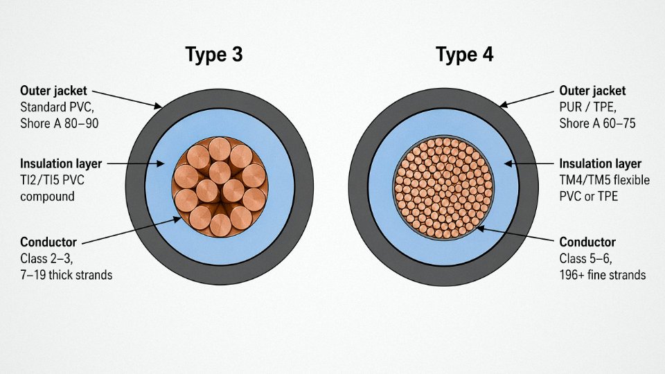
Type 3 cables typically use standard PVC insulation compounds — TI2 or TI5 per VDE 0281 — or XLPE where dielectric performance and cost efficiency are the priorities. These compounds sit at Shore A 80–90, which is hard enough that in a static installation, tray-routed and untouched for years, they perform exactly as intended. No issue there. But put that same insulation into a continuous-flex drag chain running 40 cycles per minute, and you’ll start seeing micro-cracks at the conductor interface within months. The insulation can’t deform and recover cleanly — it fatigues.
Type 4 cables use softer, more elastic compounds: flexible PVC grades like TM4 or TM5, TPE, TPU, or rubber (EPR/EPDM for demanding environments). Shore A hardness typically lands in the 60–75 range, depending on the specific formulation and operating temperature target. That 15–25 point difference on the durometer scale translates directly into the insulation’s ability to bend repeatedly without delaminating from the conductor surface beneath it. The softer compound flexes with the wire rather than against it.
Jacket Selection Follows the Same Logic — But Also Adds Protection
Type 3 cable jackets are usually standard PVC or LSZH, formulated for UV stability, oil resistance, or flame rating — all properties that matter in a fixed installation where the cable sits still and the environment does the work on it. These jackets are reasonably tough against occasional contact and chemical splash, but they’re not engineered for repetitive mechanical deformation.
Type 4 jackets are a different design target entirely. Highly plasticized PVC handles lighter continuous-flex duty reasonably well and stays cost-competitive. PUR (polyurethane) is the workhorse choice for serious applications — it resists abrasion at roughly 3–5 times the rate of standard PVC (actual values depend on the PUR grade and surface texture of the opposing surface), recovers its cross-section after being pinched or pulled, and holds up against cutting oils and coolant mist that destroy softer PVC over a season. TPE jackets offer a middle ground: better cold performance than PVC, cleaner processing than PUR, and decent chemical resistance. In cold-storage robotics running at -25°C to -35°C ambient, a standard Type 3 PVC jacket goes brittle enough to crack on a sharp tray edge; a TPE or PUR jacket at those temperatures remains pliable.
Temperature range is worth stating plainly. Standard Type 3 PVC-insulated cable: roughly -5°C to +70°C, which covers most benign indoor environments. Type 4 cables with PUR or TPE jacketing and appropriate insulation compounds: typically -40°C to +90°C, with XLPE or TPE-insulated versions reaching +105°C. Outdoor automation in northern climates, cold-chain conveyor systems, and foundry-adjacent installations all push those lower or upper limits in ways that eliminate Type 3 as an option.
Wall Thickness and Bending Stiffness
One detail that rarely shows up in catalog sheets: Type 4 cables often use slightly thinner insulation walls — still within IEC minimum tolerances — combined with the softer compound, specifically to reduce the cable assembly’s overall bending stiffness. Bending stiffness scales with wall thickness to the fourth power in a simplified beam model, so even a modest reduction in wall thickness meaningfully reduces the force required to flex the cable. Done incorrectly (too thin, wrong compound, poor extrusion control), this trades long-term dielectric integrity for short-term flexibility. Done right by a manufacturer with proper extrusion controls and compound qualification, it’s a legitimate design lever.
Type 4 flexible cables use softer insulation and jacket compounds with lower Shore A hardness than Type 3 cables, allowing repeated flex without cracking or delamination.True
This is consistent with IEC 60228 design intent and VDE 0281 compound classifications. Softer compounds (Shore A 60–75 vs. 80–90) deform elastically under bending rather than fatiguing at the conductor interface.
Materials Comparison: Type 3 vs. Type 4
| Layer | Property | Type 3 Typical | Type 4 Typical |
|---|---|---|---|
| Insulation | Compound type | PVC (TI2/TI5), XLPE | Flex PVC (TM4/TM5), TPE, EPR/EPDM |
| Insulation | Shore A hardness | 80–90 | 60–75 |
| Insulation | Temperature range | -5°C to +70°C | -40°C to +90/+105°C |
| Jacket | Compound type | Standard PVC, LSZH | Plasticized PVC, PUR, TPE |
| Jacket | Abrasion resistance | Moderate | High (PUR) to moderate (TPE) |
| Jacket | Flame rating | IEC 60332-1/-3 options | IEC 60332-1/-3 options (grade varies) |
| Jacket | Oil resistance | Moderate (PVC) to low | High (PUR), moderate (TPE) |
At Jinda’s compound development lab, PVC, LSZH, and TPU formulations go through cold-bend testing per IEC 60811-504, hot-set testing, and thermal aging cycles before any new compound is released to production. In practice, this matters most when a customer needs a Type 4 cable rated for both -40°C cold starts and sustained +85°C ambient near a press motor — standard catalog formulations often can’t satisfy both ends simultaneously without reformulation work.
Relevant Standards and Certification Landscape for Type 3 and Type 4 Cables
Standards compliance is where projects either move smoothly through customs and commissioning or stall for weeks waiting on re-testing. Getting the specification wrong at the procurement stage — ordering a cable that satisfies IEC 60228 Class 3 when the machine builder’s BOM calls for Class 5 or 6 — is the kind of mistake that surfaces at incoming inspection, not during quoting. By then, lead times have already been burned.
IEC 60228 as the Global Conductor Reference
IEC 60228 is the foundational document here. It classifies conductors by stranding fineness: Class 1 (solid), Class 2 (standard stranded), Class 3 (flexible stranded), Class 4 (flexible), Class 5 (fine-wire flexible), and Class 6 (ultra-fine, extra-flexible). Type 3 cables map to Classes 2 and 3 — adequate for fixed or occasionally disturbed installations. Type 4 cables require Class 5 or 6, where individual wire diameters typically run below 0.21 mm. That physical difference is what sustains flex-cycle life in the millions rather than the thousands.
For international procurement, referencing IEC 60228 class explicitly in your purchase order removes ambiguity. “Flexible cable” means different things to a supplier in Shanghai than to a machine designer in Stuttgart. “IEC 60228 Class 5, 4×2.5 mm²” does not.
IEC 60227 and IEC 60245 — Product-Level Standards
IEC 60227 covers PVC-insulated cables rated up to 450/750 V. The sub-parts most relevant here are 60227-4 (light and ordinary PVC sheathed flexible cords, applicable to Type 3 constructions) and 60227-5 (flexible flat cords, occasional flex). For genuinely continuous-flex Type 4 applications, IEC 60245 — rubber-insulated cables — becomes the more appropriate product standard, particularly 60245-4 and 60245-8, which address flexible trailing and welding cables with the mechanical durability requirements that PVC constructions often can’t meet alone without upgrading to TPE or XLPE jacket compounds.
VDE Certification for the European Market
In European industrial projects, the VDE mark on a Type 4 cable carries real weight. VDE 0281 applies to PVC-insulated flexible cables; VDE 0282 covers rubber-insulated types. The VDE mark is not self-declaration — it means a third party has independently verified conductor construction, insulation integrity, and, for flexible types, mechanical performance under repeated bending. When a procurement manager in Germany or the Netherlands specifies “VDE-certified flexible cable,” they are effectively locking in Class 5 or 6 conductor construction and verified jacket resilience. A cable without that mark, priced 8–15% lower, may fail qualification on the factory floor.
North American Requirements: UL 62, UL 508C, and NFPA 79
For shipments into the US and Canada, UL 62 governs flexible cords and cables in most general industrial applications. UL 508C covers wiring within power conversion equipment — variable frequency drives, servo systems — and implicitly demands flexible conductors where cables are routed around drive components inside enclosures. NFPA 79, the electrical standard for industrial machinery, references conductor flexibility classes directly when specifying wiring methods for moving machine parts. A Type 3 cable installed in a drag chain application on a machine destined for a North American customer will typically fail NFPA 79 review. That failure shows up during UL machine listing, not in your warehouse.
Application-Specific Standards That Effectively Mandate Type 4
Certain application standards don’t explicitly say “Type 4” but functionally require it. IEC 61439 (low-voltage switchgear and controlgear assemblies) specifies internal wiring flexibility requirements that push designers toward Class 5 or 6. IEC 61800-5-2, covering functional safety for drive systems, demands wiring integrity under continuous motion — a static-rated Type 3 cable is a liability in that context. PROFIBUS and PROFINET cable specifications, published by the respective industry organizations, explicitly require Class 5 or 6 conductors for bus cables deployed in drag chains or cable carriers. Using a Class 3 conductor there doesn’t just risk electrical performance; it risks triggering nuisance faults and fieldbus communication errors that maintenance teams spend days chasing before identifying the cable as the root cause.
RoHS 2 and REACH: Baseline Requirements for European Export
Both Type 3 and Type 4 cables exported into Europe must comply with RoHS 2 (Directive 2011/65/EU) and REACH (Regulation EC 1907/2006). For Type 4 cables specifically, PVC plasticizer selection matters. DEHP — historically common in flexible PVC compounds because it delivers good cold-temperature performance and flexibility — is on the REACH SVHC list and restricted under RoHS Annex II. Type 4 cables for European projects should use DINP, DIDP, or alternative non-phthalate plasticizer systems. Verify this with your supplier’s material safety data sheet and substance declaration, not just their product brochure.
Jinda holds IEC, CE, VDE, CCC, and ISO 9001 certifications, with per-shipment test reports available to customers.True
These certifications are maintained through ongoing third-party audits and testing programs, and per-shipment documentation is a standard feature of Jinda's export quality system, allowing customers to clear customs and satisfy project specification requirements without commissioning additional independent testing.
In practice, having a supplier who can produce these documents per shipment — not just on request once a year — compresses customs clearance and project qualification timelines noticeably. Procurement teams dealing with tight commissioning windows will recognize the difference.
Application Mapping: Where Type 3 Cables Belong and Where Type 4 Is Non-Negotiable
The technical distinctions in conductor stranding and jacket compounds only matter if you map them to the right installation context. Get that mapping wrong and you’re looking at premature conductor fatigue, unexpected downtime, or — going the other direction — paying 30–60% more per meter for flexibility you’ll never use.
The Type 3 Application Envelope
Type 3 belongs anywhere the cable goes in once and essentially stays put. Fixed conduit runs in industrial buildings, cable tray wiring between distribution panels, motor terminal box connections that won’t be re-routed during the machine’s service life, internal wiring inside a control panel where the occasional door swing is the only movement it ever sees. Utility distribution feeders. Branch circuit wiring in process plants.
The defining criterion isn’t whether the cable can bend — it’s whether it will be repeatedly bent during normal operation. A cable that gets bent once during installation, then clamped and forgotten, is a static installation even if it curves through a tight conduit elbow. Type 3 handles that comfortably and costs less doing it.
Over-specifying here is a real budget leak. On a large plant fit-out with several kilometers of internal panel and conduit wiring, substituting Type 4 across the board adds cost without adding service life in those static positions. Procurement managers sometimes push for Type 4 everywhere to simplify the BOM — understandable, but on high-volume projects the unit price difference accumulates fast.
The Type 4 Application Envelope
Type 4 is non-negotiable the moment the cable is part of a moving system. CNC machine tool drag chains (e-chains), robotic arm wiring on automotive assembly lines, automated welding positioners, gantry crane festoon systems, linear actuators in packaging machinery, servo drive cables on pick-and-place units — these are the environments that expose conductor fatigue. The cable isn’t just flexing occasionally; it may be cycling thousands of times per shift, millions of times per year.
A drag chain cable on a high-speed CNC that runs two shifts daily can accumulate 2–4 million flex cycles per year, depending on traverse speed and stroke length. Type 3 construction typically fails in these positions within weeks to a few months. The failure mode is usually a broken conductor strand that intermittently interrupts the signal or control circuit, and because it’s intermittent, it’s maddening to diagnose.
Industry-by-Industry Reference
| Industry | Representative Equipment | Recommended Type | Key Reason |
|---|---|---|---|
| Automotive manufacturing | Robotic welding arms, conveyor servo drives | Type 4 | Continuous high-cycle flex in drag chains and cable loops |
| Food and beverage processing | Packaging lines, rotary fillers, conveyors | Type 4 | Repeated motion; often washdown environments requiring flexible jacket compounds |
| Semiconductor fabs | Wafer handlers, precision linear stages | Type 4 | Low-particulate flex cables; tight bend radius in cleanroom gantries |
| Wind turbine nacelles | Pitch control cables, power cables inside nacelles | Type 4 | Continuous vibration plus torsional flex; IEC 61400-1 design environment implies Class 5/6 conductors |
| Port crane systems | Festoon systems, cable reels on overhead cranes | Type 4 | Continuous lateral bending and torsion under load cycles |
| Medical robotics | Surgical and rehabilitation robotic arms | Type 4 | High cycle count, compact bend radius, patient-safety reliability requirements |
| Data center cooling infrastructure | Fixed chilled water control wiring, static PDU feeds | Type 3 | Static installation post-commissioning; no operational movement |
| Building HVAC | Fixed conduit runs to AHUs, chiller control panels | Type 3 | Conduit is static after installation; flex during installation only |
Crane and Hoist: A Sector Worth Calling Out Separately
Festoon cable systems on overhead bridge cranes and harbor cranes are among the harshest cable applications that exist — continuous lateral bending, occasional torsion, and sometimes exposure to salt air or chemical splash. Type 4 construction is the baseline here, not a premium option. Cable reels add a torsional component that standard drag-chain Type 4 cables aren’t always optimized for; festoon-specific variants with reinforced jackets and carefully balanced stranding are worth specifying rather than defaulting to any Class 5/6 product.
Jinda produces festoon cables for port equipment exported to Middle East and Southeast Asian terminalsTrue
Jinda's product range includes festoon cables for port and harbor crane applications, and the company ships to customers across the Middle East and Southeast Asia as part of its export operations to 50+ countries.
Wind Energy: Vibration and Torsion Combined
Inside a wind turbine nacelle, the cable environment is genuinely unforgiving. The structure vibrates continuously at frequencies tied to rotor speed — typically in the 0.3–1.5 Hz range depending on turbine class — and the nacelle yaws to track wind direction, imposing a slow torsional flex on cables that run from the nacelle down the tower. IEC 61400-1 doesn’t prescribe conductor class directly, but the design loads it defines effectively require Class 5 or Class 6 construction to survive the 20-year design life without conductor fatigue failures. Using Type 3 here isn’t just a performance risk; it’s a maintenance cost problem, because nacelle cable replacement means crane mobilization.
The HVAC Borderline Case
Building automation and HVAC is where engineers most often over-specify. A flexible conduit drop to a fan-coil unit looks like a flex application because the conduit itself is corrugated and hangs loosely. But if the conduit is fixed at both ends and the cable inside it doesn’t move after the mechanical contractor finishes, it’s a static installation. Type 3 is correct. The conduit provides mechanical protection and a small amount of vibration isolation; the cable just carries the signal. Specifying Type 4 here doesn’t cause harm, but it adds cost that serves no function.
The honest rule: ask whether the cable itself moves relative to its termination points during normal system operation. If the answer is no, Type 3 is the right and economical choice.
A Simple Decision Path
Before finalizing a specification, run through this sequence mentally: Will the cable move during normal operation? If no — Type 3. If yes, how frequently? Occasional re-routing during maintenance only — Type 3 is likely sufficient. Regular, repeated cycling in service — move to Type 4. From there, consider bend radius relative to cable diameter (tighter than 7.5× OD in continuous flex means you need a verified festoon or drag-chain variant, not just any Class 6 product), and then factor in temperature range and chemical exposure to pin down the jacket compound. That path eliminates most misspecification errors before they reach the procurement stage.
Electrical Performance Parameters: Voltage Rating, Current Capacity, and Signal Integrity Compared
One of the more persistent misconceptions in cable procurement is that Type 4 is purely a low-voltage signal or control cable. It isn’t. Both Type 3 and Type 4 cables are manufactured across the same voltage tiers — 300/300 V, 300/500 V, 450/750 V, and up to 0.6/1 kV for power versions — and the voltage rating is governed by insulation wall thickness and compound selection, not by how many wires make up the conductor. Confusing stranding class with voltage class causes real specification errors, usually discovered during factory acceptance testing or, worse, at customs when the submitted data sheet doesn’t match the declared rating.
Type 4 cables are available in 0.6/1 kV power ratings, not only in low-voltage control or signal configurations.True
Voltage rating is determined by insulation thickness and dielectric properties per IEC 60502 and related standards, not by conductor stranding class. Fine-stranded Class 5/6 conductors used in Type 4 cables are routinely insulated and sheathed to achieve 0.6/1 kV ratings for power flex applications.
Current Capacity and the Resistance Trade-Off
For the same nominal cross-section — say, 2.5 mm² — a Type 4 cable carries the same rated current as a Type 3 cable per IEC 60364-5-52 ampacity tables. The conductor area is the conductor area. What does change is DC resistance. IEC 60228 permits a slightly higher maximum DC resistance for Class 5 and Class 6 conductors compared to Class 2 solid or Class 3 stranded, because the sheer number of wire-to-wire contact points adds a small but measurable contact resistance. In practice this works out to roughly 2–5% higher DC resistance, depending on wire diameter, lay length, and whether the conductor is tinned or bare copper. Over a short cable run — 10 to 15 meters — this is essentially irrelevant. Across a 200-meter production line with twenty flex tracks, it accumulates. At that scale, recalculate your voltage drop budget before finalizing cross-section.
VFD Output Cables and the Skin Effect Argument
At 50 or 60 Hz, there is no meaningful skin effect difference between Type 3 and Type 4. Full stop. But VFD output cables are a different situation. Modern drives switch at PWM frequencies anywhere from 2 kHz up to 16 kHz, and at those frequencies current tends to crowd toward the conductor surface. The finer individual wire diameters in Class 5/6 conductors — typically below 0.21 mm per wire — are closer to or below the skin depth at those frequencies, which means each wire carries current more uniformly. The result is reduced AC resistance, lower harmonic losses, and slightly cooler operation under sustained VFD duty. This is not a theoretical advantage; it shows up in thermal imaging on long VFD runs where the flex cable consistently runs a few degrees cooler than an equivalent solid-conductor alternative.
Capacitance, Inductance, and Signal Integrity in Shielded Versions
For servo drive cables and fieldbus lines running PROFINET or EtherCAT, the geometry consistency of Type 4 stranding matters more than most engineers expect. Symmetric, tightly controlled lay lengths in Class 5/6 conductors produce more uniform capacitance per unit length and more stable characteristic impedance along the cable’s travel path. In a flex track that bends 30,000 times a day, a cable that subtly changes geometry with each cycle will introduce signal reflections that accumulate into communication faults. It usually shows up as intermittent drive faults or bus timeouts — the kind of fault that’s genuinely maddening to diagnose because it disappears when you swap the cable and doesn’t reappear immediately.
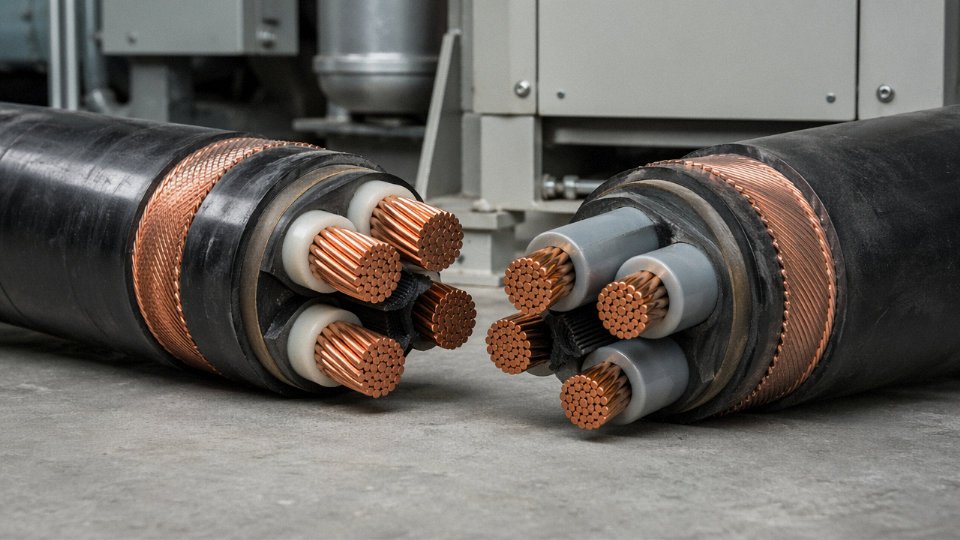
Shield construction amplifies this. Type 3 shielded cables typically use foil plus a drain wire, or at most a single-braid shield. Adequate for static runs. Type 4 flex cables use braided copper shields with optical coverage above 85%, almost always tinned copper, specifically to resist fretting corrosion — the micro-abrasion that occurs when shield wires rub against each other through millions of flex cycles. Bare copper braid in continuous-flex service oxidizes and eventually develops high-resistance patches that compromise EMC performance just when the machine is at peak production.
| Parameter | Type 3 | Type 4 |
|---|---|---|
| Nominal voltage range | 300/300 V – 0.6/1 kV | 300/300 V – 0.6/1 kV |
| DC resistance increase vs. Class 2 (IEC 60228) | ~0–2% above Class 2 solid baseline | ~2–5% above Class 2 solid baseline |
| Minimum insulation resistance (typical, 1 min at 500 V DC) | ≥100 MΩ·km | ≥100 MΩ·km |
| Capacitance per unit length (shielded, 1 mm² typical) | 120–180 pF/m (depends on insulation wall and compound) | 110–170 pF/m (tighter geometry gives more consistent value) |
| Shield coverage (shielded versions) | 65–80% optical coverage, foil or single braid | >85% optical coverage, tinned copper braid |
| Recommended max VFD cable run (before common-mode choke needed) | 50–100 m depending on drive manufacturer | 80–150 m, varies with shielding quality and cable capacitance |
The capacitance values in that table depend heavily on insulation compound and wall thickness, not just conductor class — so treat them as orientation ranges rather than design absolutes. When you’re specifying a shielded servo cable for a machine with a 20-meter reach, ask the cable supplier for the actual measured capacitance per meter on their specific product. Datasheet estimates and measured production values can diverge by 15–20% depending on how tightly the manufacturer controls insulation wall concentricity.
Total Cost of Ownership Analysis: Initial Price vs. Replacement and Downtime Costs
The upfront price difference between Type 3 and Type 4 cable is real and visible on any purchase order. Type 4 fine-wire cable typically runs 15–40% more per meter than a dimensionally equivalent Type 3 cable at the ex-works level, depending on conductor cross-section, jacket compound, and order volume. That premium exists for tangible reasons: drawing copper wire to sub-0.21 mm diameters requires more die passes, tighter process control, and higher scrap rates than producing Class 2 or Class 3 strands. Premium TPE or XLPE jacket compounds cost more than standard PVC. The stranding itself takes additional machine time. None of that is padding — it’s real manufacturing cost.
What procurement managers sometimes do is stop the analysis there. That’s the mistake.
The Single-Incident Math Is Already Damning
Consider a fairly ordinary scenario: a CNC machining center running a 25-meter drag chain, originally wired with Type 3 cable because the BOM listed “flexible cable” without specifying stranding class. At a cross-section of 1.5 mm², the incremental cost difference between Type 3 and Type 4 at that length is somewhere in the range of $80–$150, depending on the supplier and the jacket spec. Uncomfortable but not alarming.
Eighteen months in, conductor fatigue fracture starts — intermittent at first, which is actually worse than a clean failure because the machine throws fault codes, operators reset and run, and diagnostics time accumulates before anyone opens the cable carrier. When the cable finally fails hard, unplanned downtime in a typical automotive Tier 1 machining environment costs roughly $2,000–$8,000 per hour, depending on whether that cell is a bottleneck, what shift premiums apply, and whether the OEM line downstream gets starved. Cable swap including accessing the drag chain, pulling the old cable, re-routing and re-terminating takes 4–6 hours in most plants — longer if a maintenance crew wasn’t keeping the chain accessible or if the machine model requires partial disassembly to get at the routing path. Total incident cost: $12,000–$50,000. Against an $80–$150 specification decision made eighteen months earlier.
A single unplanned downtime event from cable failure in an automotive Tier 1 plant typically costs more than the entire cable procurement budget for that machine.True
No explanation available.
Scale It Across a Facility and the Numbers Get Uncomfortable
A plant with 40 CNC cells, each running Type 3 cable in flex positions, experiencing roughly one fatigue failure per cell over an 18-month cycle — that’s 40 incidents across a 3-year period. Even at conservative downtime figures, the aggregate cost runs well into six figures. The entire cable procurement budget for the facility at initial fit-out likely doesn’t approach that number. In practice, failure rates cluster: cells running similar duty cycles tend to fail within the same maintenance window, which means multiple incidents in a short period rather than a tidy one-per-month spread.
Standardization Reduces a Different Kind of Risk
There’s a less-discussed cost that doesn’t show up in downtime reports. When a plant stocks both Type 3 and Type 4 cable in similar sizes, technicians doing emergency repairs under pressure grab what’s available. In my experience, stockroom labeling during a 2 a.m. breakdown does not get close scrutiny. Standardizing on Type 4 for all flex positions eliminates that failure mode entirely — one cable type, one inventory line, no substitution errors.
Warranty and Liability Exposure
Using Type 3 cable in a position the machine builder specified for continuous-flex service can void the equipment warranty outright — most major servo and robotics OEMs are explicit about conductor class requirements in their installation manuals. In European markets, if a cable failure in a non-compliant installation contributes to a safety event, liability exposure under Machinery Directive 2006/42/EC becomes a serious issue. That’s not a hypothetical; it’s the kind of thing that surfaces during incident investigations when insurers start asking why the installed cable didn’t match the specification.
Where Bulk Procurement Changes the Economics
The 15–40% per-meter premium narrows considerably at volume. Jinda’s long-term supply agreements for Type 4 continuous-flex cables typically deliver 8–15% cost reduction versus spot procurement pricing, depending on annual volume, drum length standardization (100 m, 200 m, 500 m drums, or custom cut-to-length), and contract duration. For a plant running 40+ CNC cells or a machine builder sourcing cable across a full product line, that reduction — combined with price-lock provisions that hedge against copper market volatility — often closes most of the gap with Type 3 spot pricing while buying the full lifecycle performance. The math isn’t complicated. The hard part is making it visible to decision-makers before the first failure, not after.
Installation, Handling, and Maintenance Best Practices Specific to Each Cable Type
Getting the specification right is only half the job. A correctly specified Type 4 cable installed with torsional twist or routed through an overloaded drag chain will fail almost as fast as the wrong cable entirely — and the failure mode looks identical, which means the root cause often gets misattributed.
Bending Radius: Static Rules for Type 3, Dynamic Rules for Type 4
Type 3 cables in fixed installations should be bent to no less than 6–8× the cable’s outer diameter during laying. That range depends on jacket material and conductor cross-section — a stiff, large-diameter PVC-jacketed Type 3 cable sits toward the 8× end; a smaller, softer version can tolerate 6×. These are one-time bending events during installation, not repeated flex cycles, so the conductor isn’t accumulating fatigue. The cable just needs to hold its routed shape without the insulation cracking at the bend point over years of thermal cycling.
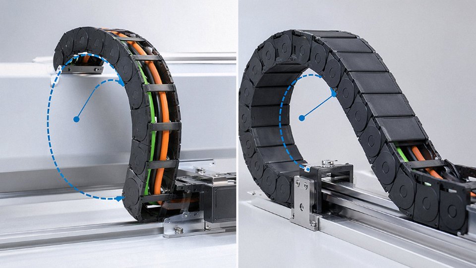
Type 4 drag-chain cables operate under an entirely different mechanical regime. The dynamic bending radius — the radius the cable actually traces as the chain travels — must stay at 7.5–10× OD minimum, and that number comes jointly from the cable manufacturer’s datasheet and the e-chain supplier’s specification. Both need to agree. Going below this threshold doesn’t cause gradual degradation; conductor fatigue accumulates exponentially once you’re under the rated radius, and a cable specified for 10 million flex cycles might deliver 500,000 cycles or fewer if the chain geometry is even marginally tight. Always verify the actual travel radius of the installed chain, not just the chain’s catalog bend radius — those numbers are not always the same once brackets and offsets are accounted for.
Torsion Is the Hidden Failure Mode
Torsional stress is underappreciated in the field, and it ruins a lot of otherwise correctly specified Type 4 installations. When a cable is unwound from a drum by rotating the drum on its axis rather than unrolling it flat, every meter pulled introduces a fraction of a twist. Run 30 meters through a drag chain that way and the cable has a continuous spiral rotation along its length. In dynamic flex, that twist adds a third stress axis to bending compression and tension — the conductor strands are now working in three directions simultaneously, and flex life drops severely.
The correct method: mount the drum so it rolls and pays off from the outside. Lay the cable flat into the e-chain channels without any rotational preload. If you pull the cable from a fixed coil on the floor, uncoil it in the direction of travel, don’t lift loops off the top.
Termination: Ferrules Are Not Optional on Type 4
Fine-wire Class 5 and 6 conductors in Type 4 cables will splay under a screw terminal if you skip ferrules. Individual wires may fold under the clamp, miss the contact surface entirely, or break off over vibration cycles. The result is increased contact resistance, localized heating, and eventually a thermal event at the terminal block. Specify ferrules per DIN 46228 — the correct size matched to the conductor cross-section — and use a ratchet crimping tool, not pliers. This matters more for Type 4 than Type 3, but honestly, fitting ferrules on Type 3 conductors costs almost nothing and removes a failure path worth eliminating.
Fine-wire Type 4 conductors terminated without ferrules at screw connections show significantly higher contact resistance under vibration and thermal cycling compared to ferrule-terminated connections.True
IEC 60999-1 and practical terminal block testing both confirm that unsupported fine-wire bundles lose contact area under clamping torque and mechanical vibration, increasing resistance and creating hotspot risk.
Fill Factor and Inter-Cable Abrasion in Drag Chains
E-chain manufacturers publish fill factor guidelines for a reason. The general industry figure is roughly 60% of the chain’s internal cross-sectional area — though some suppliers allow up to 65% depending on chain geometry and cable jacket hardness. Pack the chain tighter than that and cables can’t move freely through the bend; they press against each other and against the chain walls. For Type 4 cables with softer TPU or flexible PVC jackets, that friction abrades the jacket at the entry and exit points — exactly where the cable is already under the most stress. In practice, this shows up as jacket wear through to the insulation within a year or two on high-cycle systems. Count your cables, calculate the bundle cross-section, and leave margin.
Maintenance Inspection Intervals
Type 3 fixed cables don’t need much attention in normal environments — a visual inspection every 2–5 years is usually adequate, checking for jacket cracking (especially on cables near heat sources or exposed to UV), discoloration at terminals, and any signs of corrosion at connection points. In aggressive chemical environments, tighten that to annually.
Type 4 flex cables in continuous-cycle applications need inspection every 3–6 months, specifically at the chain entry and exit zones. That’s where jacket wear concentrates. Look for surface cracking, flattening, or any visible abrasion through to the insulation layer. A cable showing jacket wear at those points is telling you something is mechanically wrong — check the bend radius, the fill factor, and whether any torsion has been introduced since installation.
Storage and Handling Before Installation
Fine-wire Type 4 cables kink more easily than Type 3 during handling. If someone coils a reel of Type 4 cable onto a small-diameter spool or leaves it in a tight coil on a cold warehouse floor overnight, the conductor geometry can be permanently distorted before the cable ever sees the machine. Minimum storage coil diameter should be at least 20× cable OD — for a 10 mm cable, that’s a 200 mm minimum coil diameter. Jinda’s shipping drums are sized with appropriate core diameters specifically to prevent this during transit, but once the drum arrives and someone starts pulling cable on site, that protection ends.
For OEM and EPC customers working through drag-chain layout, bend radius verification, or e-chain compatibility questions, Jinda’s technical support team provides pre-sales engineering consultation as a standard part of the procurement process — not an add-on.
Frequently Asked Questions About Type 3 and Type 4 Cables
Can I use Type 4 cable in a fixed installation where Type 3 is specified?
Yes, without reservation. Type 4 meets or exceeds every electrical and mechanical requirement that Type 3 satisfies, so substituting up is always safe from an engineering standpoint. The real question is economic: Type 4 typically costs 20–45% more per meter depending on conductor cross-section and jacket material, so routinely specifying it for static conduit runs or junction-box drops is money left on the table. If a project already has Type 4 on hand from a flex-application order and needs to finish a fixed run, use it. Just don’t make it standard practice in your BOM without a cost review.
What happens if I install Type 3 cable in a drag chain?
This is probably the most expensive mistake a maintenance engineer can make without realizing it immediately. Type 3 conductors — Class 2 solid or Class 3 stranded — are simply not built for the repeated bending stress a drag chain imposes. The larger individual wire diameters concentrate bending strain, initiating fatigue micro-cracks at the outer wires first. Depending on cycle rate and bend radius, you’ll typically see the first intermittent open-circuit faults within a few weeks to a few months. Left in service, those micro-cracks propagate, insulation cracks follow, and you’re looking at arc fault risk inside the chain — not just a nuisance shutdown, but a potential fire event or damaged servo drive. Never use Type 3 in any continuous-flex application. The cost difference between the two cable types is trivial compared to one unplanned line stop.
Is “Type 4 cable” the same as “Class 5 cable” or “Class 6 cable”?
Not exactly, and this trips up procurement teams regularly. Class 5 and Class 6 are conductor stranding classifications defined in IEC 60228 — they specify maximum individual wire diameter and minimum wire count for a given cross-section. Type 4 is a product-level designation (common in IEC and German VDE traditions, think H05VV5-F or ÖLFLEX-style nomenclature) that requires Class 5 or 6 conductors but also specifies insulation and jacket compound, wall thicknesses, and overall construction. A cable can have a Class 5 conductor and still fail as a Type 4 product if the jacket compound is too rigid for dynamic service. The conductor class is necessary but not sufficient.
Type 4 cables always use Class 5 or Class 6 conductors per IEC 60228True
The fine stranding required for Type 4 flex performance is defined by IEC 60228 Class 5 (flexible) and Class 6 (extra-flexible), with individual wire diameters typically below 0.21 mm for common cross-sections. This is a verifiable construction requirement, not marketing language.
Do Type 4 cables require special connectors or terminals?
Yes — and skipping this step quietly ruins many otherwise correct installations. Fine-wire conductors in Class 5 or 6 construction will splay and lose strands if inserted bare into screw-cage or spring-cage terminals. Always crimp an end-sleeve ferrule per DIN 46228 Part 1 (plain ferrules) or Part 4 (insulated ferrules) before termination. The ferrule consolidates the wire bundle, maintains consistent contact area, and prevents individual strands from backing out under vibration. Contact resistance creep from improperly terminated fine-wire conductors is a slow failure — it usually shows up as unexplained signal errors or thermal hotspots at the terminal block months after commissioning, by which point the root cause is hard to trace.
What is the maximum flex cycle life of a properly specified Type 4 cable in a drag chain?
Premium Type 4 drag-chain cables from reputable manufacturers test to roughly 3 million to 10 million flex cycles at the rated dynamic bending radius. Where you land in that range depends on several real variables: actual bend radius relative to the rated minimum (tighter bend = dramatically shorter life), cycle frequency, ambient temperature, and whether the cable is exposed to cutting oils or other chemicals that attack the jacket. Jinda provides flex-cycle test certificates for its continuous-flex product range, which matters when you’re qualifying a cable for a high-speed pick-and-place line running 60+ cycles per minute.
Are Type 3 and Type 4 cables available in multi-core configurations?
Both types are manufactured in multi-core builds, commonly from 2 cores up to 50-plus cores. In practice, Type 4 multi-core control cables show up constantly in CNC control cabinets, servo amplifier wiring, and sensor/actuator network runs where the bundle travels through a drag chain or festoon system. Screening options — overall foil, braided, or combined — are available on both types, though screened Type 4 multi-cores for encoder and fieldbus signals are the more demanding construction.
How do I verify that a supplier’s Type 4 cable is genuinely Class 5 or 6 and not mislabeled?
Request the IEC 60228 conductor class test report showing measured DC resistance per unit length for the specific cross-section. Class 5 and 6 resistance limits are tighter than Class 2 or 3 because finer, more numerous wires produce lower resistance per cross-section. If the measured value is within the Class 5 or 6 column of IEC 60228 Table 2, the conductor is legitimate. Also ask for wire count and individual wire diameter data from the production batch — a supplier who can’t provide those figures from their own QC records is a supplier worth treating cautiously.
Does Jinda offer custom colors, numbering, and drum lengths for Type 4 cable orders?
Yes. Jinda supports custom core colors, sequential number printing on each core, custom jacket colors for customer or system identification, and drum lengths ranging from 50 m up to 2,000 m. Minimum order quantities run as low as 500 m total for standard constructions, and sample quantities are available for qualification testing before a full procurement commitment. For project-specific requirements — non-standard cross-sections, unusual core counts, or specific chemical-resistance jacket compounds — the engineering team works from technical drawings rather than just catalog specs.
How to Write a Bulletproof Cable Specification for Type 3 or Type 4 Procurement
A specification that says “flexible control cable, 4-core, 1.5 mm²” is not a specification — it’s an invitation for a supplier to ship whatever sits in the warehouse. Procurement engineers who have been through a substitution dispute know exactly how this ends: the wrong product arrives, project commissioning is delayed, and the contract language offers no recourse because nothing was locked down clearly enough. Getting the spec right takes maybe thirty extra minutes upfront and saves weeks on the back end.
The Six Elements That Make a Cable Spec Binding
Every cable specification, whether it goes into a purchase order, a project BOM, or a vendor RFQ, needs six specific elements. Miss any one of them and you’ve left a gap a supplier can legally — and often will — exploit.
1. IEC or UL product standard reference. This pins the cable to a defined test and construction regime. “IEC 60227 Part 5” or “UL 62” means something enforceable. “Meets international standards” means nothing.
2. Conductor cross-section in mm² or AWG. State one system and stick to it throughout the document. Mixing mm² in the spec and AWG in the drawing creates conversion errors that compound at the cable tray fill calculation stage.
3. Number of cores. Including earth core designation where applicable — “4G1.5” (four conductors plus integrated green-yellow earth) versus “4×1.5” (four conductors, no integrated earth) are different products.
4. IEC 60228 conductor class — not just the word “flexible”. This is where most specs fall apart. “Flexible” is commercially undefined. Class 5 means maximum individual wire diameter of 0.21 mm for most cross-sections; Class 6 is finer still, for ultra-flex robotic applications. Class 2 is solid or conventional stranded, acceptable for fixed installation but not for any dynamic run. Writing the class number removes any ambiguity.
5. Insulation and jacket compound with sub-standard. PVC insulation TI2 per IEC 60227, Shore A hardness max 75 for flexible grades, or TPE/XLPE for high-heat environments — specify the compound family and hardness where flex life matters. A Type 4 drag-chain cable jacketed in a hard-durometer PVC will crack within months regardless of conductor class.
6. Voltage rating. 300/500 V and 450/750 V are not interchangeable; insulation wall thickness differs, and so does spacing in panel wiring.
Model Specification Lines You Can Copy
For a Type 3 fixed-installation cable: 4-core, 2.5 mm², IEC 60227 Part 5 (H05VV-F equivalent), Class 2 stranded conductor, PVC insulation TI2, PVC outer sheath TM1, 300/500 V, flame-retardant per IEC 60332-1-2, RoHS 2 compliant.
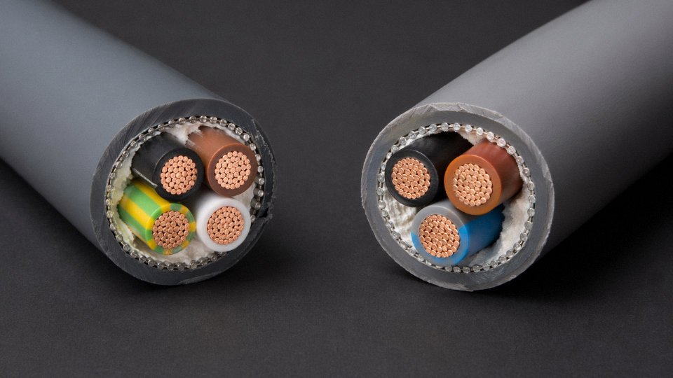
For a Type 4 drag-chain or continuous-flex cable: 4-core, 1.5 mm², IEC 60228 Class 5 fine-wire stranded conductor, flexible PVC insulation Shore A max 75, highly flexible PVC jacket Shore A max 70, 300/500 V, dynamic bending radius ≥7.5× OD, minimum 3 million flex cycles at rated radius, tested per UL 62 or VDE 0281, RoHS 2 and REACH SVHC compliant.
Those two lines are structurally different in ways that matter legally and technically. The drag-chain spec includes a flex-cycle floor and a bending radius limit — without those, a supplier has no obligation to test dynamic performance at all.
Standard Designator Shorthand
The IEC designator system — H07RN-F for rubber-jacketed flexible, NSGAFÖU for heavy mining flex, ÖLFLEX-equivalent designators for industrial control — gives you a single alphanumeric string that encodes conductor class, insulation material, voltage, and application category simultaneously. Use it. Jinda’s product catalog cross-references every major standard designator directly to product codes, which cuts quoting turnaround considerably because the technical team isn’t hunting through ambiguous descriptions.
Why Vague Language Is a Contractual Liability
Phrases like “multi-strand cable,” “flexible cable,” or plain “control cable” without conductor class and flex-cycle rating create a substitution window. A supplier can ship a Class 3 stranded product against a “flexible cable” line item with no contractual breach. In practice, if that cable goes into a drag chain on a stamping press running two shifts, it will fail within six to eighteen months — but by then the supplier’s liability is arguable at best.
Using vague flex cable language in purchase orders without specifying IEC 60228 conductor class creates no contractual protection against Class 3 product substitution for Class 5 applications.True
IEC 60228 conductor class is the only standardized, auditable metric that distinguishes Type 3 and Type 4 conductor construction. Without it, 'flexible' and 'multi-strand' carry no defined technical meaning in international trade or dispute resolution.
Qualification Samples Before Bulk Commitment
Before releasing a volume order — particularly for a new application or a new supplier relationship — request a 10–20 meter qualification sample. Run three checks: IEC 60228 conductor resistance measurement (a quick verification that wire count and diameter match the class claim), cold-bend test per IEC 60811-504 at the cable’s rated minimum temperature (this catches brittle compound formulations that look fine at room temperature), and a physical inspection of drum packaging and reel labeling against spec. Jinda provides free qualification samples for projects above a threshold volume, and the technical team can advise on test protocols if your lab needs reference procedures.
Reach out to Jinda’s technical sales team directly for specification review, custom cable design support — including non-standard cross-sections, halogen-free variants, or armored flex configurations — and volume pricing structured for long-term supply partnerships. Getting the specification right before the first order ships is the whole game.