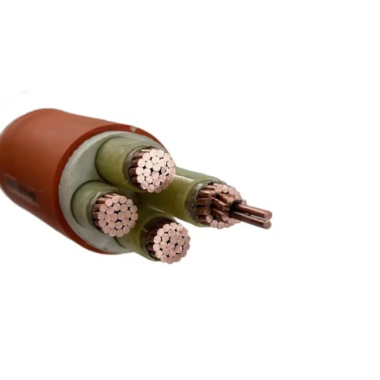
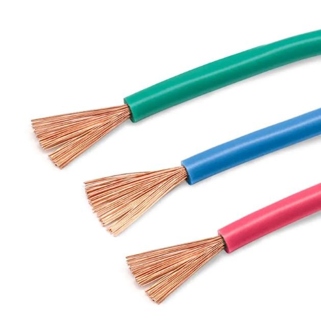
Pick the wrong conductor flexibility class and you will find out at the worst possible moment — a drag chain that starts shedding copper strands at month four, a robotic weld cell that throws nuisance faults every Tuesday morning until someone finally pulls the cable and sees the fractured core. Replacing a festooned cable run mid-production costs far more than the price difference between conductor classes ever would have; in a high-cycle automation line, unplanned downtime from conductor fatigue can run to several thousand dollars per hour depending on line rate and product value. The fix is not complicated, but it requires understanding what actually separates a Type 4 conductor from a Type 5 before the purchase order goes out.
Type 5 cables are not universally better than Type 4 — they are better in high-flex, high-cycle applications. Type 5 conductors use far finer individual wires (roughly 196 to over 1,500 per conductor depending on cross-section) to distribute bending stress across more strands, which dramatically extends fatigue life in drag chains, robotic arms, and continuous-flex installations. Type 4 is adequate and often preferable for fixed or occasional-flex duty where the finer geometry adds cost without benefit.
What makes this comparison genuinely interesting is that the conductor strand geometry also changes the physical cable dimensions — a 16 mm² Type 5 conductor runs measurably wider than its Type 4 equivalent — which flows downstream into conduit fill calculations, connector termination choices, and even how reliably the cable seats in a compression lug under vibration. There is more engineering here than most procurement specs acknowledge.
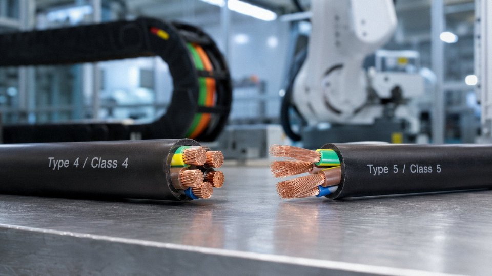
IEC 60228 Conductor Classification Decoded: How Type 4 and Type 5 Are Actually Defined
IEC 60228 is the international standard that defines minimum wire counts, maximum DC resistance, and geometric construction requirements for copper conductors in finished cables. It doesn’t tell you what the cable is for — that’s the job of application standards like IEC 60245 or IEC 60227 — but it does set the floor on conductor construction quality. If you’re reading a supplier’s data sheet and it says “Class 5 flexible conductor,” this is the document that gives that claim a precise, verifiable meaning.
Class 4 — Stranded Flexible, the Middle Ground
Class 4 is a stranded flexible conductor, sitting between the rigid Classes 1 and 2 (solid and concentric-stranded) and the fine-wire constructions of Classes 5 and 6. The wire count requirements are modest: at 1.5 mm² the standard requires a minimum of 7 wires, at 10 mm² it steps up to 19 wires, and at 50 mm² you’re looking at a minimum of 19 wires as well, though many manufacturers exceed these figures. Individual wire diameters in Class 4 typically fall in the 0.4–0.8 mm range depending on cross-section, which is why a Class 4 conductor feels noticeably stiffer than Class 5 when you’re routing it through a tight bend radius.
Maximum DC resistance at 20°C for Class 4 copper mirrors Class 2 in most cross-sections — the standard doesn’t reward you with lower resistance for the finer stranding, and in a few cross-sections Class 4 actually carries a marginally higher resistance limit than Class 2. That’s a point worth checking on data sheets: higher flexibility does not automatically mean lower resistance.
Class 5 — Fine-Wire Stranded, the Workhorse for Moving Applications
Class 5 is where the real engineering difference lives. The wire count jumps dramatically: a 1.5 mm² Class 5 conductor typically contains around 196 individual wires, versus just 7 for Class 4 at the same cross-section. At 16 mm², you’re commonly looking at 126 wires or more, each wire in the 0.15–0.25 mm diameter range. That fine geometry is what gives Class 5 its bend radius advantage and fatigue resistance — the individual wires redistribute mechanical stress across a far larger number of strands, which is why Class 5 conductors can handle 30,000+ flex cycles in drag-chain or robotic tow applications without a measurable DC resistance increase beyond 2%.
The bundle twist pitch also tightens in Class 5 construction. Shorter lay lengths help maintain conductor roundness during repeated flexing and reduce the tendency of the bundle to “bird-cage” — that’s where wires splay outward at a termination point after heavy cycling, a failure mode that shows up quietly in crimped connections before it causes an obvious fault.
Class 6 — Ultra-Fine Wire, a Different Problem Set
Class 6 uses even finer wires than Class 5, often below 0.15 mm in diameter, and is designed for extremely tight bend radii and continuous high-cycle flexing — think handheld power tools or coiled cords. It matters here only because some suppliers list “Class 5/6” on data sheets as a combined category, which is sloppy and can mislead procurement. Class 6 conductors typically have higher DC resistance than Class 5 at the same cross-section, and they demand more careful termination practice. Don’t specify Class 6 when Class 5 is sufficient; you’ll pay more and get a conductor that’s harder to crimp reliably in the field.
The Wire Count and Resistance Table You Should Keep at Your Desk
| Conductor Class | Min. Wires at 1.5 mm² | Min. Wires at 2.5 mm² | Min. Wires at 6 mm² | Min. Wires at 16 mm² | Min. Wires at 50 mm² | Max DC Resistance at 20°C, 16 mm² (Ω/km) | Typical Wire Diameter Range |
|---|---|---|---|---|---|---|---|
| Class 4 | 7 | 7 | 16 | 16 | 19 | ≤ 1.15 | 0.40–0.80 mm |
| Class 5 | 196+ | 196+ | 196+ | 126+ | 196+ | ≤ 1.15 | 0.15–0.25 mm |
| Class 6 | Higher than Class 5 | Higher than Class 5 | Higher than Class 5 | Higher than Class 5 | Higher than Class 5 | ≤ 1.20 (varies) | < 0.15 mm |
Resistance values depend on conductor purity grade and actual cross-sectional area achieved; verify against the specific standard revision your project requires.
Class 5 conductors meet the same maximum DC resistance limits as Class 4 at most cross-sections under IEC 60228True
IEC 60228 sets equal or near-equal maximum DC resistance values for Class 4 and Class 5 at most common cross-sections. The flexibility gain in Class 5 comes from finer wire geometry, not from relaxed resistance limits — both classes must meet comparable conductivity performance.
National Standards and Where the Terminology Gets Messy
VDE 0295 (Germany) maps directly onto IEC 60228 classes — Classes 1 through 6 correspond one-to-one, so a VDE 0295 Class 5 specification and an IEC 60228 Class 5 specification are effectively asking for the same thing. BS 6360 (United Kingdom) uses similar class designations, though the historical versions diverged slightly on wire count minimums at smaller cross-sections; always confirm which edition is referenced. UL is where things get genuinely confusing in cross-border procurement. UL doesn’t use the Class 4/5/6 language at all — it categorizes conductors by strand count and wire gauge under its own AWG-based system, and a UL-listed “flexible” conductor may or may not meet IEC 60228 Class 5 minimums depending on the specific AWG size and construction. If you’re sourcing cable for a project that requires both UL listing and IEC 60228 Class 5 compliance, ask your supplier for explicit test data against both standards. Assuming equivalence without verification is one of the more common and expensive mistakes in export projects.
Physical Construction Differences: Wire Geometry, Packing Density, and Insulation Compatibility
The difference between a Type 4 and Type 5 conductor isn’t just a wire count on a data sheet — it’s a fundamentally different approach to how copper is assembled, and if you’ve ever cut open both cables side by side, the contrast is immediately obvious. Type 4 individual wire diameters typically run 0.20–0.51 mm depending on cross-section, with larger conductors using the coarser end of that range. Type 5 drops those individual wires down to roughly 0.10–0.21 mm. That sounds like a minor metallurgical detail. It isn’t.
Wire Diameter and What It Actually Means for Surface Area
Finer wires mean more of them — a lot more. A 16 mm² Type 4 conductor might bundle around 50–70 individual wires depending on the manufacturer’s lay geometry; a Type 5 at the same cross-section will typically carry 196 or more. All that extra surface area comes with a trade-off: copper oxidizes at its surface, and a Type 5 conductor has dramatically more exposed copper surface per metre of cable than a Type 4 equivalent. In dry indoor environments this rarely matters. In marine installations, humid switchrooms, or chemical plants where chlorinated vapors are present, oxide buildup on fine-wire conductors can creep into terminations and raise contact resistance over time — sometimes enough to cause heat at crimp joints after a few years of service. This is exactly why tinning decisions (more on that shortly) matter more for Type 5 than for Type 4.
Stranding Geometry and the Outer Diameter Penalty
Type 4 conductors are almost always concentrically stranded — wires laid in defined, nested layers around a centre core, which packs reasonably efficiently and produces a predictable circular cross-section. Type 5 conductors more commonly use bunched or rope-lay stranding, where groups of fine wires are twisted together in sub-bundles before being assembled into the full conductor. This gives the superior flexibility, but the packing factor is slightly worse. Voids between sub-bundles are real, and they add up.
At 16 mm², a Type 4 conductor comes in around 4.7 mm diameter; Type 5 lands closer to 5.1 mm. That’s an 8–12% diameter increase, which sounds trivial until you’re trying to retrofit Type 5 cable through conduit that was sized for Type 4 — conduit fill calculations change, and if you’re already at 40% fill on a crowded tray, that difference matters. Check your conduit fill before specifying upward.
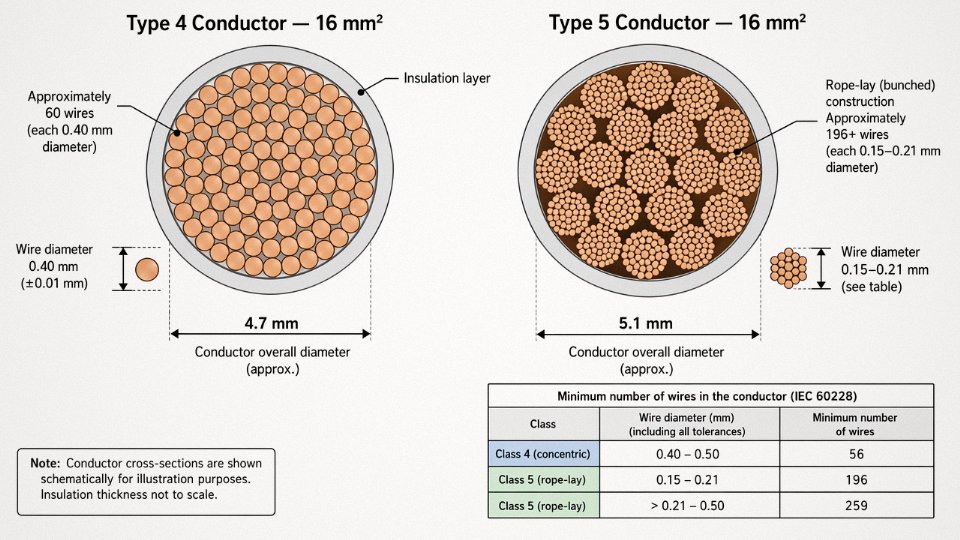
Alt text: Labeled cross-section diagram comparing a 16 mm² Type 4 conductor (left) and a 16 mm² Type 5 conductor (right). Type 4 shows concentric stranding with approximately 50–70 individual wires at 0.20–0.51 mm diameter and an overall conductor diameter of approximately 4.7 mm. Type 5 shows bunched/rope-lay stranding with 196+ individual wires at 0.10–0.21 mm diameter, overall conductor diameter approximately 5.1 mm. Both diagrams label the insulation layer thickness and conductor boundary.
Insulation Compatibility Over Fine-Wire Bundles
Finer wire bundles create a different interface for insulation compounds. The interstices — small voids between wire surfaces — are more numerous and smaller in a Type 5 bundle, and not all insulation materials fill them the same way. Standard PVC (the default for most general-wiring cable) has adequate adhesion on Type 4 but can leave micro-voids in Type 5 conductors, which becomes relevant in applications where moisture ingress or partial discharge under high voltage stress is a concern.
XLPE performs better in this regard because the crosslinking process allows it to flow before curing, improving void-filling. EPR is arguably the most forgiving over fine-wire bundles — its elastic nature maintains contact with the conductor surface even when the bundle geometry shifts during flexing, which is why it shows up frequently in trailing cable and mining cable specs. Silicone rubber is used in high-temperature applications above 150°C but requires careful extrusion control over Type 5 conductors because its low viscosity can produce inconsistent wall thickness. In practice, any reputable manufacturer running silicone over Type 5 should be able to show you wall thickness measurements from production QC, not just a nominal value.
Tinning: When It’s Specified and What It Changes
Tinning a Type 5 conductor reduces its flexibility compared to bare copper at equivalent construction.False
Tin plating on individual fine wires adds negligible mass and does not meaningfully alter the mechanical flexibility of the conductor bundle. Flexibility is determined by wire diameter and stranding geometry, not by a thin surface tin coating. The IEC 60228 Class 5 minimum flex performance requirements apply equally to tinned and bare copper conductors.
Tinned copper is specified for Type 5 conductors in marine environments, food-processing plants with regular wash-downs, and chemical installations where sulfur or halogen vapors are present. The tin layer — typically 1–3 µm — acts as a barrier against oxidation at the wire surface and also makes the conductor significantly easier to solder, which matters for certain termination methods. It does add a small increment to conductor resistance (tin conductivity is roughly 15% lower than copper), so for conductors above 50 mm² where resistance budget is tight, it’s worth confirming the manufacturer’s resistance figures are within IEC 60228 limits for the tinned version specifically. Usually they are, but check the actual test report rather than assuming.
Bare copper Type 5 is fine for the vast majority of dry industrial applications and costs less. Specifying tinned across a whole project when only a portion of the installation genuinely needs it is a common procurement inefficiency — the premium runs roughly 5–12% on conductor cost depending on copper prices and wire diameter, and for large cable quantities that adds up.
Flexibility Performance Under Real Operating Conditions: Flex Life, Bend Radius, and Dynamic Load Data
The flex-life gap between Type 4 and Type 5 is where the specification decision gets real. On a data sheet, the difference looks like a conductor class number. On a production floor where a drag chain cycles 300 times a day, it shows up as unplanned downtime, premature cable replacement, and — at worst — a nuisance fault that takes a maintenance team half a shift to trace.
How Flex Life Is Actually Measured
Flex life testing typically follows IEC 60227-2 test methods adapted for drag-chain and robotic-arm rigs: the cable is clamped at one end, routed through a simulated drag-chain track or around a defined mandrel, and cycled through a prescribed travel stroke at a set speed. Failure is declared when conductor resistance increases by more than 2% above baseline, when individual wire breakage becomes audible or detectable under magnification, or when cross-section loss — measured by cutting and examining the conductor — exceeds allowable limits. That 2% resistance threshold matters because it corresponds roughly to the point where heat generation in the conductor starts climbing noticeably, and in tight conduit bundles that becomes a thermal management problem, not just a mechanical one.
The stroke length, mandrel diameter, and travel speed all affect the cycle count at failure. So when a supplier quotes “50,000 cycles,” the honest question is: at what bend radius, what travel speed, and what cable OD? Flex-life numbers without those parameters are marketing, not specifications.
Benchmark Data: Where Type 4 and Type 5 Diverge
Type 4 conductors — typically 7 to 19 wires per conductor depending on cross-section — are rated for roughly 5,000 to 15,000 flex cycles in standard drag-chain applications. That range depends heavily on the insulation material and how well the jacket controls conductor bundle movement; a good PVC jacket on a Type 4 cable will outperform a poorly designed TPE jacket on the same conductor class. Still, even the better end of the Type 4 range is a hard ceiling in high-cycle environments.
Type 5 fine-wire conductors — 196 wires or more at 1.5 mm², scaling upward with cross-section — are typically rated from 50,000 to 500,000+ flex cycles under the same drag-chain test conditions. That is not a subtle improvement. It is a 10x to 30x difference, and it is almost entirely attributable to the finer wire geometry distributing bending stress across a larger number of individual wires, each of which sees far less strain per cycle.
Type 5 conductors can achieve 10x to 30x more flex cycles than Type 4 conductors in drag-chain applicationsTrue
Fine-wire stranding in IEC 60228 Class 5 conductors distributes bending stress across significantly more individual wires, reducing per-wire strain per cycle and dramatically extending fatigue life versus Class 4 concentric or bunched constructions.
Minimum Bend Radius: The Numbers That Drive Equipment Layout
For static installations, Type 4 typically requires a minimum bend radius of 4× cable OD; Type 5 is similar, usually 3–4× OD. The real difference appears in dynamic applications. Type 4 dynamic bend radius guidance sits at 8–10× OD. Type 5, with a well-designed core geometry and appropriate jacket, commonly achieves 6–8× OD dynamically. That might sound marginal, but at a 25 mm OD cable, the difference between a 250 mm and a 175 mm bend radius affects whether a cable chain fits in the machine frame at all. Machine designers working with tight drag-chain envelopes regularly run into this, usually after the frame has already been fabricated.
Jacket stiffness compounds the issue. A hard PVC outer jacket on a Type 5 conductor can effectively negate the conductor’s flexibility advantage by introducing jacket-level bending resistance. Silicone, TPU, or special low-temperature PVC compounds restore that advantage, which is why the cable’s complete construction — not the conductor class alone — determines the achieved bend radius in practice.
Torsional Flexibility for Robotic Applications
Drag-chain flex is one stress mode. Robotic cables face a different one: torsion. A six-axis robot wrist can impose ±180° to ±360° of torsion per meter of cable length with each work cycle. Under repeated torsional stress, Type 4 concentric-stranded conductors tend to develop wire breakage at the outer layers first, because the geometric arrangement locks individual wires into fixed helical paths that cannot redistribute torsional strain. Type 5 bunched stranding, where wires are not geometrically constrained to concentric layers, handles torsional cycling significantly better. For robotic applications rated above roughly 2 million robot cycles over cable service life, Type 5 with purpose-designed torsional core geometry is not optional — it is the floor specification.
Choosing the Right Type for the Application Cycle Rate
For fixed installations and cables that flex only occasionally — think panel wiring that gets repositioned during maintenance, or machine interconnects that move during setup but not during production — Type 4 is entirely adequate. Even at 500 flex cycles per year, a 10,000-cycle-rated Type 4 cable has a theoretical service life of 20 years, which exceeds most equipment design lives.
The calculus changes fast once continuous motion enters the picture. A drag chain cycling 200 times per day accumulates 73,000 cycles per year. At that rate, a Type 4 cable at 10,000-cycle rating fails in under two months. A Type 5 cable rated at 500,000 cycles under the same conditions has a theoretical service life of nearly seven years — roughly the window between major machine overhauls in most manufacturing environments. That comparison is what makes Type 5 the minimum viable specification for CNC axis cables, elevator trailing cables, and any drag chain running production shifts.
Electrical Performance Comparison: Resistance, Current Capacity, Voltage Drop, and High-Frequency Behavior
One of the most common misunderstandings I hear from procurement engineers is the assumption that switching from Type 4 to Type 5 somehow “costs” something electrically — that all those extra fine wires must introduce more resistance, or that the cable will run hotter, or that you’ll need to upsize the cross-section to compensate. None of that is true for standard power-frequency applications, and it’s worth being precise about why.
DC Resistance: The Standards Are Aligned, Not Divergent
IEC 60228 specifies the same maximum DC resistance at 20°C for Class 4 and Class 5 conductors across virtually all cross-sections. At 1.5 mm², both classes must meet ≤12.1 mΩ/m. At 16 mm², both sit at the same ceiling. The finer individual wire diameter in a Type 5 conductor changes the geometry of how the copper is packed, but the total copper cross-sectional area — and therefore the bulk resistivity — is what the standard is actually controlling. A well-drawn Class 5 conductor from a reputable mill will hit essentially the same measured resistance as a Class 4 conductor of the same nominal cross-section.
Type 5 (Class 5) conductors have higher DC resistance than Type 4 (Class 4) conductors of the same cross-section.False
IEC 60228 specifies identical maximum DC resistance limits for Class 4 and Class 5 conductors at equivalent cross-sections. The flexibility upgrade does not degrade the resistance specification; both classes must meet the same maximum Ω/km values at 20°C.
Current-Carrying Capacity: Governed by Cross-Section, Not Conductor Class
IEC 60364-5-52 ampacity tables are built around thermal behavior: the cross-sectional area of copper, the insulation material, the installation method, and ambient temperature. Conductor class doesn’t appear as a variable. A 4 mm² Type 5 cable installed in free air under the same thermal conditions as a 4 mm² Type 4 cable will carry the same rated current — roughly 32–38 A depending on insulation type and installation method, give or take for derating factors. If you’re specifying a flexible cable for a machine tool and bumping up from Type 4 to Type 5, you do not need to upsize the conductor. Doing so wastes copper and adds weight and cost unnecessarily.
Voltage Drop: Same Cross-Section, Same Result
Since voltage drop in a DC or 50/60 Hz AC circuit is a direct function of conductor resistance per unit length, and since that resistance is essentially identical between Class 4 and Class 5 for a given cross-section, your voltage drop calculations don’t change when you switch cable classes. This sounds obvious once stated, but I’ve seen procurement specs where an engineer upsized from 2.5 mm² Type 4 to 4 mm² Type 5 “to be safe.” That’s a real cost increase for no electrical benefit.
Where Type 5 Actually Earns an Electrical Advantage: High-Frequency Circuits
This is the one area where the fine-wire construction of Type 5 genuinely changes the electrical picture, and it matters more than most people realize in modern factory environments. Above roughly 10 kHz — the range you’re operating in with variable frequency drives, servo amplifiers, and some switching power supply outputs — the skin effect starts pushing current toward the outer surface of each individual wire rather than distributing it evenly through the cross-section. The skin depth in copper at 10 kHz is approximately 0.66 mm, dropping to around 0.21 mm at 100 kHz.
In a Type 4 conductor, individual wire diameters at 16 mm² might run 0.4–0.9 mm. In a Type 5 conductor at the same cross-section, individual wires are typically 0.1–0.3 mm — meaningfully below the skin depth at higher frequencies. The result is that a Type 5 conductor maintains lower effective AC resistance at VFD carrier frequencies compared to a Type 4 conductor of identical nominal cross-section. The effect is modest in most industrial drives operating at 4–16 kHz carrier frequency, but in high-cycle servo applications or where cable runs exceed 20–30 m, the reduced AC resistance contributes to lower harmonic losses and slightly cooler operation over time.
Resistance and Ampacity Reference Table
| Cross-section (mm²) | Max DC resistance, Class 4 (Ω/km at 20°C) | Max DC resistance, Class 5 (Ω/km at 20°C) | Typical current rating, free air (A)* |
|---|---|---|---|
| 1.5 | 12.1 | 12.1 | 17–22 |
| 2.5 | 7.41 | 7.41 | 23–30 |
| 4 | 4.61 | 4.61 | 31–40 |
| 6 | 3.08 | 3.08 | 40–51 |
| 10 | 1.83 | 1.83 | 54–70 |
| 16 | 1.15 | 1.15 | 73–94 |
| 25 | 0.727 | 0.727 | 95–121 |
| 35 | 0.524 | 0.524 | 117–150 |
| 50 | 0.387 | 0.387 | 141–182 |
*Current rating range reflects variation by insulation class (PVC vs. XLPE/EPR) and installation method per IEC 60364-5-52. Conductor class is not a variable in these calculations.
The practical takeaway: for DC and standard power-frequency circuits, specifying Type 5 over Type 4 is a flexibility and mechanical decision, not an electrical one. You’re not trading anything away electrically, and you’re not gaining anything in a 50 Hz power circuit either. Where the electrical argument for Type 5 does hold up independently is in high-frequency servo and drive cabling, and that’s worth noting explicitly in your cable specification when those applications are in scope.
Application-Specific Fit: Where Type 4 Is the Right Choice and Where Type 5 Is Non-Negotiable
The mistake I see most often isn’t under-specifying — it’s over-specifying. A procurement manager reads about Type 5’s superior flex life, decides it’s “safer,” and specifies it across the board. The result is 15–25% unnecessary cable cost on a building wiring package where the conductors will never flex more than twice in their service life. The opposite error is worse, though. Someone cuts cost by substituting Type 4 into a drag-chain application, and within six to eighteen months the fine wire bundles have work-hardened, resistance has crept up, and the machine trips on overcurrent. Replacing cable inside a live production cell costs far more than the original price difference.
Where Type 4 Earns Its Place
Fixed electrical installations are the natural home of Type 4. Building wiring pulled into conduit per IEC 60227, motor winding lead connections that get repositioned maybe twice a year during scheduled maintenance, transformer secondary busbars with occasional service bends — these are all low-cycle applications. The conductors flex during installation and then essentially stay put. The finer wire geometry of Type 5 offers nothing here except a slightly larger outer diameter (roughly 8–12% more at 16 mm², as noted earlier) that actually works against you in tight conduit fills.
Switchboard internal wiring is another clear Type 4 territory. The cables route once, get dressed neatly, and stay there. Similarly, general-purpose flexible cords in light-duty consumer or commercial equipment — desk lamps, portable tools used occasionally, extension leads in office environments — don’t accumulate enough cycles to stress a Type 4 conductor meaningfully. In all these cases, capturing the cost advantage of Type 4 is sound engineering, not a compromise.
Where Type 5 Is Non-Negotiable
Robotic welding cells are the canonical example. A six-axis welding robot running two shifts can put 10,000–20,000 flex cycles per day on the power and signal cables routed through its cable management system. Type 4 will typically show measurable resistance increase well before the 30,000-cycle threshold that IEC 60228 Class 5 conductors are qualified to; in a high-cycle robot that’s weeks, not years. CNC servo drive cables, crane pendant cables (which combine flexing with torsion), elevator trailing cables, and AGV power leads all fall into the same category — the application geometry imposes continuous, repetitive mechanical stress and fatigue failure is a real outcome, not a theoretical one.
Wind turbine nacelle cabling deserves a specific mention because the environment compounds the problem. The nacelle yaws continuously, cables twist with it, and temperature swings between -20 °C and 60 °C or more accelerate jacket embrittlement. Stage and entertainment rigging cables get coiled, uncoiled, dragged across concrete, and sometimes run over by equipment — Type 5 with an abrasion-resistant jacket is the baseline, not an upgrade.
The Drag-Chain Sub-Category
Even specifying Type 5 isn’t always enough for drag-chain applications. A standard IEC 60228 Class 5 conductor gives you the wire count, but a drag-chain cable in a machine tool environment also needs a controlled stranding pitch to prevent wire migration under repeated flexing, an oil-resistant PUR outer jacket (a plain PVC jacket will crack within months in coolant mist), and usually a copper braided shield to handle the EMI environment of variable-frequency drives. Jinda’s drag-chain specific products address all three of these on top of the base Class 5 conductor — the conductor class is the foundation, not the whole specification.
Offshore and Marine Applications
IEC 60092 marine cables for flexible trailing leads on offshore platforms and in vessel engine rooms standardly specify tinned Type 5 copper conductors. Tinning matters here because the combination of sustained vibration, salt-laden humidity, and elevated temperatures accelerates oxidation at individual wire surfaces inside the conductor bundle. Bare copper works fine in most industrial environments; in a ship engine room or a subsea umbilical termination, it’s a maintenance liability.
Type 5 conductors are always the better choice regardless of application typeFalse
Type 5 is only the correct choice where repeated mechanical flexing, dynamic load cycles, or environmental severity justify the higher cost and larger conductor diameter. In fixed installations, conduit wiring, and low-cycle applications, Type 4 delivers equivalent electrical performance at lower cost and better conduit fill geometry.
Decision Matrix
| Application Type | Typical Flex Cycles/Day | Environment Severity | Recommended Conductor Class | Primary Standard |
|---|---|---|---|---|
| Building conduit wiring | < 5 | Dry/indoor | Type 4 (Class 4) | IEC 60227 |
| Switchboard internal wiring | < 5 | Dry/indoor | Type 4 (Class 4) | IEC 60364 |
| Motor lead connections (fixed) | < 10 | Moderate | Type 4 (Class 4) | IEC 60227 |
| General portable cords (light duty) | 20–100 | Moderate | Type 4 or Type 5 | IEC 60227 |
| CNC servo / machine tool cables | 5,000–15,000 | Coolant / EMI | Type 5 + PUR jacket | IEC 60228, IEC 60204 |
| Robotic welding cell cables | 10,000–20,000 | High / EMI | Type 5 + shielded drag-chain | IEC 60228 |
| Elevator trailing cables | 3,000–8,000 | Moderate–high | Type 5 | IEC 60228, EN 50214 |
| Crane pendant / festoon cables | 1,000–5,000 | Outdoor / wet | Type 5 + UV/oil resistant | IEC 60228 |
| AGV power leads | 2,000–6,000 | Industrial floor | Type 5 + PUR | IEC 60228 |
| Wind turbine nacelle cables | 500–2,000 (torsion) | High / thermal | Type 5 + torsion-rated jacket | IEC 60228, IEC 61400 |
| Marine/offshore trailing leads | Variable | Salt / vibration | Type 5 tinned copper | IEC 60092 |
Cycle counts are estimates — actual values depend on robot speed, chain travel length, bend radius, and ambient temperature. Use these as triage, then verify against your specific machine duty cycle before finalizing the spec.
Cost Analysis and Total Cost of Ownership: When Paying More for Type 5 Saves Money Over the Project Lifecycle
The price tag on a reel of cable is the wrong number to optimize. Procurement managers who buy on unit price alone consistently make the wrong call on flexible conductor specification — and the cost shows up six to eighteen months later as unplanned downtime, not as a line item anyone can trace back to the original cable decision.
What Drives the Price Premium
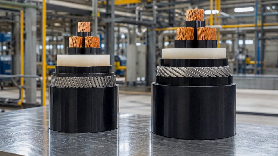
Type 5 conductors are more expensive to manufacture, and the reasons are straightforward once you understand the process. Drawing copper wire down to the fine gauges required for high-strand-count construction means more die passes, more intermediate annealing steps, slower line speeds, and a higher scrap rate compared to the coarser wire used in Type 4. Depending on the cross-section, the strand count difference is substantial — a 16 mm² Type 5 conductor might carry several hundred individual wires where a Type 4 equivalent carries far fewer, each wire finer and more labor-intensive to produce consistently.
In practice, this adds roughly 8–18% to conductor manufacturing cost at equivalent copper prices, depending on cross-section size, target strand count, and how tightly the manufacturer controls die wear and drawing speed. That doesn’t translate directly to finished cable pricing in a one-to-one way — insulation, jacketing, and overhead dilute the conductor cost — so the finished cable price premium typically lands in the 5–15% range. What it depends on: insulation system complexity, cable diameter, order volume, and whether the supplier is running the fine-wire drawing in-house or buying pre-drawn wire on the spot market.
The Downtime Math That Changes the Conversation
Run a simple scenario: a robotic welding line producing 500 units per hour, with a margin of around $200 per unit. A Type 4 cable in a continuous-flex drag chain fails at roughly 12–18 months. The failure causes 4 hours of unplanned downtime — realistic for fault diagnosis, parts sourcing if the cable isn't stocked, and rethread through a packed cable carrier. Cable replacement cost: around $1,200 including labor.
Lost production: 500 units × 4 hours × $200 margin = $400,000. Add the replacement cost and you’re looking at roughly $401,200 for a single failure event.
A Type 5 equivalent cable in the same application might cost $1,380 at the time of purchase — $180 more. With flex life 30 to 50 times longer under IEC 60228-compliant testing conditions, a well-specified Type 5 cable in that drag chain should comfortably outlast the point where a Type 4 would have failed. The ROI calculation doesn’t require a spreadsheet. The $180 premium pays for itself against the very first avoided failure, with the next several years of avoided failures representing pure margin recovery.
Type 5 cables in continuous-flex drag-chain applications typically outlast Type 4 by a factor of 30–50x in flex cycle life under IEC 60228 test conditions.True
IEC 60228 Class 5 conductors are designed for repeated flexing applications, and testing protocols in drag-chain and robotic cable qualification routinely demonstrate this lifecycle differential versus Class 4 when tested under equivalent bend radius and cycle rate conditions.
Maintenance Intervals Tell the Same Story
Facilities running Type 5 in drag-chain applications — assembly robots, automated guided vehicles, overhead festoon systems — commonly report cable replacement intervals of 3 to 7 years. The same installation with Type 4 often needs attention every 6 to 18 months, depending on cycle rate, bend radius, and whether the cable carrier was sized correctly in the first place. Over a ten-year facility lifespan, that’s potentially five or more replacement cycles avoided per cable run, each one carrying labor, material, and — often underestimated — production schedule disruption costs.
The Case Against Over-Specifying
Here’s the part procurement managers sometimes miss: Type 5 is not always the right answer, and specifying it everywhere is its own form of budget waste.
Fixed conduit runs. Terminal box interconnects. Junction panel wiring that gets touched once during commissioning and then never moves. In these static or near-static applications, Type 4 performs identically on every electrical parameter that matters and costs less. The fine-wire construction of Type 5 buys you nothing in a conduit that never flexes — it just adds cost and, marginally, can complicate conduit fill calculations because the Type 5 conductor at 16 mm² runs around 5.1 mm in diameter versus approximately 4.7 mm for Type 4, adding roughly 8–12% to conduit fill area at that cross-section.
The cost-conscious approach is zone-based specification: identify which cable runs see continuous flex, which see occasional repositioning, and which never move. Right-specify each zone rather than defaulting to Type 5 across the board.
Volume Procurement and Single-Supplier Consolidation
Where this gets practically useful for large projects is supplier consolidation. Running a mix of Type 4 and Type 5 across a facility used to mean managing two separate supply chains, two lead times, and two quality systems — which many procurement managers quietly solved by over-specifying Type 5 everywhere just to simplify purchasing. That’s understandable, but it’s expensive.
With manufacturing capacity across five production bases and over 470,000 m² of production space, Jinda produces both classifications at volume, to consistent quality standards, under one roof. That means a single project can carry mixed specification — Type 4 for static runs, Type 5 for dynamic applications — without splitting procurement across multiple vendors or accepting batch-to-batch variation in insulation chemistry or conductor geometry. For large industrial projects with dozens of cable types, that consolidation advantage is real and worth factoring into total cost of ownership alongside the per-meter price.
Quality Verification and Acceptance Testing: How to Confirm You Are Receiving Genuine Type 5 Conductor
The cable industry has a counterfeiting problem. It is not subtle. Conductors labeled “Class 5 flexible” routinely arrive with wire counts that match Class 2, cross-sections that are 10–15% light, and test certificates that reference labs whose accreditation expired years ago. For a procurement manager buying 50,000 meters of flexible cable for a new automated line, the consequences of accepting a mislabeled reel are real: premature conductor fatigue, nuisance trips on resistance-sensitive drives, and replacement costs that dwarf whatever savings looked attractive on the original quote.
Here is how to catch it before the cable goes into conduit.
Wire Count Verification
The most direct physical check is also the simplest in concept, though it takes patience. Take a clean cross-section cut — a sharp blade, one stroke, no sawing — and fan the wires out under a magnifier or lay the face against a flatbed scanner for digital image analysis. IEC 60228 Table 2 specifies minimum wire counts per cross-section for Class 5. At 1.5 mm², the minimum is 30 wires; at 16 mm², it is 84. Genuine high-quality Class 5 construction typically runs well above those minimums — 196 wires at 1.5 mm² is not unusual from a reputable manufacturer. If your count lands anywhere near the Class 2 minimums (7 wires at 1.5 mm², for example), someone is lying on the data sheet.
Digital image analysis tools have gotten good enough that a phone camera and basic edge-detection software can count wires in a 16 mm² conductor in under a minute. There is no excuse not to run this check on incoming reels from any new supplier.
DC Resistance Testing
This is your fastest quantitative pass/fail check, and you can do it on the receiving dock. Measure a 1-meter sample with a Kelvin bridge or a quality micro-ohmmeter — a two-wire measurement on a short sample will give you garbage from contact resistance. Record conductor temperature at the time of test. IEC 60228 Section 4 gives the correction formula to normalize to 20°C; do not skip this, especially in summer when ambient dock temperatures can push 35°C and throw off your calculation by 5–6%.
The Class 5 resistance limit at 1.5 mm² is 13.3 mΩ/m maximum at 20°C. If you are measuring 14.5 mΩ/m, the conductor is either undersized, using a lower-conductivity alloy, or is not Class 5 at all. Full stop.
Cross-Section Verification by Weight
Weigh a 1-meter conductor sample (stripped of insulation) to the nearest 0.01 g. Divide by 8.89 g/cm³ for bare copper or 8.85 g/cm³ for tinned. This gives you actual cross-section in mm². A nominal 16 mm² conductor should come back at 15.8–16.2 mm². Anything below 15.5 mm² on a Class 5 declaration is a non-conformance worth escalating.
IEC 60228 permits a negative tolerance on actual conductor cross-section as long as the DC resistance limit is met.True
IEC 60228 sets resistance limits, not dimensional limits, as the compliance criterion. A conductor can be physically slightly undersized if the resistance stays within the class maximum — but in practice, undersized conductors from low-quality suppliers usually fail both checks simultaneously.
Certificate and Mark Verification
A legitimate IEC 60228 Class 5 test report from an accredited third-party lab will carry a ILAC-MRA signatory mark, name a specific test date, list the exact cross-section and construction tested, and be traceable to a sample lot — not just a product family. VDE and KEMA certificates are respected in European markets; CCC is required for China domestic supply; CE marking on cable typically indicates self-declaration against harmonized standards rather than third-party certification, so it carries less weight in isolation.
Ask your supplier to provide factory test records alongside the third-party certificate. The resistance values on the factory records should be consistent with the third-party report within normal production variation. A wide gap between the two is a flag.
Jinda’s production records are batch-traceable against third-party certification, which means you can cross-reference reel lot numbers against the specific test data generated during production — useful when you need to defend an acceptance decision to a client or auditor.
Incoming Inspection Protocol for Bulk Orders
For bulk procurement, running 100% testing on every meter is not realistic. Structure your incoming inspection around IEC 60410 AQL sampling tables. In practice, a reasonable incoming protocol looks like this: perform wire count and weight verification on one reel per 10 reels in each lot; run DC resistance on every reel (it is fast and cheap and catches the most common fraud); hold any lot where a single reel fails until 100% resistance testing clears the remainder or you raise a non-conformance report.
When a supplier is new or unaudited, tighten the AQL to roughly 0.65% (tightened inspection level) for the first three shipments. That discipline alone catches most problems before they reach the production floor.
One operational warning worth stating plainly: do not accept certificates as a substitute for physical testing on the first order from any supplier. Certificates can be copied, altered, or issued against a different product than what shipped. The physical tests above take less than an hour per lot and cost almost nothing compared to a field failure.
Frequently Asked Questions: Type 5 vs. Type 4 Cable
Is Type 5 cable always better than Type 4?
No — and this is probably the most common misconception that leads to over-specification waste on fixed-installation projects. Type 5 delivers genuinely superior flex life and tighter dynamic bend radius, but if your cable is sitting in a conduit or cable tray and never moves, Type 4 gives you identical electrical performance at a lower unit cost. “Better” is meaningless without a mechanical duty cycle. A motor lead pulled through galvanized conduit once and terminated forever? Type 4 is the right call. A cable riding a drag chain through 80 million flex cycles on an automotive transfer line? Type 5 is non-negotiable. The application’s mechanical demands are the only honest arbiter here.
Can I replace Type 4 with Type 5 without changing cross-section or termination hardware?
Generally yes at the same nominal cross-section, but don’t assume the swap is invisible everywhere in the installation. At 16 mm², the Type 5 conductor sits around 5.1 mm diameter versus roughly 4.7 mm for Type 4 — that’s an 8–12% difference at the conductor level, and it carries through to the finished cable outer diameter depending on insulation wall thickness and lay-up geometry. For conduit fill calculations, especially where you’re already running four or five conductors in a tight trunking run, that matters. Run the numbers before assuming you can do a straight substitution.
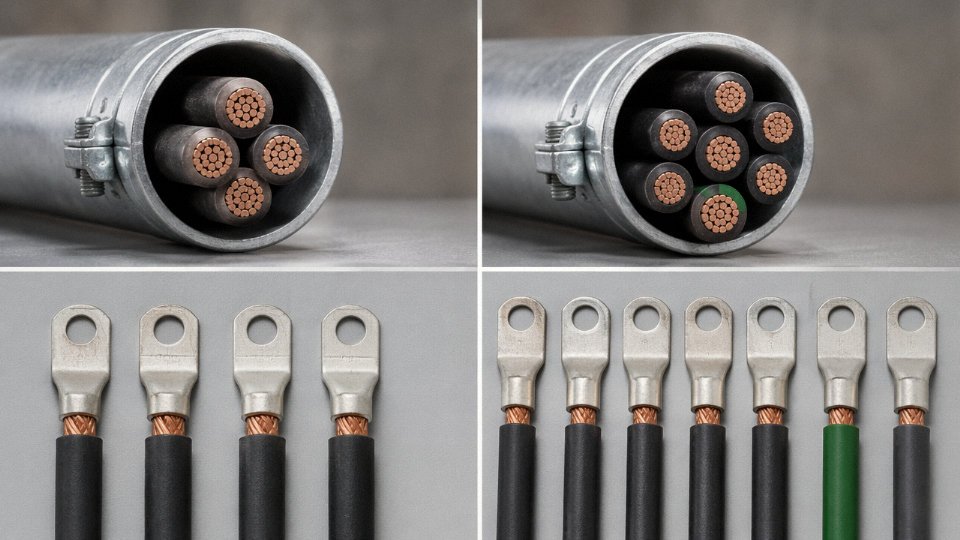
The termination question is equally important and often overlooked. Compression-type ferrules and some older screw-terminal blocks are torque-rated for a defined wire count and packing geometry. Fine-wire conductors can extrude sideways under compression if the ferrule isn’t sized for Class 5 strand count. Always check the terminal manufacturer’s acceptance data for fine-wire conductors, and if you’re using bootlace ferrules — which you should be for any Class 5 conductor going into a screw terminal — verify the ferrule is rated for the actual wire count you’re terminating.
What is the difference between IEC 60228 Class 5 and Class 6?
Class 6 takes the fine-wire philosophy further. Individual wire diameters are smaller still, the strand count per conductor is higher, and the construction is optimized for applications where the cable is physically handled continuously — welding leads, hand tools, portable equipment that gets coiled and uncoiled every shift. Class 5 covers the vast majority of industrial flexible cable applications: machine connections, drag chains, robotic tethers, flexible conduit drops. If your application involves a technician physically gripping and routing the cable repeatedly, or bend radii tighter than Class 5 allows, then Class 6 is worth specifying. For most plant-floor machinery, Class 5 is the right stop.
Does Type 5 cable cost significantly more than Type 4?
Typically 5–15% more in finished cable price at equivalent copper cross-section and insulation system. How much depends on order volume, insulation type, and whether you’re sourcing from an integrated manufacturer or a trading intermediary. At high volumes — say, a multi-year machine builder supply contract — that premium compresses considerably. The raw copper content is nearly identical; the cost difference is almost entirely in the wire drawing and stranding operation.
Type 5 and Type 4 cables of the same cross-section carry the same rated current under IEC 60364-5-52True
Ampacity under IEC 60364-5-52 is determined by conductor cross-section and the thermal environment (installation method, ambient temperature, grouping). Conductor class — the number and diameter of individual wires — does not change current-carrying capacity for equivalent cross-sections.
Does Type 5 conductor affect current-carrying capacity compared to Type 4?
No. Ampacity under IEC 60364-5-52 is a function of cross-section and thermal environment — installation method, ambient temperature, cable grouping. A 6 mm² Class 5 conductor and a 6 mm² Class 4 conductor carry the same rated current. The fine-wire geometry changes mechanical behavior, not thermal or electrical capacity. This confusion occasionally surfaces in panel shop specs where someone writes “use Type 5 for higher current” — that’s simply wrong.
What cable standards specify Type 5 conductors for industrial machinery?
IEC 60204-1 covers the safety of machinery electrical equipment and references flexible cables for machine connections, pointing implicitly toward Class 5 for any moving or frequently repositioned conductors. IEC 60227 and IEC 60245 specify conductor class requirements within their respective cable type designations. The EN 50525 series, which covers harmonized flexible cables across European markets, similarly ties conductor class to application category. Most machine tool and industrial robot cable standards — including application specifications from major robot platform builders — require minimum Class 5 for any conductor in a moving axis or tethered arm assembly. If you’re writing a machine spec for export to multiple regions, citing IEC 60228 Class 5 directly in the conductor specification is cleaner than relying on derived references.
How do I specify Type 5 cable correctly in a purchase order?
Reference IEC 60228 Class 5 explicitly — don’t leave it at “flexible cable” and assume the supplier will interpret that correctly. State the conductor cross-section in mm², copper type (bare or tinned, the latter being worth specifying for humid or chemically aggressive environments), the insulation and jacket system (PVC, XLPE, PUR, or silicone depending on temperature and chemical exposure), voltage rating, and any additional requirements such as shielding, oil resistance, or drag-chain duty rating. A PO that simply reads “2.5 mm² flexible cable” is an invitation for a Class 4 delivery. Jinda’s technical team can provide a compliant specification sheet template covering IEC 60228 Class 5 construction parameters on request.