Specify the wrong control cable for a machine tool, a packaging line, or a drive panel and you will find out quickly — nuisance faults first, then intermittent trips, then a failed batch or an unplanned line stop at the worst possible shift. The root cause usually traces back to a mismatch between cable construction and the actual electrical environment: unshielded cable running next to a VFD, signal pairs sharing a conduit with power conductors, or a PVC outer jacket that softens and cracks inside a 70 °C enclosure. Those are not edge cases. They show up regularly enough that maintenance teams stop chasing them individually and start replacing cable categories wholesale — which is an expensive lesson compared to specifying correctly the first time.
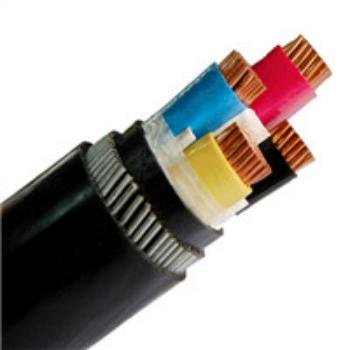
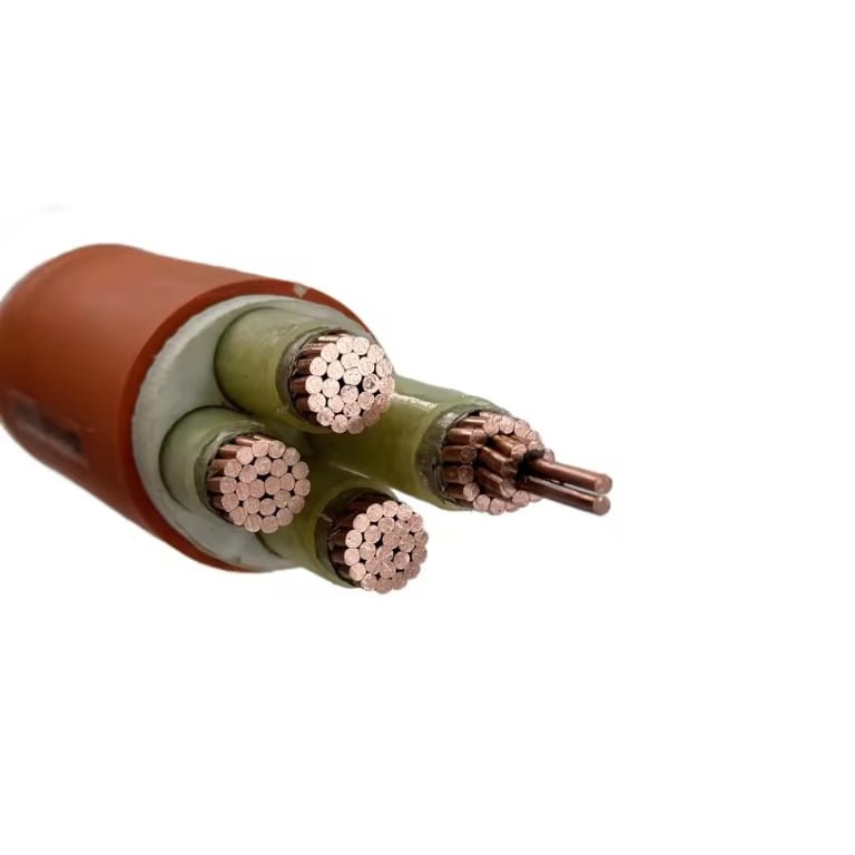
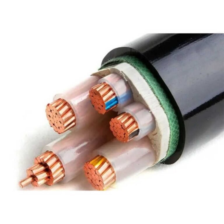
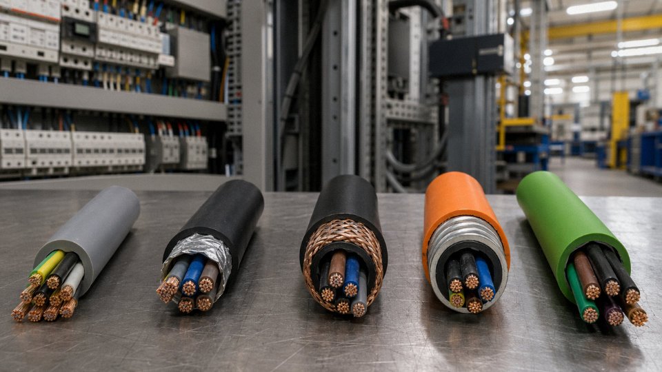
Control cables are purpose-built multicore cables used to carry low-voltage signals, command circuits, and instrumentation data between controllers, sensors, actuators, and switchgear. The main types are unshielded control cable, foil-shielded, braid-shielded, combination-shielded, armored, and flexible control cable — each differing in conductor count, cross-section (typically 0.5 mm² to 10 mm²), shielding construction, jacket material, and the governing standard (IEC 60227, IEC 60502, or UL 508) applied to the end market.
What makes this genuinely complicated is that “control cable” on a datasheet covers a wider range of constructions than most procurement lists acknowledge. A braid-shielded cable rated for 85–98% optical coverage in a VFD cabinet is a fundamentally different product from a plain unshielded harness running a limit switch — even if both show up under the same line item on a BOM. The differences in construction directly determine whether your control system runs clean or spends its life generating ghost faults, and understanding those differences is what the rest of this guide covers.
Unshielded vs. Shielded Control Cables: Choosing the Right EMI Protection Level
Not every control cable needs a shield. That’s worth stating plainly, because over-specifying shielding adds cost, bulk, and termination complexity without buying you anything if the electrical environment doesn’t warrant it.
When Unshielded Cable Is the Right Call
In low-noise environments — a simple relay logic panel, a lighting contactor circuit, an HVAC motor starter running short home-runs back to a local control panel — unshielded control cable does the job cleanly and costs noticeably less. Signal runs under roughly 10–15 meters carrying discrete 24 VDC or 120 VAC switching signals have enough noise margin that even moderate ambient interference doesn’t cause false triggers. Twisted construction in the conductors helps reject common-mode noise even without a metallic shield. Specifying shielded cable here is money spent on nothing.
The calculus changes fast once you introduce variable frequency drives, servo amplifiers, or any high-frequency switching topology within a few meters of the control wiring.
Aluminum-Polyester Foil (Al/PET) Shields
Foil shields — an aluminum layer bonded to a polyester film, wrapped longitudinally around the cable core — provide 100% optical coverage by geometry. That’s their main selling point. They attenuate high-frequency noise effectively, typically above 1 MHz, which makes them adequate for many PLC I/O and sensor signal applications.
The limitations are real, though. Foil tears under repeated flexing; install it in a cable track that cycles a few thousand times and you’ll find stress cracks at the bends. Termination requires a drain wire (a bare or tinned copper conductor running in contact with the foil), and a poorly landed drain wire — tucked back rather than properly grounded — turns the shield into a pickup antenna rather than a rejection barrier. Always terminate the drain wire at the control panel end only for analog signals, and keep that pigtail as short as physically possible.
Tinned-Copper Braid Shields
Braid shields are woven from tinned copper strands, typically achieving 85–98% optical coverage depending on braid angle and strand count. What they sacrifice in coverage compared to foil, they more than recover in mechanical resilience and low-frequency attenuation performance. A braid handles repeated bending cycles — servo motor feedback cables, pendant cables on cranes, drag-chain applications — without degrading electrically.
For VFD output circuits and servo drive signal cables, braid is usually the minimum acceptable shield. The switching frequencies from modern IGBTs generate significant interference in the 10 kHz–1 MHz range, right where braid shields perform best.
Combination Shielding: Foil Plus Braid
Wrap a foil first, then braid over it, and you cover the full frequency spectrum. The foil handles high-frequency noise above 1 MHz; the braid suppresses lower-frequency interference and provides the mechanical protection the foil alone can’t deliver. Industrial robots, precision analog instrumentation loops, and PLC I/O cables in heavy manufacturing environments typically require this construction. It costs more — roughly 20–40% more than foil-only, depending on braid coverage and conductor count — but in a robot welding cell running 600 A welding current three meters from the teach pendant cable, it’s not optional.
Individual Pair Shielding for Multi-Pair Instrumentation Cables
Overall shielding protects the cable bundle from external interference but does nothing for crosstalk between pairs inside the cable. For analog 4–20 mA or 0–10 V loops running as multiple pairs in a single cable jacket, you need per-pair foil shields, each with its own drain wire. Without individual pair shielding, a loop carrying a fast-switching signal can induce millivolt-level errors into an adjacent slow analog loop — enough to cause setpoint drift in a temperature or pressure control application.
EMI Attenuation by Shield Type and Frequency
| Shield Type | 10 kHz | 100 kHz | 1 MHz | 10 MHz |
|---|---|---|---|---|
| Unshielded (twisted) | 0–5 dB | 0–5 dB | 0–3 dB | 0–2 dB |
| Al/PET foil only | 10–20 dB | 25–40 dB | 40–55 dB | 50–60 dB |
| Tinned-copper braid (85–95%) | 20–35 dB | 30–45 dB | 35–50 dB | 40–55 dB |
| Foil + braid combination | 30–45 dB | 45–60 dB | 55–70 dB | 60–75 dB |
Actual attenuation depends on termination quality, grounding method, and cable geometry. Poor grounding can reduce effective attenuation by 15–30 dB regardless of shield type.
Grounding: Where Most Shield Failures Actually Happen
Single-point grounding — bonding the shield at one end only — is the correct approach for analog signal cables. It prevents ground loop currents from flowing through the shield, which would induce noise rather than reject it. Ground both ends of a shield on a 4–20 mA loop and you’ve created a path for ground potential differences to ride directly onto your signal.
Digital signal cables (fieldbus, Ethernet, RS-485) are a different story. They often benefit from multi-point grounding because the signal frequencies are high enough that the shield needs a low-impedance path to ground at both ends to function as an effective RF barrier. The right answer depends on the signal type, not a blanket rule.
Improper drain wire termination can reduce shield effectiveness by 15–30 dB, effectively negating the cost of the shielded cable.True
A poorly landed or floating drain wire creates impedance discontinuities that allow EMI to couple into the conductor bundle rather than be diverted to ground. This is well-documented in IEC 61000-5-2 installation guidelines and observed routinely in plant EMC troubleshooting.
One operational warning worth flagging: in practice, the single most common EMI problem I’ve seen traced back to control cables isn’t shield type selection — it’s a maintenance electrician who re-terminated a shielded cable after a repair and left the drain wire floating or looped it back under the wrong terminal screw. Specify the right shield, then make sure your termination procedures and commissioning checklists enforce the grounding requirement every single time.
By Conductor Construction: Solid, Stranded, and Flexible Fine-Wire Control Cables
Conductor construction is one of those spec decisions that gets made early and regretted late — usually when a cable fails in a drag chain at 400,000 cycles or when a solid conductor cracks at a terminal block after a machine gets repositioned three times during commissioning. Getting it right means understanding what IEC 60228 actually defines and, more practically, what each class survives in daily plant use.
Solid Conductors (Class 1)
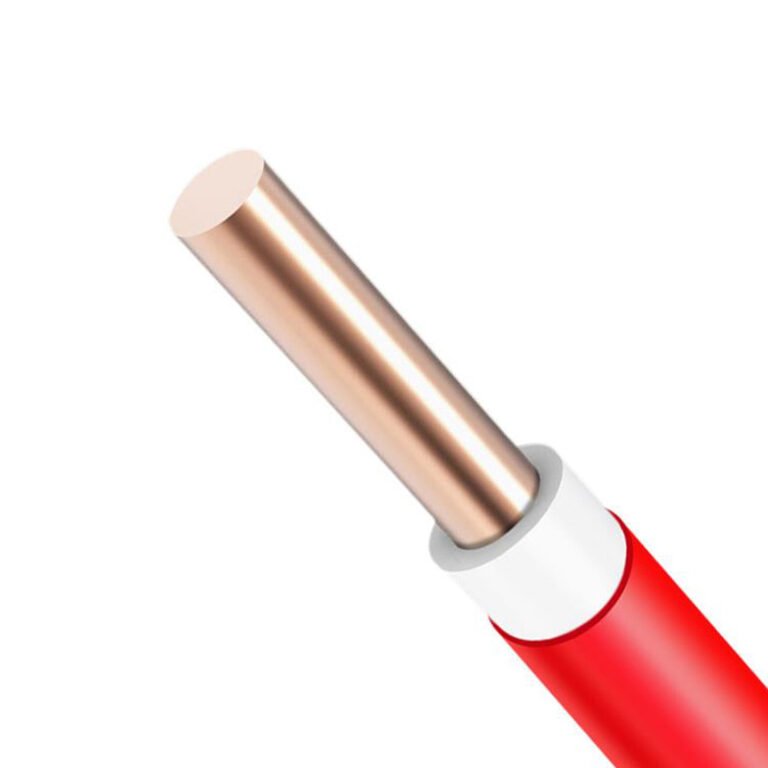
Solid conductors are a single, unbroken copper wire. They’re cheaper to manufacture, they terminate cleanly in screw-cage and ferrule-type terminals without the strand splaying that plagues improperly prepped stranded wire, and they hold their shape. For building automation panels, control cabinet wiring that never moves, and HVAC instrumentation runs embedded in conduit, solid conductors are a perfectly sensible choice. The contact resistance at termination points is consistently low because there’s no strand-movement effect over time.
The absolute constraint: zero tolerance for repeated bending. Flex a solid 1.5 mm² conductor a few dozen times at the same point and you’ll see work-hardening cracks. Fixed installation only. That’s not a limitation to design around — it’s just the physics of annealed copper.
Standard Stranded Conductors (Class 2)
Class 2 is where most industrial control cable lives. Seven-wire or 19-wire stranded construction gives enough flexibility to survive installation — pulling through conduit, routing around panel corners, occasional repositioning when maintenance crews need to shift a machine. The cost premium over solid is modest, and the termination behavior in most industrial terminals is still acceptable, especially with proper ferrule crimping.
The word “flexible” in marketing materials sometimes overstates what Class 2 can handle. It is not a dynamic flexing cable. Use it in a cable carrier and you’ll likely see fatigue failures somewhere between 300,000 and 600,000 bend cycles depending on bend radius and travel speed — sometimes sooner if the installation geometry is poor. That sounds like a lot until you realize a machine cycling four times per minute hits 500,000 cycles in under three months.
Finely Stranded Flexible Conductors (Class 5 and Class 6)
Class 5 and Class 6 cables use a much higher count of thinner individual wires — sometimes 49 or more strands in a conductor that would be seven wires in Class 2. The smaller strand diameter reduces the stress at each wire’s outer fiber during bending, which is the fundamental mechanism behind fatigue life extension.
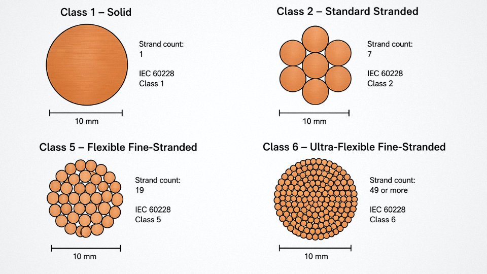
In a cable carrier application with a 50 mm bend radius and a 0.5-second cycle, a Class 6 flexible cable routinely exceeds 10 million flex cycles. A Class 2 cable under identical conditions may not reach 500,000. That’s not a marginal difference — it’s a service life ratio of 20:1 or more. For a robot arm running three shifts, that gap is the difference between a cable that outlives the machine and one that becomes a recurring maintenance line item.
Minimum bend radius is where conductor class and jacket material interact. A Class 6 conductor with a stiff PVC jacket doesn’t give you the full benefit of fine stranding. Proper drag-chain cables pair Class 5 or Class 6 conductors with a polyurethane or specially compounded PVC jacket that flexes cooperatively. The rule of thumb most cable vendors quote is a dynamic minimum bend radius of 7–10× the cable outer diameter for carrier systems, though the actual figure depends on the jacket compound, the number of conductors, and whether the cable is shielded.
Tinned Copper Strands
Bare copper oxidizes. In a dry cabinet environment that’s rarely an issue, but in food processing facilities with regular washdowns, offshore platforms, coastal installations in humid climates, or anywhere condensation is a seasonal reality, oxidation at the strand surfaces progressively increases conductor resistance. Tinned copper strands solve this — the tin coating acts as a barrier, and well-tinned strands will maintain stable contact resistance across years of service in conditions that would leave bare copper looking green and unreliable.
Tinned conductors eliminate oxidation-related resistance creep in high-humidity control cable installationsTrue
Tin plating on individual copper strands forms a protective oxide layer (SnO₂) that is far more stable than copper oxide (Cu₂O/CuO), maintaining consistent conductor resistance over time in humid or chemically aggressive environments. This is well-established in IEC and industrial cable specifications.
Tinning adds a small cost — roughly 5–12% on conductor material depending on current copper and tin pricing — but for the right environment it’s not optional, it’s maintenance cost avoidance.
Matching Cross-Section to Signal Type
Cross-section selection isn’t just about current capacity. On long 4–20 mA analog runs — say, a transmitter 400 m from the control room — using 0.75 mm² instead of 1.5 mm² can introduce enough loop resistance to cause measurable signal error at the receiver end, depending on source impedance. Thermocouple extension cable is even less forgiving: contact resistance at any termination point introduces a thermal EMF error that looks identical to a real temperature shift. For those applications, clean, correct termination of adequately sized conductors matters more than people expect.
Motor contactor control circuits carrying 24 VDC or 110 VAC coil currents through 2.5 mm² conductors are much more tolerant, but the wrong cross-section in the wrong application — particularly under-specified conductors in high-cycle solenoid wiring — will show up eventually as heat at terminals.
By Insulation and Jacket Material: PVC, XLPE, LSZH, and Specialty Compound Control Cables
Material selection is where a lot of procurement decisions go quietly wrong. Engineers specify a cable gauge and conductor count correctly, then default to standard PVC because it’s familiar and cheap — and six months later they’re dealing with jacket cracking in a cold outdoor enclosure, or failing a fire-safety audit on a metro project. The insulation and jacket compound isn’t an afterthought; it defines the cable’s operational envelope.
PVC: The Baseline That Covers Most, But Not All, Applications
Polyvinyl chloride remains the dominant insulation and sheathing material worldwide, and for good reason. It’s cost-effective, electrically robust, and straightforward to process. Oil-resistant grades — PVC/A and PVC/D per IEC 60227 — handle incidental machine-tool coolant contact reasonably well. Standard PVC control cables typically operate across roughly -15 °C to +70 °C continuous, which covers the majority of indoor industrial switchgear and automation panels.
The real limitation surfaces in fire scenarios. PVC releases hydrogen chloride gas when it burns — corrosive, toxic, and capable of destroying nearby electronics even after the fire is out. In an open factory bay with good evacuation routes, that’s a manageable risk. In a tunnel, a ship’s cable tray, or a crowded data center, it isn’t.
XLPE: Better Thermal Headroom and Cleaner Signal Behavior
Cross-linked polyethylene pushes continuous temperature rating to 90 °C, with some specialty grades reaching 105 °C. The cross-linking process fundamentally changes the polymer structure, which is why XLPE resists deformation under sustained load better than PVC of equivalent wall thickness. Chemical resistance improves meaningfully too — acids, alkalis, and many solvents that attack PVC over time leave XLPE largely unaffected.
There’s a signal-integrity angle worth noting for instrumentation runs: XLPE has a lower dielectric constant than PVC, which reduces capacitive loading on long cable runs feeding analog sensors or 4–20 mA loops. The difference is subtle in short runs but can matter in process plants where signal cables stretch 200–400 m between field instruments and control rooms.
LSZH: Non-Negotiable in Confined, Occupied Spaces
Low smoke zero halogen — sometimes written LSOH — is not an upgrade you choose for performance. It’s a regulatory and life-safety requirement in enclosed environments. EN 50525-3-11 governs LSZH control cable construction, and IEC 60332 series tests verify flame propagation behavior. Metro systems, offshore platforms, passenger vessels, airport terminals, and modern data centers typically mandate LSZH by specification or local code.
LSZH cables produce significantly less smoke and no halogen acids compared to PVC cables under fire conditionsTrue
LSZH compounds are formulated from halogen-free polymers such as polyolefin blends; when burned, they release minimal smoke and no hydrogen chloride, verified under IEC 60754 and EN 50267 test methods.
The trade-off is real: LSZH compounds are generally stiffer and less abrasion-resistant than equivalent PVC, and they cost more — expect to pay a noticeable premium depending on cable complexity and order volume.
Silicone Rubber: When Everything Else Melts
If you’re running signal cables through a steel mill reheat furnace area, a glass plant, or an automotive paint-oven conveyor zone, silicone rubber is usually the only practical choice. Operating range runs from roughly -60 °C up to +180 °C continuous, with short-term excursions tolerated beyond that in many grades. It stays flexible at temperatures where PVC has long since gone brittle.
One operational caveat: silicone jackets are mechanically soft and tear relatively easily under abrasion. In high-heat environments that also involve mechanical contact — dragging over steel edges, for instance — consider a silicone-insulated, glass-braid-served construction rather than plain silicone.
Polyurethane Jackets: The Right Answer for Flex and Filth
PUR outer sheaths don’t often appear in basic cable specs, but in food processing plants, outdoor mobile machinery, and drag-chain applications, they earn their place. Resistance to hydrolysis, microbes, cleaning chemicals, and oils is substantially better than PVC. Abrasion resistance is also higher — relevant when cables are repeatedly dragged or flexed against guide rails.
In drag-chain installations specifically, the jacket compound and conductor stranding work together. A finely stranded conductor inside a PUR jacket can survive tens of millions of flex cycles; the same cable with a standard PVC jacket often shows jacket cracking within the first year of demanding operation.
Fluoropolymers: PTFE, FEP, PFA — Maximum Performance, Maximum Cost
PTFE, FEP, and PFA insulations sit at the top of the performance ladder and the price list simultaneously. Dielectric loss is extremely low across wide frequency ranges, chemical inertness is essentially total, and operating temperatures span from cryogenic conditions to well above +200 °C depending on grade. Semiconductor fabrication, chemical dosing systems, and precision instrumentation circuits justify the cost. General-purpose factory automation does not.
Material Selection Quick Reference
| Environment / Requirement | Insulation | Jacket |
|---|---|---|
| Standard indoor panel / switchgear | PVC | PVC |
| Outdoor UV exposure, 90 °C rating | XLPE | XLPE or UV-stabilized PVC |
| Tunnel, metro, offshore, data center | LSZH | LSZH |
| Extreme heat (steel mill, paint oven) | Silicone | Silicone or glass braid |
| Food & beverage, outdoor mobile, drag-chain | PVC or XLPE | PUR |
| Semiconductor, chemical dosing, HF signal | PTFE / FEP / PFA | PTFE / FEP or PFA |
| Oil-saturated machine tool environment | PVC/D (IEC 60227) | PVC/D or PUR |
Selecting the right compound is ultimately about matching the cable’s worst-case environment, not its average environment. A cable that survives 95% of its service conditions but fails in the other 5% — a cleaning cycle, a temperature spike, a fire evacuation scenario — is a specification error, not a materials-supply problem.
By Application Environment: Control Cables for Industrial Automation, Process Plants, and Infrastructure
Environment drives specification far more than most procurement checklists acknowledge. A cable that performs flawlessly inside a clean machine cabinet will fail within a season in a cable tray running through a petrochemical plant — not because the manufacturer cut corners, but because the design brief was wrong from the start. What follows organizes the main control cable families by where they actually live and what that environment demands of them.
Industrial Automation and Machine Building
This is the highest-volume segment, and the specs are relatively well-standardized. Multi-core flexible cables connecting PLCs, sensors, actuators, and servo drives typically run 18 to 37 cores at 0.75 to 1.5 mm², Class 5 fine-stranded conductors, with an overall braid shield and either a PVC or PUR outer jacket. IEC 60204-1 sets the machinery safety framework, which in practice means the cable also needs to clear flame-retardancy requirements — usually IEC 60332-1 at minimum, and IEC 60332-3 for bunched installations in cable ducts.
PUR jacketing gets specified when the cable routes through areas with cutting fluid, hydraulic oil mist, or mechanical abrasion — on a CNC machining center, for instance, the cable managing spindle encoder feedback takes a constant beating that PVC won’t survive beyond a year or two. PVC is fine in cleaner environments and costs noticeably less, so there’s no point over-specifying.
Process Industry: Oil, Gas, Chemical, and Petrochemical
Armored construction is essentially non-negotiable here. Steel wire armour (SWA) handles the mechanical loads in cable trenches, where heavy backfill, vehicle crossings, or thermal cycling can crush unarmored cable. Steel tape armour (STA) is lighter and suits indoor tray runs in chemical plants where the primary concern is rodent damage or accidental impact rather than sustained crush load.
Insulation is where process plants diverge sharply from automation: XLPE handles continuous temperatures up to roughly 90°C and resists a broad range of chemicals; EPR goes further still in high-temperature zones near heat exchangers or furnace areas. ATEX and IECEx certification matters everywhere cables enter Zone 1 or Zone 2 classified areas — and in practice this also means checking that the installed cable gland and termination method is compatible, because a certified cable with a non-compliant gland voids the installation.
SWA control cables installed in cable trenches require no additional mechanical protectionFalse
SWA provides mechanical protection against crush and impact, but cables in trenches subject to repeated vehicle crossing or ground movement typically still need concrete tile protection above the cable or installation inside conduit, depending on the depth and site-specific risk assessment.
Building Management Systems and HVAC
Core counts drop considerably here — 2 to 12 cores is typical — and the dominant specification driver shifts from EMI to fire performance. Circuit integrity under fire (IEC 60331) is mandatory for emergency control circuits: smoke extract dampers, fire door release, emergency lighting control. LSZH jackets are written into national codes in most of Europe, the Middle East, and increasingly Southeast Asia for occupied buildings. In my experience, building contractors sometimes push back on LSZH for HVAC controls that aren’t on emergency circuits, trying to substitute cheaper PVC — worth pushing back on, particularly in basement plant rooms with limited ventilation.
Railway, Transit, and Signaling
EN 50264 defines the fire, smoke, and toxicity (FST) performance envelope for rolling stock cables. Vibration resistance is the other non-negotiable: connections that loosen under constant mechanical stress generate intermittent faults that are genuinely difficult to diagnose in the field. EMC screening is specified on signal cables running alongside traction power — the interference environment in a rail depot is severe enough that an unscreened cable picking up 50 Hz harmonics can generate spurious signals in signaling electronics.
Renewable Energy
Wind turbine nacelle-to-hub cables are a distinct cable type: torsion-resistant construction handles the continuous twisting as the nacelle yaws, and the conductors need to survive millions of flex cycles over a 20-year design life. For ground-mounted solar farms, UV-stabilized XLPE or LSZH outdoor-rated jackets handle sun exposure; rooftop installations near occupied spaces favor halogen-free compounds specifically to limit combustion products if a fault causes a cable fire.

Marine, Offshore, and Mining
IEC 60092-376 governs marine control cables: tinned conductors to resist corrosion in salt-spray environments, oil and mud resistant outer sheaths, overall screen, and typically armored construction on deck or in exposed cable routes. The design brief is partly about confined spaces — a cable fire aboard a vessel is a different risk profile than a cable fire in an open industrial yard.
Mining trailing cables sit at the extreme end of mechanical demand. Highly flexible construction allows the cable to coil and uncoil with haulage equipment repeatedly without fatiguing conductors. Anti-static jacket compounds are specified in methane-risk environments; a jacket that can build and discharge static charge becomes an ignition risk. Flame retardancy is specified to stringent standards — IEC 60332-3 category A in most modern mining codes — because a fire propagating along a cable bundle in an underground tunnel is one of the worst-case scenarios in the industry.
Instrument Cables, Thermocouple Extension Cables, and Data Transmission Control Cables
These are the cable types where getting the specification wrong doesn’t just cause a nuisance fault — it corrupts your process data, throws off temperature readings by tens of degrees, or drops a fieldbus segment entirely. The margins are tighter here than anywhere else in the cable schedule.
4–20 mA Instrument Cables and ISTP Construction
Analog instrumentation loops running 4–20 mA are the backbone of most process plants, and the cable carrying those signals needs individually shielded twisted pairs (ISTP) — one drain wire and foil shield per pair, not a single overall shield wrapped around six conductors. The twisting rejects common-mode noise; the individual shield stops crosstalk between pairs sharing a conduit or tray. For longer runs — say, 200 to 400 meters from a field transmitter back to a marshalling cabinet — capacitance matters more than most people expect. Low-capacitance ISTP cables typically spec below 60–80 pF/m between conductors; standard multi-pair cable might run 100–150 pF/m, which starts distorting the signal waveform on anything over about 150 m in a noisy environment. ISA-5.1 loop wiring practice is the reference document most instrument engineers use, and it’s worth reading even if your project is technically governed by IEC standards.
Thermocouple Extension and Compensating Cables
This is where procurement errors are genuinely expensive. A Type K thermocouple pair uses Chromel and Alumel alloys; if you run that signal back to the panel through copper conductors — even just through a junction box terminal strip — you’ve introduced a spurious EMF at every dissimilar-metal junction. The thermocouple has no idea where the measurement junction is supposed to be.
Thermocouple extension cables must use conductors made from the same alloy (or a designated compensating alloy) as the thermocouple element all the way back to the reference junction at the instrument input.True
IEC 60584-3 specifies conductor materials for each thermocouple type precisely to prevent parasitic EMFs at intermediate junctions. Substituting copper between field and panel introduces a second, uncontrolled thermocouple junction that creates a temperature-dependent measurement error.
Each type — K, J, T, E, N, and the platinum types S, R, B — has its own required conductor material under IEC 60584-3. Types S, R, and B are expensive; their extension cables often use compensating alloys that match the thermocouple’s output over a limited temperature range rather than the full platinum-rhodium alloy, which reduces cost without sacrificing accuracy in the compensation zone. Specify clearly whether you need extension grade or compensating grade, because suppliers will sometimes substitute if the purchase order just says “thermocouple cable, Type K.”
RTD Cables and the Lead Resistance Problem
RTD measurements work by detecting resistance changes in the milliohm range. Three- and four-wire RTD cables exist specifically to cancel out lead resistance error through Wheatstone bridge or Kelvin sensing techniques, but this only works if the conductors are closely matched in resistance — meaning the same cross-section, same alloy, same length. A four-wire PT100 circuit with mismatched conductors can show a fixed offset of a degree or two, which in pharmaceutical or food processing applications is a calibration failure. Shield the cable; even small induced voltages corrupt a 100 Ω measurement.
Fieldbus and Industrial Ethernet Cables
PROFIBUS DP cable is not just “shielded twisted pair.” The standard calls for a characteristic impedance of 150 Ω ±20 Ω, violet jacket for identification, and a specific conductor gauge — typically 0.64 mm diameter solid copper. Substitute a generic 120 Ω Ethernet cable and the segment reflections will cause intermittent faults that take days to trace.
DeviceNet uses a flat or round hybrid construction: two signal conductors, two power conductors (24 V bus power), each pair shielded, color-coded per the ODVA specification. EtherNet/IP running over Cat 5e or Cat 6 in an industrial environment needs a PUR outer jacket, not PVC — PVC gets brittle in moderate flexing and embrittles faster around VFD panels that run warm year-round.
HART-compatible analog cables are essentially good-quality ISTP instrument cables. HART signals ride at 1,200 Hz on the 4–20 mA loop, so cable capacitance matters again; high-capacitance cable attenuates the HART burst enough that the modem can’t decode it reliably beyond certain distances.
Encoder Feedback and High-Flex Drag-Chain Data Cables
Encoder cables for servo drives operating at 100 kHz to 1 MHz pulse rates need conductor-to-conductor capacitance below roughly 100 pF/m — often closer to 70–80 pF/m in practice — or the pulse edges smear and the drive loses position count. These cables also live in drag chains, which means fine-stranded conductors, a jacket with good cold-flex properties, and a shield construction that won’t fracture after a few million flex cycles. Combination foil-plus-braid shields work here; foil alone tends to crack at the flex radius over time.
Hybrid drag-chain cables combining power cores and encoder or data pairs in a single jacket do reduce track fill and simplify routing on CNC machines and articulated robots, but the power conductors must be separated from signal pairs by a dedicated inner shield or physical barrier within the cable. Otherwise, the motor switching transients induce noise directly onto the signal pairs regardless of the outer shield. Some cable manufacturers wind a grounded separator tape between the power bundle and the signal bundle; check the construction drawing, not just the catalog description.
A Procurement Distinction Worth Enforcing
“Instrumentation cable” and “control cable” are used interchangeably in a surprising number of purchase orders, and they shouldn’t be. Control cables are designed to carry relay switching currents, solenoid coil loads, and indicator lamp circuits — circuits where the signal level is high enough that a bit of capacitive noise pickup is irrelevant. Instrumentation cables are optimized for low-level analog and digital signals where impedance, capacitance, and shield isolation are the primary design parameters. Ordering a standard multi-conductor control cable for a 4–20 mA loop because both descriptions fit loosely is a common enough mistake that it’s worth putting explicit language in your cable schedule: state the signal type, the shield configuration, and the capacitance limit. Don’t leave it to the supplier to interpret.
How to Read a Control Cable Designation and Match It to International Standards
Cable datasheets are full of alphanumeric strings that look like random letters until you know the system. Once you do, they carry a surprising amount of engineering information in a compact form — and misreading even one character can result in ordering the wrong product.
Decoding the IEC/VDE Structure: A Worked Example
Take YSLY-JZ 7G1.5. Each element has a specific meaning:
- Y — PVC insulation on the conductors
- SL — PVC outer jacket, flexible grade (the “SL” combination denotes a harmonized flexible cable construction under VDE 0293 lineage)
- Y — confirming PVC as the jacket compound
- JZ — this suffix means the cable is assembled with an earth/green-yellow core included, configured for equipment connection (as opposed to JB, which indicates a cable without earth or with a different core arrangement)
- 7 — seven conductors total
- G — includes a protective earth conductor (green-yellow); if this were an “X” instead, all conductors would be the same non-earth color
- 1.5 — 1.5 mm² cross-section per conductor
So the full read: seven-conductor flexible PVC control cable with earth core, 1.5 mm² per conductor. It slots comfortably into IEC 60227 for rated voltages up to 300/500 V, and you’ll see it everywhere in European switchgear panels and machine tool wiring.
Adding the Shield: YSLCY-JZ 4G1.0
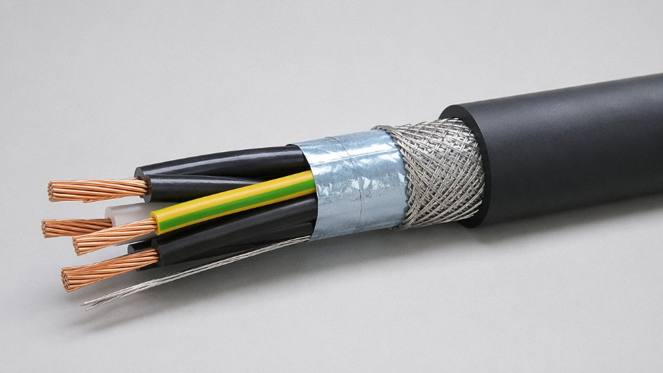
Introduce a C after SL — giving YSLCY-JZ — and you’ve added a copper braid screen around the cable core, before the outer jacket. That single letter changes the cable’s application profile entirely. A four-conductor 1.0 mm² shielded flexible cable of this type is a common choice for servo drive encoder feedback or position sensor wiring in CNC router installations, where VFDs and servo amplifiers generate enough radiated noise to corrupt a signal cable running nearby. The braid coverage on a proper YSLCY cable runs 85–95%, which gives useful attenuation across the frequency range typical of switching noise — generally 20–50 dB depending on frequency and the quality of shield termination at the drive end.
North American Designations: TC, ITC, PLTC, and UL 508
Across the Atlantic the logic shifts. UL 508 covers multi-conductor cables for industrial machinery, and NFPA 79 (Table 12.8.2 in recent editions) classifies acceptable cable types for machine wiring. The key marking types you’ll encounter on North American purchase orders are TC (Tray Cable, UL 1277), ITC (Instrumentation Tray Cable, UL 2250), and PLTC (Power-Limited Tray Cable, UL 13). Each carries different voltage, current-limitation, and installation requirements. A cable manufacturer supplying to both markets needs dual listings — IEC 60502 conformance plus a UL or CSA mark on the same cable reel. This is possible but adds lead time and cost, so confirm dual-certification requirements upfront in your RFQ rather than discovering the gap at customs.
A single control cable can carry both IEC and UL certifications, enabling compliant use in European and North American installations from the same product reel.True
Dual-certified cables are manufactured to satisfy both IEC 60502/60227 construction requirements and UL/CSA listing criteria. The manufacturer must maintain separate test records and marking compliance for each standard. This is commercially available but typically increases unit cost and minimum order quantity.
Color Coding: IEC 60446 vs. North American Conventions
This is a genuine source of confusion on international projects, and it causes real commissioning problems. Under IEC 60446, green-yellow is reserved for protective earth, blue is used for neutral or the common reference conductor, and remaining cores are assigned black, brown, grey, red, orange, violet, pink, and white in various combinations. North American practice typically uses green for earth, white or grey for neutral, and black for line conductors — with other colors filling out multi-conductor runs in no strictly standardized sequence beyond three-phase conventions.
When a European-designed panel is shipped to a North American facility, or vice versa, electricians unfamiliar with the other convention can and do miswire. The fix is straightforward: call out the color standard explicitly in your project specification, and require the cable supplier to confirm compliance. Don’t assume.
Voltage Designation Numbers
The paired voltage rating — such as 300/500 V or 0.6/1 kV — refers to two different values. The first number is the rated voltage conductor-to-earth (or conductor to metallic screen), and the second is conductor-to-conductor. So a 300/500 V cable is rated for 300 V to earth and 500 V between any two conductors.
For most 24 V DC and 115 V AC control circuits inside a panel, 300/300 V is technically sufficient but 300/500 V is the routine industrial specification because it provides headroom and is widely stocked. For circuits running at 230/400 V (standard three-phase European supply) you need at minimum 450/750 V or, more typically, 0.6/1 kV rated cable. Using a 300/500 V cable in a 400 V application is an insulation overstress situation — it may not fail immediately, but service life will be shortened and it won’t pass a proper inspection.
Armoring Suffix Codes
When cables run in open trays, underground ducts, or areas with mechanical abuse risk, armoring is added and coded in the designation:
| Suffix | Full Term | Typical Use |
|---|---|---|
| SWA | Steel Wire Armour | Direct burial, industrial tray, general mechanical protection |
| STA | Steel Tape Armour | Indoor duct runs, lighter mechanical duty |
| AWA | Aluminum Wire Armour | Weight-sensitive runs, areas where steel armour creates eddy-current concerns |
| DSTA | Double Steel Tape Armour | Higher crush resistance, often specified in road-crossing applications |
AWA is worth noting: in single-core AC cables, a steel wire armour can form a shorted magnetic circuit around the conductor, generating circulating currents and heating. Aluminum wire armour avoids this. It’s a detail that matters in power cables more than control cables, but if you’re specifying a single-core high-current control cable feeding a large actuator, it’s relevant.
The Practical Procurement Rule
A purchase order that says “5-core control cable, 1.5 mm²” is almost useless. A complete specification reads something like: YSLY-JZ 5G1.5, 300/500 V, IEC 60227, unarmored, grey PVC outer jacket, drum quantity 500 m. If shielding is required, add the shield type and coverage specification. If dual certification matters for your end market, state the UL or CSA listing requirement explicitly. Suppliers — including those operating across multiple production facilities — will substitute the closest available product if a parameter is absent. That substitution may be perfectly functional, or it may fail a site inspection. You won’t know until someone is standing on a job site with a cable that doesn’t match the drawing.
Write it down completely. Every parameter. It takes thirty seconds and saves real money.
Frequently Asked Questions About Control Cable Types
Can I use a power cable instead of a control cable for PLC wiring?
Not reliably, and in many jurisdictions not legally. Power cables are engineered around thermal endurance under sustained load current — their insulation wall thicknesses, conductor cross-sections, and core counts reflect that priority. What they don’t offer is the combination of small cross-sections (0.75–1.5 mm² is typical for PLC I/O), tight multi-core lay, and optional shielding that control circuits depend on. Run a standard two-core power cable back to a PLC input from a field sensor and you’ll likely pass electrical inspection — once. Over time, the absence of shielding in a noisy cabinet environment causes spurious triggering, and the oversized conductors make termination in small-pitch terminal blocks genuinely awkward.
IEC 60204-1, which governs electrical equipment on industrial machinery, draws a clear distinction between power wiring and control wiring. Using power cable for control circuits creates a compliance gap that an auditor or insurance assessor will flag. The risk isn’t just paperwork — it’s phantom faults at 2 a.m. that take a shift to diagnose.
What is the maximum number of cores available?
Standard IEC catalog designs go up to 61 cores, which covers most switchgear marshalling and multi-axis machine wiring jobs. Beyond that, manufacturers including Jinda can produce custom core counts for specialized applications — large substation cable termination panels, for instance, sometimes call for 80 or even 100 cores in a single run to reduce conduit congestion. As core count rises, conductor cross-section typically steps down (0.5 mm² or 0.75 mm² becomes the default) to keep the overall cable diameter within a range that’s actually installable through standard glands and conduit.
Standard IEC control cable designs are available with up to 61 cores, and custom configurations beyond that are offered by major manufacturers for specialized switchgear applications.True
61-core is a well-established upper limit in IEC multi-core control cable catalogs; custom productions beyond this are technically feasible and commercially available from full-range cable manufacturers.
How do I select the correct shield type for a VFD application?
Variable frequency drives are genuinely hostile to nearby signal wiring. PWM switching noise spans roughly 2 kHz up to 20 kHz or higher depending on the drive’s carrier frequency, and it couples capacitively and inductively into any unprotected cable running parallel in the same tray. A foil shield alone is often not enough here — foil is excellent at high frequencies but its drain wire termination creates a narrow, high-impedance connection that defeats the purpose under fast transients.
Braid-shielded or foil-plus-braid combination cable is the practical answer for VFD control wiring. The braid needs 85–95% optical coverage to be worth specifying. Equally important, and frequently ignored on the first installation: the shield must be terminated at both ends with 360° low-impedance connections — proper EMC cable glands, not a pigtail twisted back to a ground lug. A pigtail longer than about 50 mm starts acting as an antenna at VFD frequencies rather than a shield termination.
What is the difference between a screened and an armored control cable?
These solve completely different problems and get confused constantly. Screening is an electrical function — foil or braid around the signal cores to attenuate EMI. Armoring is a mechanical function — steel wire armor (SWA) or steel tape armor (STA) to resist crush loads, impact, and rodent attack in direct-burial or exposed-run installations. A cable can carry both constructions simultaneously (screened SWA is common in process plants), either one alone, or neither. Specifying armor when you needed shielding, or vice versa, is the kind of error that only shows up after the cable is pulled.
Are LSZH control cables always required in industrial buildings?
No — and the blanket assumption that LSZH is always better costs unnecessary money. The requirement depends on national building codes, cable installation method, and occupancy type. LSZH is mandatory in confined spaces where evacuation is slow: rail tunnels, offshore platform cable decks, public transit infrastructure, data centers in many jurisdictions. In a well-ventilated outdoor industrial cable tray at a petrochemical plant, standard flame-retardant PVC meeting IEC 60332-3 is usually acceptable and substantially cheaper. Check the applicable fire code for the specific installation, not a general industry preference.
How does conductor cross-section affect signal quality on long analog runs?
For 4–20 mA current loops, conductor resistance doesn’t corrupt the signal directly — the loop is current-controlled, so a higher loop resistance just reduces the headroom against the transmitter’s compliance voltage limit. The practical threshold is usually around 500–1,000 Ω total loop resistance depending on the transmitter, which translates to surprisingly long runs even at 0.5 mm². Voltage-mode signals (0–10 V) are a different story. Resistive drop is now a direct measurement error. For runs beyond roughly 100 m, 1.5 mm² is a reasonable minimum, and 2.5 mm² is worth considering beyond 200 m if you need to stay under 1% full-scale error without recalibrating the receiving end.
Can Jinda supply control cables certified to multiple international standards simultaneously?
Yes. Running a project that specifies IEC for the European scope and UL/CSA for equipment destined for a North American facility is a common procurement headache — two separate cable orders, two shipping schedules, two sets of paperwork. Jinda’s manufacturing operations across five production bases in China support certifications including IEC, CE, UL, CSA, GOST, and a range of regional approvals, and can produce cables carrying dual-certified markings in a single supply order. For large international EPC projects, that matters both for procurement simplicity and for the compliance documentation the end client needs at handover.
Procurement Checklist: Specifying and Sourcing Control Cables for International Projects
Getting a control cable specification wrong at the procurement stage is one of those mistakes that doesn’t announce itself until the project is already mid-installation — and by then, swapping out the wrong cable across a large cable tray system is an expensive, schedule-killing exercise. The checklist below is structured to catch the most common specification gaps before a purchase order gets issued.
Step 1 — Define the Electrical Parameters First
Start with voltage rating, signal type, and current load. A 300/500 V rating covers the vast majority of industrial control wiring, but analog 4–20 mA instrumentation loops, digital fieldbus signals, and multi-core power-feed circuits each have different conductor sizing logic. Allowable voltage drop matters more than most buyers realize — on a long cable run feeding a PLC input at 24 V DC, even a modest loop resistance across a 2.5 mm² conductor can push the signal voltage outside the acceptable input threshold if the run exceeds roughly 150–200 m, depending on current draw. Specify maximum conductor current, frequency range (particularly relevant for pulse or high-frequency encoder signals), and voltage drop limit before touching anything else. These parameters directly drive conductor cross-section selection across that 0.5 mm² to 10 mm² working range.
Step 2 — Map the Mechanical Environment
Fixed installation in a cable tray and a continuous-flex drag-chain application are not the same cable. A standard stranded Class 2 conductor will work fine in conduit; it will fatigue and fail within months in a moving chain. Specify whether the cable sees oils, coolants, UV exposure, or risk of crushing — these drive the jacket material decision far more than any catalogue default. If direct burial is involved, armoring and moisture-resistance become mandatory considerations, not optional upgrades.
Step 3 — Identify Fire and Hazardous Area Obligations Early
Confirm which fire performance standard applies before the specification is finalized — IEC 60332-3 for flame propagation in bunched cables, IEC 60331 if circuit integrity under fire is required. LSZH jacketing is often mandated in enclosed or poorly ventilated spaces regardless of what the base specification says. For ATEX or IECEx classified zones, anti-static properties and the specific zone/gas group must appear explicitly in the cable specification. These requirements are non-negotiable and cannot be retrofitted.
Step 4 — Define Shielding Requirements Against Actual Noise Sources
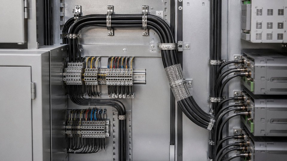
Walk the cable route on a drawing and mark every noise source: VFD panels, contactor banks, RF equipment, power bus bars. Individual pair shielding handles differential noise within a multi-pair cable; overall shielding handles external field ingress. In practice, a VFD-heavy environment with cables running parallel to motor feeder cables typically needs braid-shielded cables with 85–95% optical coverage, not the cheaper foil-only construction.
Step 5 — Write a Complete Cable Tag List
For every unique cable type, produce a full designation: rated voltage, core count and cross-section, conductor class, insulation material, jacket material, shield type and coverage, armoring if required, color coding standard (IEC 60757 or project-specific), and the applicable test standards. Submit this to at least two qualified suppliers for pricing comparison. Vague specifications produce incomparable quotes and disputes at inspection.
Step 6 — Evaluate Supplier Capability Objectively
ISO 9001 certification is the minimum bar. For larger projects — say, anything above 50 km of mixed cable types — confirm the supplier’s actual production capacity and lead time for your specific constructions, not just their advertised catalogue range. Ask for third-party test reports on fire performance and EMC shielding effectiveness; a reputable manufacturer will have these on file, not pending.
Third-party fire performance and EMC test reports should be available from qualified cable manufacturers without special request on standard catalogue constructions.True
Established manufacturers running IEC-compliant production maintain ongoing third-party type test records as part of certification maintenance. A supplier who cannot produce these promptly for standard constructions is a supply risk on a critical project.
Step 7 — Plan Logistics Around Standard Drum Lengths
Control cable ships on drums — typically 100 m, 500 m, or 1,000 m reels depending on conductor size and construction. Confirm cut-length tolerance upfront; a ±5% overrun on a large multi-line order adds up fast. For international projects buying multiple cable types simultaneously, consolidating shipments onto a single freight booking reduces both cost and customs complexity considerably. Jinda’s integrated sales and logistics structure handles exactly this kind of mixed-type consolidation for international buyers, which in practice cuts freight administration time and reduces the risk of partial deliveries holding up installation schedules.