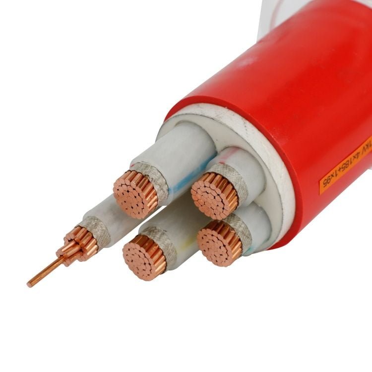
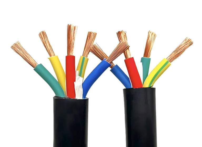
Specify the wrong cable type on a purchase order and you might not find out until commissioning day — when the insulation rating is too low for the ambient temperature, the flexible cable you ordered turns out to be rated for occasional flex rather than continuous motion, or the armoring spec doesn’t match the burial depth your civil team assumed. At that point you’re looking at reordering lead times measured in weeks, expediting freight costs, and in a worst case, a delayed production start that dwarfs whatever you saved on the original procurement.
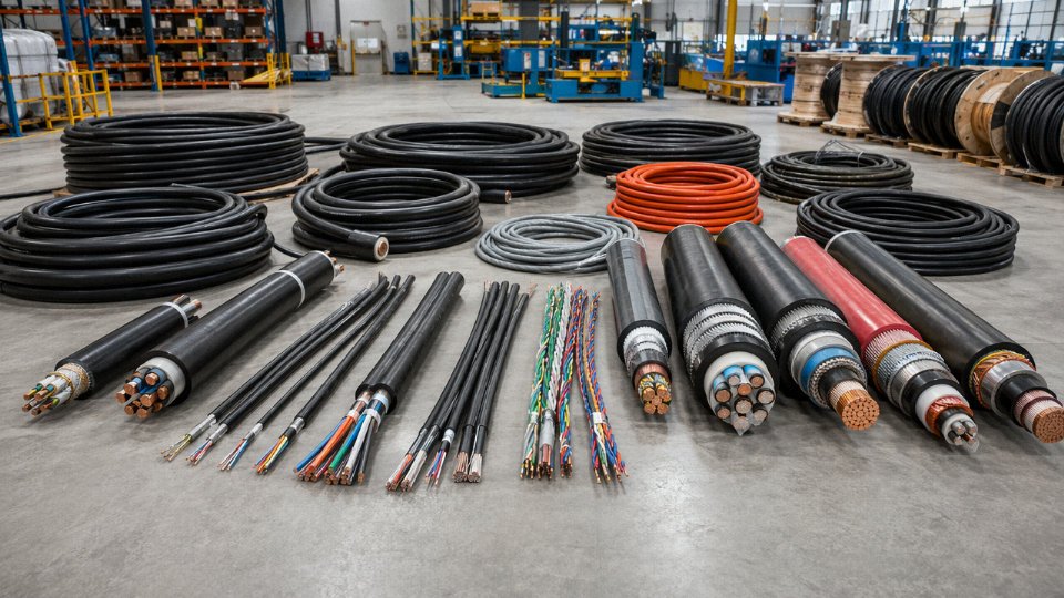
There are broadly seven to ten major cable categories depending on how you classify them — by application (power, control, data, instrumentation), by construction (armored, flexible, fire-resistant), or by voltage class (low, medium, high, ultra-high). Within those categories, IEC 60228 alone covers conductor cross-sections from 0.5 mm² up to 2,500 mm², with voltage ratings ranging from 300/500 V for standard wiring up to 500 kV for transmission-level underground links — meaning the total number of distinct cable types across all standards and industries runs well into the hundreds.
What makes this genuinely difficult is that the categories overlap in ways that catch even experienced procurement engineers off guard. A cable can be simultaneously a power cable, an armored cable, a flame-retardant cable, and a medium-voltage cable — and each of those descriptors pulls from a different standard, a different test regime, and often a different section of the supplier’s catalog. The global cable market was already around USD 225 billion in 2023 and is tracking toward USD 300 billion by 2030, which tells you something about the sheer volume and variety being manufactured right now. Understanding the taxonomy isn’t academic; it’s how you avoid ordering the wrong thing at scale.
Power Cables: Low-Voltage, Medium-Voltage, and High-Voltage Transmission Types Explained
Power cables represent the single largest slice of global cable consumption by volume — and arguably the category where a specification error costs the most. Getting the voltage class wrong, or underspecifying the insulation system, can mean premature degradation, nuisance tripping, or in worse cases a fire event that shuts a production line for weeks. The distinctions between tiers are not just nominal; they drive fundamentally different construction, installation practice, and expected service life.
Low-Voltage Cables (Up to 1 kV)
LV cables cover the vast majority of wiring in residential buildings, commercial fit-outs, and light industrial panels. The workhorse construction is PVC/PVC — PVC insulation over each conductor, PVC outer sheath — which handles dry indoor runs reasonably well and stays cheap. For applications where thermal loading is a concern, XLPE-insulated cores with a PVC or LSZH outer sheath are the better choice; XLPE tolerates continuous conductor temperatures up to around 90 °C versus 70 °C for standard PVC, which matters on a cable that feeds a pump running 20 hours a day.
Conductor class under IEC 60228 determines flexibility. Class 1 and 2 are solid or stranded for fixed installation; Class 5 and 6 are fine-wire flexible, appropriate for trailing leads and panel wiring. Using Class 2 where Class 5 is needed — because procurement bought the wrong reel — is a common enough mistake that it’s worth specifying explicitly in the bill of materials. Cross-sections in this tier typically run 1.5 mm² up to 300 mm², occasionally 400 mm² for main distribution feeders, though beyond that you’re usually looking at MV anyway.
Medium-Voltage Cables (1 kV to 35 kV)
MV cables are where construction complexity jumps noticeably. These cables serve ring main units, industrial substation feeds, wind farm collection grids (commonly 33 kV or 35 kV), and campus distribution. A bare XLPE core is no longer sufficient — you need a semi-conductive screen over the insulation to smooth the electric field, plus a metallic screen (copper tape or copper wire) to handle earth fault currents.
Armouring options depend on installation. Steel wire armour (SWA) handles direct burial and mechanical exposure well; aluminium wire armour (AWA) is preferred for single-core runs because steel would introduce unacceptable inductive losses through the armour loop. Typical cross-sections range from 35 mm² up to 630 mm², with 95 mm² to 240 mm² covering most industrial substation feeder applications. Service life for a correctly installed, properly jointed MV XLPE cable is generally 30–35 years, though this depends heavily on jointing workmanship and backfill quality — two things worth auditing on site, not just specifying on paper.
High-Voltage and Extra-High-Voltage Cables (66 kV to 500 kV)
At HV and EHV levels, XLPE dry-type technology has largely displaced the older paper-insulated lead-covered (PILC) designs, which required fluid management and were messy to joint in the field. Modern XLPE-insulated HV cables are oil-free, lighter, and jointing is more controlled — though still demanding. The metallic screen at these voltage levels typically uses corrugated aluminium or lead sheathing to handle both the electrical screen function and moisture exclusion over a design life that can exceed 40 years in stable trench conditions.
Voltage levels from 66 kV up through 110 kV, 220 kV, and 500 kV each carry increasingly strict requirements for insulation eccentricity, screen adhesion, and factory test protocols. A 500 kV cable that passes type tests but carries a subtle insulation void can fail within a few years under thermal cycling.
Jinda's integrated production system covers LV through 110 kV power cables within a single quality management frameworkTrue
Jinda operates five production bases with vertically integrated R&D, manufacturing, and QC covering low-voltage through 110 kV cable product ranges, reducing multi-supplier risk on large infrastructure projects.
For large projects pulling cable across multiple voltage tiers — a renewable energy plant, an industrial park build-out — sourcing LV, MV, and HV cables from a single manufacturer with one audit trail, one quality system, and one commercial contact simplifies procurement considerably and reduces the version-control problems that come with managing five different spec sheets from five different suppliers.
Voltage Class Comparison
| Voltage Class | Typical Insulation | Common Installation Method | Expected Service Life |
|---|---|---|---|
| LV (up to 1 kV) | PVC or XLPE / PVC sheath | Trunking, conduit, direct burial | 20–30 years |
| MV (1 kV – 35 kV) | XLPE with semi-con screens | Direct burial (SWA/AWA), duct | 30–35 years |
| HV (66 kV – 220 kV) | XLPE, corrugated Al or Pb sheath | Tunnel, duct bank, direct burial | 35–40+ years |
| EHV (220 kV – 500 kV) | XLPE, welded Al or Pb sheath | Tunnel or deep duct bank | 40+ years (site-dependent) |
Service life figures assume correct installation, proper jointing, and stable soil or ambient conditions. Field abuse — particularly poor backfill compaction or uncontrolled trench water — can cut these estimates significantly.
Control and Instrumentation Cables: Signal Integrity From Field Devices to Control Rooms
Most procurement specs lump “control cable” and “instrumentation cable” together as though they’re the same product with different names. They’re not. The distinction matters practically, not just taxonomically, and confusing them has caused real problems on real plants — noise-induced analog drift, nuisance trips, and in a few cases, complete DCS signal re-wiring partway through commissioning.
What Each Cable Actually Does
Control cables carry switching and control signals — think motor start/stop commands, valve open/close status, relay interlock circuits. Voltage ratings typically sit at 450/750 V, current levels are low, and the electrical environment is relatively forgiving. Conductor cross-sections usually run from 0.75 mm² to 4 mm², though this depends on run length and the number of loads in the loop.
Instrumentation cables operate at an entirely different level of sensitivity. A 4–20 mA transmitter loop, a thermocouple circuit, or a pressure transducer output is dealing with signal levels in the millivolt or low-milliamp range. Any injected noise — whether from a nearby VFD, a high-current power cable running in a shared tray, or even induced 50/60 Hz from parallel runs — shows up directly as measurement error or process instability. That’s not theoretical. On a typical petrochemical plant with hundreds of field loops, even 2–3 mV of systematic noise on a thermocouple input can throw a temperature reading off enough to affect control response.
Pair and Triad Configurations, and Why Shielding Percentage Is Not a Marketing Number
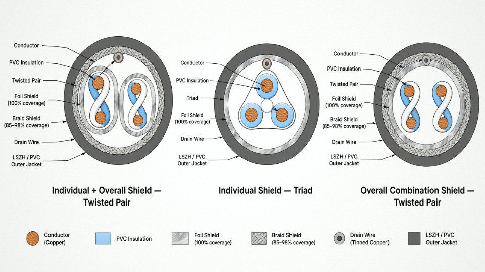
Instrumentation cables are constructed as twisted pairs (two conductors) or triads (three conductors — useful for three-wire RTD circuits or redundant loops). Twisting reduces magnetically induced interference by ensuring both conductors see nearly identical noise pickup, which then cancels at the differential receiver.
Shielding is where specifications get specific fast. The main options are:
- Individual shielding — each pair or triad has its own foil or braid shield, preventing crosstalk between loops within the same cable
- Overall shielding — a single shield wrapping the entire cable, mainly for external EMI rejection
- Combination (individual + overall) — the standard in high-noise environments like oil and gas or power stations
Shield coverage percentage matters. A foil shield gives close to 100% coverage but is fragile at terminations. A braid shield typically achieves 85–98% coverage depending on weave density — and that gap matters in genuinely hostile EMI environments. Combination shields with foil plus braid are worth the cost premium on any DCS or SCADA loop running within 300 mm of variable-frequency drives or high-voltage switchgear.
Where These Cables Actually Live
Oil and gas DCS field wiring, power station turbine control loops, water and wastewater SCADA installations, and pharmaceutical clean-room automation are the primary domains. Pharmaceutical environments add a layer of complication: halogen-free jacket materials are often mandated because combustion byproducts matter in occupied, enclosed spaces. The same logic applies to offshore platforms and tunnels.
Flame Retardancy Grades and When Each Is Required
IEC 60332 and related project standards define several grades that routinely appear in specs:
| Grade | Standard Basis | Typical Mandate |
|---|---|---|
| FR (Flame Retardant) | IEC 60332-1 | General industrial — single cable, vertical burn |
| FRT (Flame Retardant, Tray) | IEC 60332-3 | Cable trays, bundled runs |
| FRLS (FR, Low Smoke) | IEC 60332-3 + smoke density | Occupied buildings, tunnels |
| LSZH (Low Smoke Zero Halogen) | IEC 60754-1/2 | Offshore, rail, pharma, data centers |
Specifying FR when the project requires LSZH is a common procurement error — usually caught at factory acceptance testing, occasionally not caught until installation is complete.
Practical Ordering Checklist
When you send an inquiry for instrumentation cable, these are the parameters that actually define the product:
- Number of pairs or triads per cable
- Conductor cross-section (commonly 0.5 mm² or 1.0 mm²) and conductor class per IEC 60228
- Shield type — individual only, overall only, or combination; foil or braid; coverage percentage
- Drain wire required (yes/no, cross-section)
- Jacket material — PVC, LSZH, polyurethane for flexible or robotic applications
- Temperature rating — standard −20 °C to +70 °C covers most indoor plants; offshore or desert installations may need −40 °C or +90 °C ratings
- Required approvals — ATEX/IECEx for hazardous areas, UL/CSA for North American projects, DNV or Lloyd’s for marine
- Minimum bend radius and, for moving applications, flex-cycle rating
Shield coverage percentage in instrumentation cable directly affects signal-to-noise ratio in industrial EMI environments, with combination foil-plus-braid shields outperforming single-layer foil in high-noise installations.True
Electromagnetic shielding effectiveness depends on both coverage continuity and the shield's ability to reflect and absorb incident fields. Foil provides near-100% coverage but limited absorption; braid adds conductivity and some depth. In environments with VFDs and high-current cables nearby, combination shields measurably reduce induced noise on millivolt-level analog circuits, a principle consistent with IEC and IEEE shielding guidance.
Getting this list right before the order is placed, not during installation, is the difference between a clean commissioning and a noise-hunting exercise that can run weeks on a large process plant.
Data and Communication Cables: Structured Cabling, Fiber Optic, and Industrial Ethernet
Data cabling is probably the fastest-moving segment of the entire cable industry right now — driven by hyperscale data centers, 5G rollout, and the relentless push toward Industry 4.0 on factory floors. Getting the selection wrong doesn’t usually cause a fire. It causes something slower and more expensive: intermittent packet loss, EMI-induced data corruption, a structured cabling plant that needs ripping out and redoing in five years because the specification couldn’t keep up.
Category Copper Twisted-Pair Cables
Cat5e handles up to 1 Gbps at frequencies to 100 MHz and remains the baseline for basic office networks, though you’d be hard-pressed to justify specifying it new today. Cat6 pushes to 250 MHz and supports 10GBASE-T over short runs — up to roughly 55 m, depending on the alien crosstalk environment, which is the part the spec sheets always underplay. Cat6A extends that 10 Gbps capability to the full 100 m channel at 500 MHz; it’s noticeably thicker and stiffer than Cat6, which matters in dense tray runs. The physical difference is real: Cat6A augmented cables run 7–8 mm in diameter versus 5–6 mm for Cat6, and that chews through conduit fill capacity faster than engineers expect when they’re doing tray layouts.
Cat7 and Cat7A use individually shielded pairs plus an overall braid (S/FTP construction), targeting 600 MHz and 1,000 MHz respectively. They’re not officially recognized by TIA/EIA standards, which creates procurement headaches in North American projects. Cat8 is where structured cabling gets genuinely aggressive — rated to 2,000 MHz for 40GBASE-T or 25GBASE-T, but limited to 30 m, so it’s essentially a data-center top-of-rack cable, not a building backbone solution.
Coaxial Cables: Impedance and Attenuation Matter More Than the RG Number
The 50 Ω versus 75 Ω split is not arbitrary. RF transmission and instrumentation systems use 50 Ω (RG-58, RG-213) because that impedance minimizes power loss from the source — test equipment, antennas, industrial RF readers. CATV distribution and CCTV systems use 75 Ω (RG-6, RG-11) because that impedance minimizes signal attenuation over the long passive cable runs typical in those networks. Mixing them in a system introduces a standing-wave ratio mismatch that degrades signal; it’s a surprisingly common site error.
RG-6 at ~18 AWG handles residential and commercial CCTV and CATV fine up to a few hundred meters. RG-11 has a larger center conductor (roughly 14 AWG), lower attenuation per unit length — typically 30–40% less than RG-6 at 1 GHz — and is the right choice for long trunk runs or aerial distribution spans where RG-6 would require amplifiers.
RG-58 coaxial cable is suitable for modern CATV distribution networksFalse
RG-58 is a 50 Ω cable optimized for RF and instrumentation applications. CATV systems require 75 Ω impedance; using RG-58 introduces impedance mismatch and signal loss.
Fiber Optic: Construction Type and Fiber Class Are Separate Decisions
Single-mode fiber (OS2) carries one light path per strand, uses a 9 µm core, and delivers attenuation of roughly 0.2–0.4 dB/km at 1,310 nm — the actual figure depends on splice quality, bend radius compliance, and connector cleanliness far more than the cable itself. It’s the backbone of long-haul and campus-scale runs. Multi-mode fiber (OM3, OM4, OM5) uses a 50 µm core and supports shorter data-center links at lower transceiver cost. OM3 handles 10 Gbps to about 300 m; OM4 extends that to roughly 400 m; OM5 adds wideband support for shortwave-division multiplexing, relevant for emerging 100G+ data-center interconnects.
Construction choice — tight-buffered versus loose-tube — often gets decided by the installation environment rather than the fiber class. Loose-tube designs with gel filling handle outdoor direct-burial and duct runs well; the gel is messy to terminate but the design genuinely tolerates temperature swings and moisture ingress better than tight-buffered. Tight-buffered cables are cleaner to work with indoors and terminate directly onto connectors without a breakout kit. In practice, most large plants end up with both, which means the termination crew needs to know the difference.
Industrial Ethernet Cables: Rugged Is a Specification, Not a Marketing Word
Standard Cat6A won’t survive a welding shop floor for long. Industrial Ethernet cables — conforming to PROFINET, EtherNet/IP, or similar fieldbus physical-layer requirements — add real protection: TPE or PUR outer jackets instead of PVC, continuous flex ratings often in the range of 5–10 million bending cycles (versus essentially zero for standard structured cabling), and resistance to cutting oils, coolant splash, and UV. Connector compatibility with M12 D-coded or X-coded field-installable connectors rated to IP67 or IP68 is non-negotiable in wet-process or washdown environments.
The flex-life rating depends heavily on bend radius relative to cable diameter — a spec often buried in the datasheet that procurement teams skip. Getting it wrong means cable jackets crack within a year on a robot arm or a cable carrier.
Hybrid Cables: One Pull, Two Functions
Wind turbine nacelles, smart streetlight poles, and traffic-monitoring masts increasingly need power delivery and high-bandwidth data in the same conduit. Hybrid cables combine, in a single sheath, power conductors (typically 1.5–6 mm²), fiber strands (usually 2–12 fibers), and sometimes a copper data pair. The value is operational: one cable pull, one conduit, one set of sealing glands. The challenge is that the power and fiber components have very different minimum bend radius requirements, and the cable manufacturer has to engineer the stranding geometry to satisfy both simultaneously. Specifying a hybrid cable from a manufacturer who just bundles conductors together without that geometric engineering is a reliable way to end up with broken fibers at installation.
For smart city infrastructure specifically, the hybrid cable approach is pushing into mainstream procurement. The market is growing, though it remains a small fraction of total cable volume — the demand is real but concentrated in specific verticals rather than broadly distributed.
Specialty Industrial Cables: Mining, Oil and Gas, Offshore, and Trailing Flex Designs
Standard power or control cables simply aren’t built for environments where a mechanical strike, a hydrocarbon spill, or a methane ignition isn’t a theoretical risk — it’s a Tuesday. Specialty industrial cables occupy a smaller slice of total cable volume but a disproportionately large share of project cost and liability. Getting the specification wrong here doesn’t mean a tripped breaker. It means an explosion hazard, a flooded umbilical, or a reeling cable that fatigues and fails after 50,000 cycles instead of the 500,000 the operation demands.
Mining Cables and the Anti-Static Requirement
Underground mining cables take more physical punishment per meter than almost any other installation. The insulation and sheath compound matters enormously here — CPE (chlorinated polyethylene) and HOFR (heat, oil, and flame retardant) rubber are both widely used, and which one gets specified usually comes down to ambient temperature range, the presence of hydraulic fluids, and what the mine operator’s maintenance crew is already familiar with. Steel wire armor provides the mechanical protection layer, typically applied over a bedding compound to prevent wire migration under repeated flexing.
The detail that trips up procurement teams new to mining projects: anti-static jacket compounds are not optional in methane-risk zones. IEC 60502 covers general construction requirements, but BS 6708 — the British standard specifically addressing flexible cables for use in mines — goes further on surface resistivity limits for jacket materials. Exceeding those resistivity limits in a gassy heading creates a static discharge ignition path. This isn’t an edge-case concern.
Oil and Gas: Mud Resistance, Fire Performance, and Subsea Umbilicals
Topside oil and gas installations demand cables that shrug off hydrocarbon contamination, resist aggressive cleaning chemicals, and maintain circuit integrity under fire long enough for safe evacuation. FP (fire-resistant/fire-proof) cable designs to IEC 60331 are the baseline for safety-critical circuits on platforms — the standard requires the cable to maintain electrical function at 750–850 °C for at least 90 minutes, depending on the test category.
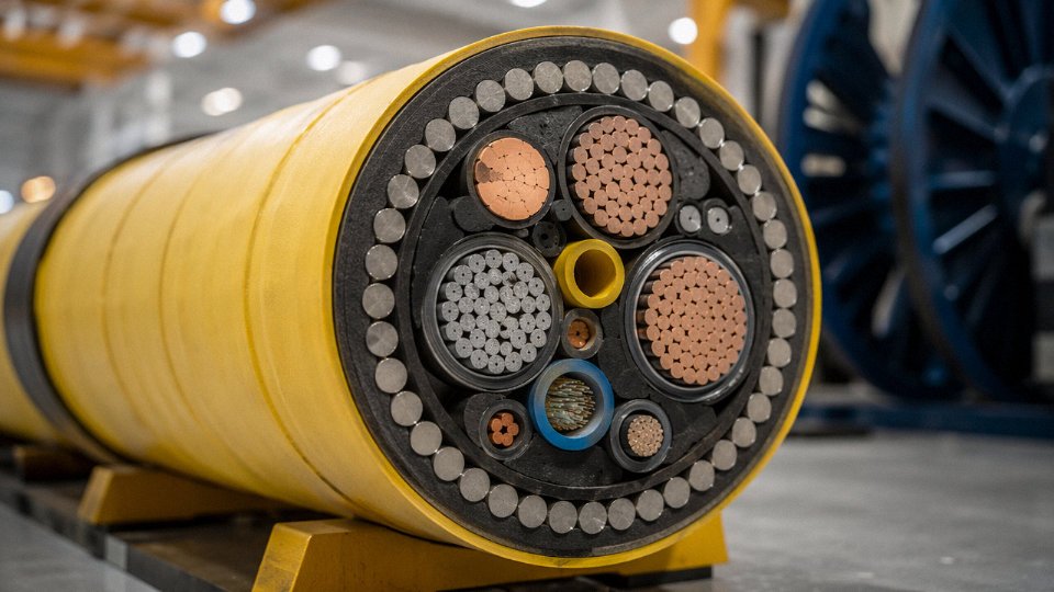
Subsea umbilicals are a different animal entirely. A typical production umbilical bundles power conductors, hydraulic hoses, chemical injection lines, and signal conductors into a single helically-laid assembly that may need to survive 20–30 years of continuous dynamic loading on the seabed or in a lazy-wave riser configuration. The mud-resistant outer sheath — usually a high-density polyethylene compound or polyurethane — gets specified against specific drilling fluid chemistries, not just “mud” generically. Procurement teams should request immersion test data against the actual fluid formulation used on that field.
Trailing and Reeling Cables for Mobile Equipment
Port cranes, dragline excavators, mining shovels, and tunnel boring machines all share one cable problem: the cable moves constantly. Trailing and reeling cables fail by fatigue, not by insulation degradation, so conductor strand count is the first specification to check. Class 5 and Class 6 flexible conductors per IEC 60228 are the standard choices — Class 6 (the finer stranding) is used where the drum diameter is small or the cycling rate is high. The insulation compound also needs helical memory — the ability to return to its original geometry after repeated bending — otherwise the insulation cracks at the bend point within a few thousand cycles.
Minimum bend radius is a contractual number, not a suggestion. For a typical 95 mm² trailing cable on a bucket-wheel excavator, that radius might be 8–10 times the cable OD. Specify it, mark it on the drum housing, and train the maintenance crew.
Offshore and Marine: Classification Society Approvals
Marine cable specifications layer environmental performance onto everything else. UV stability matters on deck. Seawater immersion resistance matters in cable transits and bilge areas. In confined vessel spaces — accommodation modules, engine rooms — low-toxicity smoke emission under IEC 60092 and flame retardancy per IEC 60332-3 matter for survivability during a fire event.
DNV, Lloyd’s Register, and ABS each maintain type-approval schemes that require witnessed testing and factory audits, not just self-declaration. An EPC contractor specifying cables for an FPSO or a navy vessel will generally not accept a cable that isn’t on an active approval list, regardless of how the datasheet reads.
Jinda produces SHF1 and SHF2 rubber-sheathed ship cables with third-party certification support from recognized classification bodies.True
SHF1 and SHF2 are IEC 60092-defined sheath compound designations for shipboard cables; Jinda's production capability for these products and its provision of third-party certification documentation is consistent with its stated manufacturing scope and international project supply track record.
Jinda’s SHF1 and SHF2 rubber-sheathed ship cables are built against IEC 60092 series requirements, with documentation packages structured to satisfy EPC contractor submission requirements — type approval certificates, factory test reports, and third-party inspection coordination. For international projects where the certifying body matters as much as the cable spec itself, that documentation trail is what moves a cable supplier from the “possible” column to the “approved” column.
Building Wiring, Fire-Resistant, and Low-Smoke Zero-Halogen Cables for Safe Construction Projects
Most procurement disputes in construction cabling don’t start with the high-voltage stuff — they start with the basic building wire spec, usually because someone swapped a compliant type for a cheaper local alternative mid-project. That substitution rarely shows up until an inspection, a fire-damage claim, or a failed test certificate review.
Standard Building Wire: THHN, NM-B, NYY, and NYYJ
THHN is the workhorse of North American conduit wiring — 90°C rated, PVC insulated with a nylon jacket, available from roughly 14 AWG up to 1,000 kcmil. It is always installed in conduit or raceway; never direct-burial, never exposed in open-air wet locations without additional protection. NEC Article 310 governs ampacity, and the derating tables there are worth memorizing if you’re specifying multi-conductor bundles in conduit, because crowding drops your effective current capacity faster than most junior engineers expect.
NM-B (the generic name for what most people call Romex-style cable) is a non-metallic sheathed cable for dry, concealed residential and light commercial in-wall runs. Convenient for residential builds. Completely wrong for commercial conduit work, industrial environments, or anywhere with mechanical abuse risk.
In IEC-aligned markets, NYY and NYYJ are the corresponding reference types — PVC-insulated, PVC-sheathed, 0.6/1 kV rated, suitable for direct-burial (NYY) or conduit installation. Conductor sizing follows IEC 60228, running from 1.5 mm² residential circuits up to 240 mm² or beyond for distribution feeders. The “J” designation in NYYJ simply indicates an additional green/yellow protective earth conductor — a detail that trips up procurement teams sourcing across European and Asian suppliers who label things differently.
Fire-Resistant Cables: Circuit Integrity When It Counts Most
Fire-resistant cables — designated FP or CWZ depending on the regional standard — are built around a fundamentally different logic than standard building wire. The key construction feature is mica tape wrapping applied directly over each conductor before the insulation layer is added. Mica stays rigid and electrically insulating even as surrounding materials burn away, which is how these cables can maintain circuit integrity at temperatures between 850°C and 1,000°C for 90 to 120 minutes depending on the construction grade.
That runtime matters enormously. Emergency lighting circuits, fire pump feeders, elevator recall wiring, PA and alarm systems — all of these need to keep functioning long enough for evacuation and suppression to do their job. Using a standard PVC cable in those circuits isn’t just a code violation; it’s a design failure with a predictable outcome.
EN 50200 and BS 8491 are the primary test standards for fire-resistant performance. EN 50200 covers cables up to 20 mm overall diameter under a 30-minute mechanical shock sequence combined with flame exposure. BS 8491 extends this to larger cables and adds water spray during the fire test — closer to real suppression conditions. Specifiers working on hospitals, high-rise residential, or transport hubs should be confirming which test applies before they accept a cable sample.
Mica tape insulation in fire-resistant cables maintains electrical circuit continuity at temperatures up to 1,000°C for a minimum of 90 minutes under IEC/EN test conditions.True
This is consistent with EN 50200 and BS 8491 test protocols, where mica-taped conductor constructions are specifically evaluated for circuit integrity under sustained flame and mechanical stress exposure.
LSZH Cables: Toxicity and Smoke Density in Confined Spaces
Low Smoke Zero Halogen — LSZH, or sometimes LSHF or LS0H depending on who’s writing the spec — addresses a different failure mode than heat or flame spread. Standard PVC insulation, when it burns, releases hydrogen chloride gas. In a tunnel, underground station, or hospital corridor, that gas is what kills people who aren’t directly in the fire.
LSZH compounds are halogen-free, formulated typically from EVA, polyolefin blends, or similar materials, and must produce less than 0.5% hydrogen chloride emission by weight under IEC 60754-1 testing. Smoke density is measured separately under IEC 61034, which tests light transmittance through combustion gases — values above 60% transmittance are required for compliant cable. Both figures matter. A cable can pass the HCl test and still produce a dense black smoke cloud that makes evacuation impossible.
For IEC 60332 flame propagation testing: -1 tests a single cable vertically, -3 covers bunched cable installations in trays, and the -3 variants (A, B, C, D) correspond to increasing volumes of non-metallic material per meter. Bunched-cable flame propagation in a tray is genuinely worse than a single cable scenario, which is why specifying only IEC 60332-1 compliance for a cable tray installation is technically inadequate.
CPR Euroclasses and the DoP Requirement in European Projects
Since 2016, cables installed in buildings within the EU must comply with the Construction Products Regulation (CPR), which introduced a Euroclass flame performance ladder running from Aca (best) through B1ca, B2ca, Cca, Dca, Eca, down to Fca (no performance determined). Each class also carries sub-classifications for smoke (s1/s2/s3), flaming droplets (d0/d1/d2), and acidity (a1/a2/a3).
In practice, most commercial building wiring lands at Cca or Dca. Data center cabling increasingly targets B2ca-s1,d0,a1 for the combined low smoke and acidity performance. Aca is typically mineral-insulated cable territory.
The DoP — Declaration of Performance — is the manufacturer’s legally binding document stating which Euroclass has been achieved under which notified body testing. Procurement teams sourcing cable for EU projects should be requesting the DoP before order confirmation, not after delivery. Auditors will ask for it. Some contractors find this out at practical completion, which is a very expensive time to discover you accepted non-compliant material.
Renewable Energy Cables: Solar PV, Wind Power, and EV Charging Infrastructure
The energy transition has done something the cable industry hasn’t seen in decades: it’s created entirely new cable categories rather than just incremental updates to existing ones. Solar DC cables, torsion-resistant wind turbine leads, liquid-cooled EV charging cables — none of these existed in meaningful commercial volumes fifteen years ago. Now they’re among the fastest-growing line items in procurement budgets worldwide.
Solar PV DC Cables: Built for a Harsher Environment Than Most Engineers Expect
Rooftop and utility-scale solar installations expose cables to conditions that would degrade standard building wire within a few seasons. Prolonged UV exposure, ozone, thermal cycling from −40°C to +90°C daily, and in many climates, direct soil contact or roof membrane contact — the cable has to survive all of it, unattended, for the 25–30 year project life of the array.
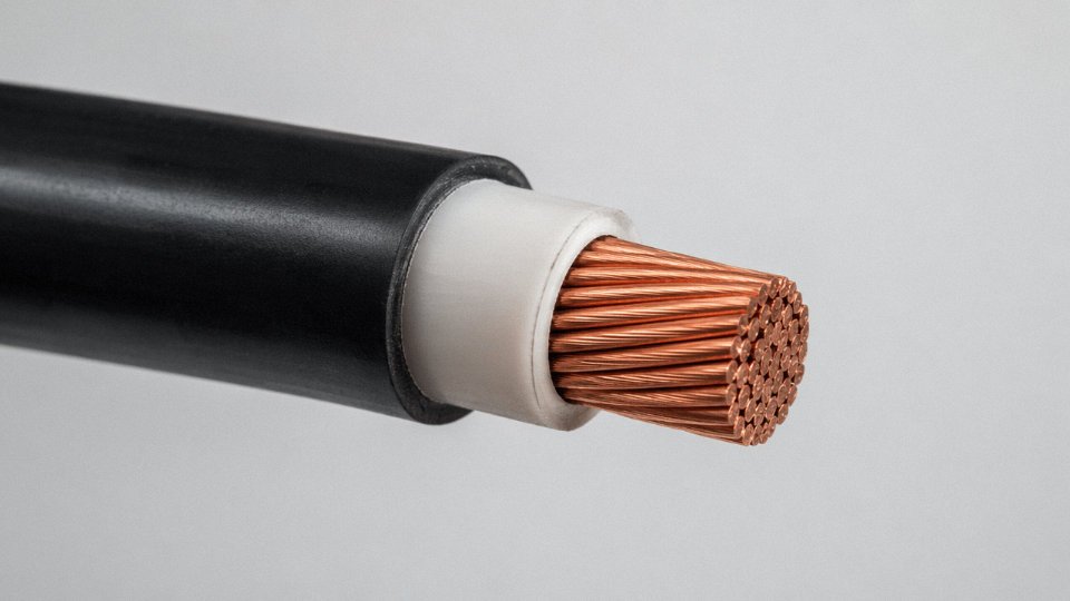
The governing specifications are TÜV 2Pfg 1169 and EN 50618, and if you’re buying PV cable for a project going into Europe or a European-financed site anywhere in the world, compliance with one or both isn’t optional. Both standards require cross-linked polymer insulation and sheathing — typically XLPE or EPR-based compounds — precisely because conventional PVC softens and migrates under sustained heat and loses mechanical integrity when ozone attacks it. The dual-insulation (double-jacketed) construction addresses double-fault protection: if the outer sheath is breached, the inner insulation still maintains isolation, which matters in a DC system where arc faults don’t self-extinguish the way AC faults sometimes do.
Voltage ratings sit at 1.5 kV DC for most residential and commercial strings, moving to 1.8 kV DC for utility-scale systems using higher-voltage string inverters. Don’t underspec this; a 1 kV-rated general-purpose cable in a 1.5 kV DC string is a fire waiting to happen.
Wind Farm Cables: Two Very Different Problems in One Turbine
Offshore wind inter-array cables — the submarine cables linking turbine foundations back to the offshore substation — typically operate at 33 kV, with newer large-array projects pushing to 66 kV to reduce current and therefore conductor losses across long inter-turbine spans. These are essentially a variant of medium-voltage submarine power cable, with water-blocking layers, armoring suited to the seabed installation method (whether plowed, trenched, or j-tube laid), and bend stiffeners at the transition zones.
The cables inside the tower are a different challenge entirely. As the nacelle yaws — rotating to track wind direction — the cables running up through the tower twist and untwist repeatedly. Over a 20-year service life, a turbine in a variable-wind site can accumulate millions of torsion cycles. Standard power cable construction fails under this; the conductors work-harden and eventually fracture. Torsion-resistant designs use flexible stranded conductors (typically IEC 60228 Class 5 or Class 6), helically laid cores with controlled lay length, and elastomeric sheaths that accommodate repeated mechanical deformation without cracking. Specifying the wrong cable for the tower interior is one of those mistakes that doesn’t show up until year four or five, and by then you’re doing a tower climb to replace it.
EV Charging Cables: Mode Matters More Than People Realize
Mode 2, Mode 3, and Mode 4 cables are not interchangeable, and the construction differences are substantial.
Mode 2 — the occasional-use cable supplied with the vehicle — is a relatively simple flexible cord with an in-cable control box (ICCB). It’s adequate for occasional top-up charging but not for sustained daily use in a commercial setting.
Mode 3 cables connect to dedicated AC charging stations (wallboxes, public AC points) under IEC 61851 and IEC 62196. The cable carries pilot and proximity signals alongside the power conductors, and the sheath compound needs to handle outdoor exposure plus repeated coiling and uncoiling — a detail that cheap sourcing tends to compromise first.
Mode 4 is DC fast charging, and the cable construction here is genuinely demanding. At 150–350 kW charging power, the current through the cable generates heat that a passively cooled cable can only manage by using very large conductors, which makes the cable heavy and stiff. The practical solution for 350 kW ultra-fast chargers is liquid-cooled cable: a small-diameter coolant circuit runs inside the cable assembly, pulling heat out of the conductors continuously. This lets the cable remain flexible and manageable for the driver while handling currents that would require a 95 mm² or larger conductor in a passive design. Standards covering EV charging include IEC 62196, IEC 61851, and GB/T 20234 for the Chinese market — procurement teams sourcing for multi-country rollouts need to confirm which standard governs each territory before finalizing specs.
The IEA projects global EV stock will reach 250 million vehicles by 2030, requiring an estimated 40 million public charging points.True
This projection is consistent with the IEA's Global EV Outlook reports, which model charging infrastructure requirements against fleet growth scenarios under stated-policies and announced-pledges cases.
Each of those 40 million charging points requires roughly 15–100 meters of charging cable depending on installation type, parking geometry, and whether the cable is permanently fixed or user-handled. That’s a cable demand figure measured in billions of meters over the decade.
BESS Interconnect Cables: Short Runs, Serious Thermal Requirements
Battery energy storage systems don’t get much attention in cable discussions, but the interconnect cables inside battery enclosures are a legitimate specification challenge. The runs are short — often under a meter between modules — but current levels are high, ambient temperatures inside enclosures can sit at 40–50°C continuously, and the insulation has to remain dimensionally stable and electrically sound across thousands of charge-discharge cycles without any possibility of maintenance access.
Flexible welding-type cables and laminated busbar assemblies are both used here. The key insulation requirement is thermal stability: standard PVC-insulated cables rated at 70°C conductor temperature have almost no margin in a hot battery enclosure. XLPE or silicone insulation, rated at 90°C or 105°C, is the more defensible choice. Flame-retardant and low-smoke properties matter too — a thermal runaway event in a BESS enclosure is already a serious incident; cable combustion products shouldn’t accelerate it.
How to Read a Cable Designation Code and Decode Manufacturer Datasheets
A surprising number of procurement errors happen not because the buyer chose the wrong cable type, but because they misread the designation string on the datasheet or, worse, assumed two cables with similar-sounding names were interchangeable. Getting fluent in cable coding conventions saves real money — wrong armor specification on a direct-buried run, for instance, means excavating and re-pulling.
Decoding an IEC-Style Designation
Take a typical IEC designation: 3×95+1×50 mm² XLPE/SWA/PVC 0.6/1 kV.
Each element is a distinct decision:
- 3×95 — three main conductors, each 95 mm² cross-section. These carry phase current.
- +1×50 — one additional conductor at 50 mm², typically the neutral or earth, deliberately undersized relative to the phases (common in three-phase systems where the neutral carries reduced unbalanced load).
- XLPE — cross-linked polyethylene insulation. Not interchangeable with standard PE or PVC; XLPE handles sustained conductor temperatures up to roughly 90°C and offers better performance under cyclic overload.
- SWA — steel wire armor. Gives radial crush resistance and tensile strength for direct burial or cable tray without additional mechanical protection. Swap this to AWA (aluminum wire armor) if you’re running on aluminum raceways or need to reduce weight on an offshore topsides installation.
- PVC — outer sheath material. On projects in tunnels or building risers, you’d specify LSZH or LSHF here instead.
- 0.6/1 kV — rated voltage. The first figure (0.6 kV) is conductor-to-earth; the second (1 kV) is conductor-to-conductor. Applying a 0.6/1 kV cable on a 1.1 kV system is outside design intent even if it “only” runs at 1 kV phase-to-phase — insulation coordination matters.
North American Coding Logic Is Structurally Different
IEC names describe construction. North American codes largely describe environment and temperature rating. XHHW-2, for example, tells you: X = XLPE insulation, HH = rated for 90°C dry and wet, W = suitable for wet locations, -2 = meets specific UL 44 requirements for wet 90°C. What it does not tell you directly is conductor cross-section format, armor class, or sheath material — those appear separately on the datasheet or in the conduit-fill schedule.
THWN is thermoplastic (T), heat-resistant to 75°C (H), wet-rated (W), nylon-jacketed (N). USE-2 is underground service entrance cable rated for 90°C wet — common in solar PV string wiring in North American installations, though it’s increasingly being displaced by PV-rated USE-2/RHH/RHW-2 dual-rated conductors.
Projects that mix IEC-designed equipment with NEC-governed site wiring need a deliberate interface plan. Voltage rating conventions differ; conductor sizing tables differ (mm² versus AWG/kcmil); derating table structures differ. Assuming equivalence without cross-referencing is where problems quietly accumulate.
Datasheet Parameters That Actually Matter
Most datasheets include more numbers than any one project needs. The ones worth verifying every time:
| Parameter | Why It Matters | Common Oversight |
|---|---|---|
| DC resistance at 20°C (Ω/km) | Voltage drop and losses | Ignoring temperature correction to actual operating temp |
| Current-carrying capacity — in air vs. buried | Different by 15–30% depending on installation | Using in-air rating for buried runs |
| Short-circuit current rating (kA, 1s) | Fault protection coordination | Undersized on long LV feeders |
| Capacitance per phase (nF/km) | Charging current on HV cables, especially long runs | Often ignored below 33 kV, matters at 66 kV+ |
| Inductance (mH/km) | Reactive voltage drop on loaded circuits | Relevant on large-conductor long feeders |
For cables above roughly 33 kV, charging current can be 5–15% of thermal rating on runs over a few kilometers — ignore it and your protection relay settings will be wrong.
Ambient temperature derating is where I see the most consistent errors in procurement specifications. Standard current ratings assume 30°C ambient in air and a soil thermal resistivity of around 1.0 K·m/W for buried cables. In practice, a cable routed in a 45°C boiler room needs a derating factor somewhere in the range of 0.84–0.87 (exact value depends on insulation class and the specific table in IEC 60364-5-52 or IEC 60502). Bundle four loaded cables in a single conduit and you’re stacking another factor of roughly 0.65–0.75 on top. These multiply — so a cable rated at 200 A in free air might be limited to around 120–130 A in that conduit inside that hot room. Size for the worst credible condition, not the nominal one.
Standard IEC current-carrying capacity tables assume 30°C ambient air temperature and soil thermal resistivity of 1.0 K·m/W; higher ambient or soil resistivity requires explicit derating per IEC 60364-5-52.True
This is defined in IEC 60364-5-52 and IEC 60502-1 installation guidance. Both ambient temperature correction factors and soil thermal resistivity corrections are tabulated, and values are not interchangeable between installation methods.
Reading Test Certificates Without Being Fooled
A datasheet with a CE mark or a self-declared test summary is not the same as a cable with witnessed third-party type test reports. Per IEC 60502, there are three test tiers: routine tests (done on every drum — insulation resistance, high-voltage withstand), type tests (done on a representative sample to qualify the design — bending, impact, fire propagation, aging), and special tests (project-specific, agreed contractually).
When ordering anything above low-voltage commodity cable, ask explicitly for the type test reports — not just a certificate number. KEMA (Netherlands), CESI (Italy), SGS, and similar accredited bodies issue reports with test dates and sample descriptions. A reputable manufacturer can produce these without hesitation. If the response is a glossy one-page certificate with no underlying test data, treat that as a flag worth investigating before the order is placed.
CCC certification covers mandatory product categories for the Chinese domestic market. UL listing matters for North American jurisdictions. Neither automatically validates performance for a project governed by IEC standards — they address different test regimes, and conflating them is a procurement risk that shows up at commissioning when the insurance or EPC contractor’s engineer starts asking questions.
Frequently Asked Questions About Cable Types, Selection, and Global Procurement
How many types of cables are there in total?
More than 20 broad cable families exist in commercial use, and once you start counting construction variants — conductor class, insulation material, armoring style, sheath compound, voltage grade, temperature rating — the sub-type count runs well into the hundreds. IEC alone publishes dozens of product standards covering everything from 300/500 V flexible cords to 500 kV XLPE transmission cables. In practice, most engineers spend their careers working with maybe 8–12 of those families regularly. This article covers the categories that actually drive procurement volume and project decisions: power, control, instrumentation, data, fire-rated, specialty industrial, and renewable energy cables.
What is the difference between a cable and a wire?
Straightforward in principle, occasionally blurred on datasheets. A wire is a single conductor — either solid or stranded — that may or may not carry a thin insulating layer. A cable is an assembly: two or more insulated conductors laid up together, or even a single insulated conductor that has been given a protective outer sheath, screen, or armor. So a single 35 mm² XLPE-insulated, SWA-armored conductor in a PVC outer jacket is technically a cable even though it carries one circuit. The distinction matters on a purchase order because “wire” and “cable” can fall under different test regimes, certifications, and installation codes.
Which cable type is best for outdoor direct burial?
For direct burial, XLPE-insulated armored cable is the standard choice in most markets. Steel wire armored (SWA) construction suits three-core and multi-core runs; aluminum wire armored (AWA) is preferred for single-core AC circuits because steel armor on single-core cables creates problematic eddy-current heating. The outer jacket — PVC or HDPE depending on soil chemistry and thermal requirements — should be UV-stabilized if any portion of the run is above grade, even a short section at a termination point. Look for compliance with IEC 60502-1 (up to and including 1 kV) or IEC 60502-2 (3.6/6 kV through 20.8/36 kV). Also confirm the minimum bending radius spec before laying — cold weather installation with stiff PE sheaths catches people out more often than it should.
XLPE-insulated underground cables, when correctly installed, can achieve a service life exceeding 40 years.True
This is consistent with IEC design life data and long-term field performance records for properly installed XLPE MV and HV cables in stable soil conditions.
How do I verify a Chinese cable manufacturer’s quality before placing a bulk order?
Start with documentation. Request full IEC type test reports issued by an accredited third-party lab — SGS, Bureau Veritas, CESI, and KEMA are the names buyers in Europe and the Middle East recognize and trust. Review the CCC (China Compulsory Certification) scope carefully; a certificate covering one product range does not automatically cover every variant you’re ordering. Where the order value justifies it, a third-party factory audit before production is worth the cost — not a courtesy visit, an actual audit with process checks and raw material traceability review. For each delivered drum, ask for production test records covering at minimum conductor DC resistance and high-voltage withstand test results. Reputable manufacturers generate these routinely and can supply them per reel. If a supplier hesitates on that last point, that’s information.
What is LSZH cable and when is it required?
LSZH stands for Low Smoke Zero Halogen. The insulation and sheath compounds contain no chlorine, fluorine, or bromine, so when the cable burns it releases minimal smoke and produces no hydrogen chloride or other toxic halogen gases. That matters enormously in confined spaces — metro tunnels, airport terminals, hospital corridors, offshore accommodation modules — where burning PVC can incapacitate people and make evacuation genuinely dangerous before any structural fire damage occurs. Many building codes and project specifications now mandate LSZH in those environments. It costs more than standard PVC cable, roughly 15–35% more depending on conductor cross-section and market conditions, so substituting it across an entire facility without checking the actual requirement zone-by-zone is a procurement mistake that shows up on the budget.
Can one manufacturer supply multiple cable types for a large-scale project?
Yes, and there are real logistics and quality-management advantages when they can. A single-source supplier for LV power, MV power, control, instrumentation, fire-resistant, and specialty cables means consolidated shipping, a single set of quality documentation, and one point of accountability when something is wrong. For Jinda, with multiple production lines across five manufacturing bases, covering that full range for an EPC contractor or utility-scale project is routine — not a special arrangement. In practice, multi-cable projects often use one primary supplier for 70–80% of the cable schedule and a secondary source for a handful of highly specialized items nobody stocks in volume. That’s a reasonable approach as long as both suppliers are fully qualified before production begins, not after the first delivery lands on site.
Partnering With a Global Cable Manufacturer: What to Expect From Jinda’s Supply Chain
Sourcing cables internationally sounds straightforward until you’re three weeks from a commissioning deadline and the drums that arrived have inconsistent insulation wall thickness, no per-drum test certificates, and drum sizes that ate 30% of your container space with air. That scenario is more common than most procurement managers admit. The difference usually comes down to whether the manufacturer actually controls its own process or is assembling product from subcontracted components and hoping for the best.
Jinda has operated since 1987, which means the production and quality systems have been stress-tested across enough market cycles, customer audits, and project failures to develop into something real rather than cosmetic.
Production Bases and What Each One Actually Does
Five manufacturing bases across China, covering roughly 470,000 m² total, is not a brochure claim — it reflects a deliberate decision to keep product families on dedicated lines rather than running everything through one shared facility. Low- and medium-voltage power cables (XLPE and PVC insulated, up to 35 kV) run on lines sized for continuous high-volume output, with stranding and extrusion equipment matched to the conductor cross-section range IEC 60228 specifies from 0.5 mm² up through the larger power cable sizes. Specialty rubber cables — trailing flex designs for mining equipment, submersible pump cables, highly flexible welding cable — get their own facility because the compound mixing tolerances and vulcanization parameters genuinely cannot share a production schedule with PVC extrusion without quality compromises. Fire-resistant and LSZH cables require dedicated compound handling and separate extrusion lines to prevent halogen contamination of nominally halogen-free material; running them on shared equipment is a recurring audit finding at lower-tier manufacturers. High-voltage cables up to 110 kV demand a clean-room extrusion environment, triple-layer co-extrusion for conductor screen, insulation, and insulation screen in a single pass, and post-extrusion degassing time that cannot be rushed without affecting partial discharge performance. Keeping that on its own line protects delivery reliability for the rest of the product range too.
Quality Assurance: Where It Actually Starts
The traceability chain begins at copper rod. Heat number records from the rod supplier feed into in-house conductor drawing and stranding logs, so if a field issue ever surfaces years post-installation, you can pull the production batch record and trace back to raw material. Online eccentricity monitoring during extrusion catches wall thickness drift before it becomes a drum-level reject rather than a customer complaint. Every finished drum goes through 100% routine high-voltage withstand testing — not sampled, every drum — with test results documented per drum and available as part of the shipping package.
Jinda holds CCC, CE, and TÜV certification for PV cables, with type test reports covering IEC 60502, IEC 60228, IEC 60332, and EN 50618 from accredited independent laboratories.True
These are verifiable certifications and standards held by Jinda; procurement teams can and should request copies of type test reports and certificate numbers for independent verification before placing bulk orders.
For solar procurement teams specifically: TÜV certification on PV cable matters because the EN 50618 type test covers UV resistance, ozone resistance, and the thermal aging profile that determines whether a cable genuinely survives 25 years of rooftop exposure or just passes a room-temperature datasheet check.
Export Logistics Done Properly
Shipping to more than 50 countries creates real operational knowledge around container optimization. Drum outer diameters and drum lengths get calculated against 20-foot and 40-foot container internal dimensions so you’re not paying ocean freight on dead space. Documentation packages — Mill Test Certificate, packing list, per-drum test certificate, and any customer-specific formats — are prepared as standard, not as a special request that delays the shipment.
Starting a Procurement Conversation
For project work, Jinda’s technical team can review cable schedules during pre-qualification, flag specification gaps, and provide samples before bulk order commitment. Long-term supply agreements with dedicated account management are available for buyers who need price and lead-time stability across multiple project phases. Reach out through the contact page on jindacable.com to get a specific inquiry in front of the right product team.