Coaxial cable shows up in so many different installation contexts — satellite dishes, CCTV backbones, RF distribution, sometimes even repurposed in industrial sensing runs — that the voltage classification question comes up more than you’d expect. Get the answer wrong during design, and you’re looking at mismatched conduit fill rules, wrong gland selections, or a compliance inspector flagging your installation because the cable landed in the wrong segregation tray. That kind of rework mid-project is expensive and almost always avoidable.
Coaxial cable is generally considered low voltage under IEC 60038, since most types operate between 300 V RMS and 600 V RMS — well within the 50 V to 1,000 V AC threshold that defines low voltage. However, the actual classification depends on cable type, dielectric material, and application: some specialist coax designs can reach 5,000 V peak, which pushes them out of the standard low-voltage band entirely.
What makes this genuinely tricky is that “voltage rating” on a coax cable isn’t the same thing as “operating voltage in your system,” and the two get conflated constantly on the shop floor. The RG designation tells you something about construction and impedance, but the voltage classification question — the one that determines how your installation gets inspected and permitted — depends on which standard your jurisdiction is working from and exactly what the cable is carrying. That distinction matters more than most people realize.
Coaxial Cable Construction and How It Governs Voltage Rating
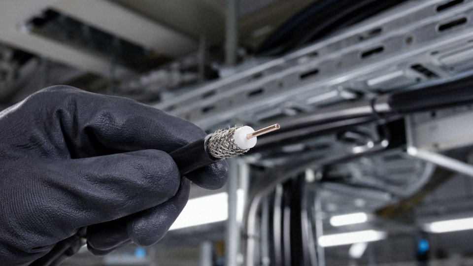
Understanding why a coaxial cable gets a specific voltage rating — and why that rating is often lower than the dielectric physics would theoretically allow — starts with a close look at what’s actually inside the cable. Each layer plays a distinct role, and they don’t all contribute equally to voltage withstand.
The Center Conductor
The innermost element is either solid or stranded copper, or copper-clad steel (CCS) for applications where tensile strength matters more than pure conductivity — aerial runs, for instance, or drop cables that get pulled through conduit repeatedly. For RF and signal use, this conductor carries the signal current. Its diameter, along with the dielectric geometry around it, sets the cable’s characteristic impedance. From a voltage standpoint, the center conductor itself isn’t the weak link. What matters is how well it’s centered within the dielectric, because an off-center conductor reduces the effective insulation thickness on one side and creates a localized high-field zone. On the production floor, this is a quality control issue, not a design one — and it’s one reason reputable manufacturers specify conductor concentricity as a hard tolerance.
The Dielectric: This Is Your Actual Voltage Barrier
The dielectric insulation — typically solid polyethylene (solid PE), foam PE, or PTFE in higher-frequency or high-temperature variants — is the primary voltage-withstanding layer in a coaxial cable. Full stop. Everything else is secondary.
Solid PE has a dielectric breakdown strength of roughly 18–23 kV/mm, depending on compound grade and extrusion quality. A standard RG-6 cable carries a dielectric wall thickness somewhere around 3–4 mm in the insulation zone, which gives a theoretical breakdown voltage well above 10,000 V. So why is RG-6 rated at 300 V RMS in working use?
RG-6 coaxial cable is rated at 300 V RMS despite its dielectric being physically capable of withstanding far higher voltages.True
The working voltage rating reflects a conservative derating that accounts for safety margins, long-term insulation aging, connector interface vulnerabilities, and the need to protect signal integrity — not the raw dielectric breakdown strength of the polyethylene insulation itself.
Two reasons drive that derating. First, the connector interfaces — where the dielectric is mechanically disturbed, trimmed, or compressed — are far weaker than the cable body itself. Second, signal integrity degrades before insulation fails. Partial discharge events at voltages well below breakdown can introduce noise, and in broadcast or CATV infrastructure, that’s a functional failure even if nothing melts. Foam PE, used in low-loss cables like quad-shield RG-6 variants, has slightly lower dielectric strength than solid PE because of its cellular structure, so those cables derate further in some constructions.
The Outer Conductor and Shield
The braided wire shield, foil layer, or combination of both serves as the return path for RF current and as an electromagnetic barrier. For voltage purposes, it functions as a Faraday cage that keeps the internal electric field contained. Its contribution to voltage withstand is indirect — it defines the outer boundary of the dielectric. A loose or poorly bonded shield increases effective dielectric geometry variability, which indirectly affects voltage performance under testing.
Outer Jacket
PVC, LSZH, or PE jackets protect against mechanical damage, UV, and moisture ingress. They’re not rated as primary insulation for working voltage purposes. Don’t let a thick outer jacket mislead a specifier into assuming higher voltage capability.
Impedance Is an RF Parameter, Not a Voltage Parameter
This distinction causes genuine confusion in procurement. A 50 Ω cable (the standard for data transmission, RF test equipment, and most industrial wireless infrastructure) and a 75 Ω cable (broadcast, CATV, satellite distribution) are designed around characteristic impedance — a function of conductor diameter, dielectric constant, and geometry. Impedance governs how efficiently a signal transfers between source and load at high frequencies. It has nothing to do with how much voltage the insulation can withstand.
Buyers comparing coaxial cable to standard power cable sometimes assume the 75 Ω broadcast cable is “heavier duty” because it’s physically larger. Usually it isn’t, in any voltage sense. An RG-11 cable rated to 600 V RMS is larger than RG-6 primarily because its geometry is optimized for lower signal attenuation over long runs, not because it’s designed to handle higher voltage loads. The two parameters live in completely separate engineering domains, and conflating them leads to misspecification — sometimes with real consequences at commissioning when an installer routes coax alongside power conductors and assumes the voltage ratings are equivalent to those of the power cable.
Voltage Ratings of Common Coaxial Cable Types: RG-6, RG-11, RG-58, LMR, and Trunk Cables
If you spec coax purely by impedance and loss figures — which most engineers do, at least initially — voltage rating tends to get treated as an afterthought. That’s usually fine for a home antenna install. It becomes a real problem on a telecom tower, a cable TV headend, or any industrial site where signal cables share conduit with power feeds.
The table below gives working voltage ratings alongside the parameters that actually matter for comparison. Figures are typical industry values; specific manufacturer ratings vary by dielectric grade, conductor plating, and whether the cable carries a UL or CE listing.
| Cable Type | Impedance | Center Conductor (approx.) | Dielectric | Max Working Voltage (RMS) | Usable Frequency Range | Primary Application |
|---|---|---|---|---|---|---|
| RG-59 | 75 Ω | 0.81 mm solid copper | Solid PE | ~300 V | DC – 1 GHz | CCTV, composite video, short CATV drops |
| RG-6 | 75 Ω | 1.02 mm copper-clad steel | Foam PE | ~300 V | DC – 3 GHz | Satellite, CATV subscriber drop |
| RG-11 | 75 Ω | 1.63 mm solid copper | Foam PE | ~600 V | DC – 1 GHz | Long CATV drops, trunk feeder |
| RG-58 | 50 Ω | 0.9 mm stranded copper | Solid PE | ~500 V | DC – 1 GHz | RF test leads, marine radio, older LAN |
| LMR-400 | 50 Ω | 2.74 mm copper-clad aluminum | Foam PE | ~1,500 V peak (~1,060 V RMS) | DC – 6 GHz | Cellular base stations, wireless backhaul, industrial RF |
| CATV trunk hardline | 75 Ω | 1.0–1.6 mm solid aluminum | Foam PE | Signal: ~60 V AC power-passing | DC – 1 GHz | Cable TV distribution, amplifier powering |

RG-6 and RG-59: The Everyday 300 V Cables
Both cables share the same 300 V RMS ceiling, and both are firmly inside IEC 60038’s low-voltage band. The practical difference is that RG-6’s slightly heavier center conductor and foam dielectric give it lower loss at satellite frequencies — which is why it displaced RG-59 in most residential and light commercial work through the 1990s. From a voltage standpoint, they’re interchangeable. Neither will give you trouble running 12–24 V DC to a camera or dish LNB, which is the most common “power on coax” situation in building systems.
RG-11: 600 V and Why That Matters for Longer Runs
RG-11 is physically larger and significantly stiffer — pulling it through conduit on a tight budget of time is not pleasant — but the heavier dielectric wall is exactly what bumps the rating to around 600 V RMS. That headroom matters on outdoor trunk runs where cable TV operators use 40–60 V AC to feed line amplifiers over distances of several hundred metres. Rated for twice the voltage of RG-6, RG-11 gives engineers a legitimate safety margin rather than just spec-sheet compliance.
LMR-400: The Boundary Case That Catches Engineers Off Guard
This is the one that generates real confusion. LMR-400 and equivalent low-loss 50 Ω cables — Times Microwave is the originator, though many manufacturers produce equivalent constructions — carry a voltage rating of roughly 1,500 V peak. Convert that to RMS and you get approximately 1,060 V, which sits right at the upper edge of IEC 60038’s low-voltage definition (1,000 V AC). Depending on your national adoption of that standard and the specific test method a manufacturer uses, LMR-400 may be classified as low voltage or just above it.
LMR-400 coaxial cable has a peak voltage rating of approximately 1,500 V, which converts to roughly 1,060 V RMS — straddling the IEC 60038 low-voltage ceiling of 1,000 V AC.True
LMR-400 specifications published by multiple manufacturers consistently state a 1,500 V peak rating. At a sine-wave crest factor of √2, 1,500 V peak equals approximately 1,061 V RMS, placing it at or marginally above the IEC 60038 low-voltage upper limit of 1,000 V AC.
In practice, this means that on a telecom tower installation or an industrial wireless deployment, whoever signs off on the electrical safety documentation needs to make a conscious call: does this cable route require medium-voltage handling precautions, conduit separation from other circuits, or specific labeling? Most installers treat LMR-400 as low voltage and never face consequences. But if you’re writing an installation specification for a substation auxiliary building or a facility with strict IEC 61936 compliance, the boundary is real and ignoring it is a documentation liability.
CATV Trunk Hardline: A Signal Cable That Is Also a Power Conductor
Hardline trunk coax — typically aluminum-sheathed, with a smooth or corrugated outer conductor — occupies a genuinely odd category. The signal it carries is low power RF. The outer conductor, though, actively carries 60–90 V AC at 50 or 60 Hz to power cascade amplifiers spaced along the distribution network. That power-passing function is not incidental; it is a designed, continuous electrical load.
What this means operationally: anyone cutting, splicing, or testing trunk hardline in a live CATV plant is working on an energized low-voltage conductor. Utility-grade isolation procedures apply. Insulated tools, confirmed de-energization at the nearest power inserter, and lockout discipline are not optional. The signal path looks like RF infrastructure; the safety requirements look like a 90 V power line. That mismatch is exactly where field injuries happen.
A useful rule of thumb — if a coax cable in your plant feeds an active device more than a few metres away with no separate power supply visible, assume the outer conductor may be live and verify before cutting.
Regulatory Classification: How NEC, IEC, and Local Codes Categorize Coaxial Wiring
Coaxial cable sits in a regulatory gray zone that trips up even experienced specifiers. The voltage numbers often fall squarely within IEC 60038’s low-voltage band, yet the codes that actually govern how you install, route, and terminate coax treat it as something else entirely — communications wiring, not power wiring. That distinction has real consequences on the plant floor and in the conduit.
NEC Article 820: Coax as Communications Cable, Not a Power Conductor
In the United States, the National Electrical Code handles coaxial wiring under Article 820, titled “Community Antenna Television and Radio Distribution Systems.” This placement alone tells you how the code authors think about it. Coax is not grouped with Chapter 3 wiring methods or Article 310 conductors. It gets its own chapter, its own cable type designations — CATV, CATVR, CATVX, CATV-LP — and its own fire-resistance hierarchy for plenum, riser, and general-use environments.
The voltage limitation that catches most people off guard is the 60 V RMS ceiling on the outer conductor for power-passing applications. If you are running coax that carries DC power to a mast-mounted LNB, a powered antenna, or a node amplifier — common in CATV distribution and satellite systems — the shield current is capped at 60 V RMS under Article 820. Exceed that, and you are no longer in CATV territory; the installation has to be treated differently, typically pulling in power-wiring rules that require entirely different separation distances, termination methods, and possibly conduit.
The center conductor voltage limit under Article 820 can be higher for the signal itself, but the outer conductor limit is what governs the hazard exposure to anyone touching the cable jacket. This is not a theoretical concern. A technician pulling a cable bundle in a cable tray can easily contact the outer jacket. At 60 V RMS and above, that matters physiologically.
NEC Article 820 limits the outer conductor voltage for power-passing coaxial cable installations to 60 V RMS.True
NEC Article 820.15 establishes this limit specifically for coaxial cables used in CATV and radio distribution systems where the outer conductor carries power for connected equipment.
IEC 60728 and IEC 61196: A Parallel — and Independent — Framework
The IEC approach splits across two standards that do not directly reference IEC 60038’s low-voltage power definition. IEC 60728 (Cable Networks for Television Signals, Sound Signals, and Interactive Services) governs system-level installation and sets working voltage limits for the network as a whole. IEC 61196 handles the cable product itself — dielectric withstand test voltages, characteristic impedance, and working voltage ratings for each cable construction.
Here is where the confusion compounds. A cable tested to IEC 61196 might carry a working voltage well within the 50 V–1,000 V AC band that IEC 60038 defines as low voltage. But IEC 60728 still mandates it be installed as communications wiring, with bonding, separation from power circuits, and surge protection requirements that have nothing to do with the IEC 60038 classification. The standards operate on parallel tracks. A cable can simultaneously be “low voltage” under the power-systems standard and “communications cable” under the wiring installation standard. Both are true. Neither cancels the other.
In practice, this means a procurement spec that only references IEC 60038 for voltage class is incomplete. Installation compliance requires IEC 60728 as well, and that carries its own documentation burden on international projects.
NEC 820.133 Separation Requirements: Why Physical Isolation Matters Even at Low Voltage
NEC 820.133 is the practical teeth of Article 820. It mandates physical separation between coaxial cables and Class 1 power conductors, lightning protection conductors, and antenna discharge units. The minimum separation from power wiring is typically 50 mm (2 inches) in open runs, though bundling or conduit sharing with power circuits is prohibited regardless of separation distance — you cannot run coax and a 120 V circuit through the same conduit even if they never touch.
The reason is induction, not conduction. A coaxial cable routed parallel to a power conductor over several meters can pick up enough induced voltage to damage sensitive RF equipment at the far end, corrupt a signal, or — in worst cases involving lightning transients — create a shock hazard at the connector. The outer shield is not a perfect barrier. At 50 Hz or 60 Hz, it attenuates but does not eliminate coupled interference. At transient frequencies from a nearby lightning strike, the shield can actually conduct a dangerous impulse right to the installer’s hands at a wall plate or rack termination.
This separation requirement reinforces something worth stating plainly: low voltage does not mean low hazard in all installation contexts. Coaxial cable routed carelessly near power wiring in a cable tray is a legitimate safety and reliability problem, regardless of what its voltage rating says on the datasheet.
Signal Voltage vs. Supply Voltage on Coax: Understanding RF Power, LNB Bias, and PoC Applications
Most of the voltage discussion around coaxial cable focuses on ratings and code classification — but in practice, the more operationally relevant question is: what kind of voltage is actually present on the cable during normal service? The answer is almost never a single number, because a working coax system is carrying at least two functionally different electrical quantities simultaneously, often three.
RF Signal Levels: Vanishingly Small
The actual RF signal on a satellite or cable TV distribution coax is tiny. Measured in dBmV at the receiver input, acceptable levels typically fall somewhere between 0 dBmV and +15 dBmV depending on the system and the equipment’s input spec — that translates to roughly 1 mV to about 5.6 mV RMS. For context, a standard AA battery at 1.5 V has roughly 300 times the voltage of the signal you’re trying to preserve. These levels are nowhere near any threshold that matters for insulation breakdown, personnel safety, or code classification. They do matter enormously for signal integrity, noise figure, and receiver sensitivity, but not for the voltage classification conversation that governs how you install or specify the cable.
A typical satellite TV RF signal on coaxial cable measures in millivolts RMS, well below any low-voltage safety threshold.True
RF signal levels on coax are typically 0 to +15 dBmV at the receiver, equivalent to approximately 1 mV to 5.6 mV RMS — several orders of magnitude below the 50 V AC threshold defined in IEC 60038 for low-voltage classification.
This is worth stating plainly because buyers sometimes conflate “the cable carries an RF signal” with “the cable only ever sees signal-level voltages.” That assumption will cause real problems the moment you add anything else to the system.
LNB Bias Voltage: 13 V or 18 V DC, Deliberately Injected
Satellite dish systems have used power-over-coax since the early DiSEqC era, and the mechanism is standardized. The indoor receiver or set-top box injects either 13 V DC or 18 V DC onto the center conductor of the coax run to power the LNB (Low-Noise Block downconverter) mounted at the dish. The voltage selection also controls LNB polarization — 13 V for vertical/right-hand circular, 18 V for horizontal/left-hand circular — so it carries functional information, not just power.
The practical consequence: every passive component in that coax path — splitters, diplexers, F-connectors, any in-line amplifier — must be rated and designed to pass DC. A standard AC-coupled splitter will block the bias voltage, the LNB loses power, and you get a blank screen. This happens regularly on retrofit installations where someone grabs whatever splitter is on the shelf. Surge protectors are another common failure point; many units are designed to clamp or block DC and will quietly starve the LNB.
The current draw is modest, typically 100–400 mA depending on the LNB design, but the DC path has to be unbroken from receiver to dish. On longer runs — anything over roughly 50–60 m, give or take based on cable gauge and connector quality — resistive voltage drop across the center conductor can pull the LNB supply below its minimum operating threshold, causing intermittent or total loss of signal. RG-6 with a proper solid copper center conductor handles this better than copper-clad steel (CCS) alternatives; the conductivity difference is meaningful over distance.
Power over Coax in HD Analog Security Systems
HD-CVI, HD-TVI, and AHD security camera platforms introduced a different use case: the coax carries both the video signal and a DC supply voltage to power the camera itself. Depending on the system design and camera, PoC voltages typically range from around 12 V up to 48 V DC, sometimes higher in extended-reach implementations. The camera consumes real power — not just bias current for a preamp, but enough to drive image sensors, IR illuminators, and occasionally pan-tilt motors.
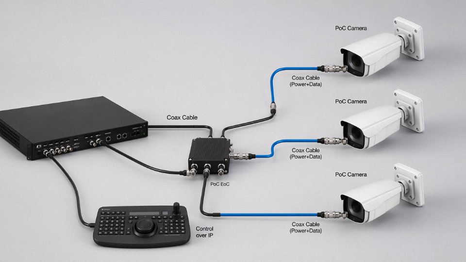
This changes the engineering considerations significantly. Every passive component in the path — splitters, baluns, surge arresters, patch panels — needs to handle the combined RF-plus-DC environment without degrading either. A splitter that works fine for pure RF will introduce insertion loss or DC blocking behavior that kills the camera’s power supply or distorts the video. Amplifiers need to be PoC-compatible, meaning their internal circuitry can tolerate and pass the DC rail without saturating or creating ground loops.
The cable itself matters too. Higher DC current means real resistive heating over long runs, and the center conductor’s cross-section determines how much voltage actually arrives at the camera versus what’s lost in the cable. On a 200 m RG-59 run — not unusual in a perimeter security layout — you can lose several volts to cable resistance alone, potentially dropping below the camera’s minimum input voltage. Upsizing to RG-6 or specifying a cable with a larger-gauge solid copper center conductor addresses this directly, though it also increases material cost and conduit fill.
The overarching point: the voltage present on an operating coax system is often a composite of signal, bias, and supply — and the cable’s voltage rating, its component compatibility, and its conductor sizing all need to be evaluated against the full picture, not just the RF signal level alone.
Coax in Industrial and Harsh-Environment Applications: Voltage Stress, Shielding, and EMI Concerns
Industrial coaxial cable installations bear almost no resemblance to the RG-6 drop cable running from a satellite dish to a living room TV. On an oil and gas platform, a substation perimeter, or a remote SCADA radio tower, the cable is simultaneously a precision RF transmission line and a physical object sitting inside one of the most electrically hostile environments humans build. The voltage stress question becomes genuinely complicated — and getting it wrong has consequences that go well beyond a degraded signal.
Where Industrial Coax Actually Gets Used
Wireless sensor networks on offshore platforms and refineries typically use coaxial feedlines to connect 900 MHz or 2.4 GHz antennas to field-mounted radios that report pressure, flow, and temperature data back to a DCS. These runs are rarely clean. The cable gets cable-tied to structural steelwork, routed through cable trays shared with 440 V motor leads and sometimes 6.6 kV medium-voltage bus bar runs, and left exposed to humidity, H₂S-laden atmospheres, and cyclic thermal stress. Substation perimeter CCTV is a similar situation — the coax from a pan-tilt-zoom camera on a 110 kV or 220 kV yard fence might run 80–150 m back to the control building, often near earthing conductors that carry significant fault current impulses during switching events.
None of the signal voltages on these cables is anything alarming. An RF signal from a SCADA radio transmitter at 1–5 W output produces peak voltages in the range of roughly 10–20 V on the feedline. That is not the danger. The danger is what the surrounding electrical environment does to the shield.
Induced Voltage: Capacitive and Inductive Coupling
A coaxial cable routed in parallel with a high-voltage cable — even with a few centimetres of physical separation — is exposed to both capacitive and inductive coupling mechanisms. Capacitive coupling is a function of the mutual capacitance between conductors and the rate of voltage change (dV/dt) on the HV line; inductive coupling is proportional to the mutual inductance and the rate of current change (dI/dt) in the power circuit. In steady-state conditions, induced voltages on the coax shield might be low enough to ignore. During a fault, a switching transient, or a lightning strike on nearby infrastructure, the induced pulse can reach hundreds of volts — easily enough to break down a marginal connector, damage the input stage of a radio, or create a shock hazard for a technician who happens to be handling the cable at the wrong moment.
IEC 62305 (protection of structures and electrical and electronic systems against lightning) is the standard that most directly governs this for antenna-connected coaxial cables in industrial facilities. It requires surge protective devices (SPDs) at the cable entry point to any building or protected zone, and it specifies bonding of the coax shield to the facility earth at both ends — a practice that creates a ground loop for low-frequency noise but is unavoidable when the alternative is an unbonded shield accumulating induced energy. In practice, RF engineers sometimes push back on both-ends bonding because of the interference it introduces; the compromise in well-designed industrial systems is a hybrid SPD that bonds the shield through a low-impedance path only for transients above a set threshold.
Routing coaxial cable in parallel with 6.6 kV or 11 kV power cables without surge protection can induce dangerous voltages on the coax shield even though the cable itself carries only low-level RF signals.True
Inductive and capacitive coupling from adjacent high-voltage conductors can produce transient voltages on the coax shield during fault events or switching operations, regardless of the signal level on the cable's inner conductor. IEC 62305 addresses this risk specifically for antenna-connected coaxial cables.
Shield and Jacket Selection Under Real Conditions
Standard single-braid coax — the kind you would use for a cable TV connection — has a transfer impedance somewhere in the range of 15–50 mΩ/m at 100 MHz, depending on braid coverage and construction quality. That is adequate for a clean indoor environment. It is not adequate when the cable is 2 metres from a variable-frequency drive or a medium-voltage switchgear panel.
Double-shielded construction — a bonded foil layer plus an overlapping braid — brings transfer impedance down to below 5 mΩ/m at 100 MHz in quality cables. The foil handles high-frequency interference where braid coverage becomes geometrically imperfect; the braid carries low-frequency and DC ground currents and gives the connector something mechanically robust to terminate against. For SCADA radio feedlines and substation CCTV runs, this is the minimum sensible specification.
Jacket selection deserves as much attention as the shielding. LSZH (low smoke, zero halogen) compounds meeting IEC 60332-3 flame spread requirements are the right choice for cables running in enclosed cable trays inside a processing facility or control building — ordinary PVC jackets produce toxic hydrogen chloride gas in a fire, which is unacceptable in confined spaces where personnel are evacuating. For outdoor antenna runs over 100 m, a solid PE jacket rated for UV resistance and direct burial is usually the correct answer; the PE resists moisture ingress and won’t embrittle from UV exposure the way thin LSZH compounds sometimes do after several years in direct sunlight. In geographies with extreme summer temperatures — a desert substation site, for instance — check the jacket’s continuous service temperature rating before specifying. Some standard LSZH compounds are only rated to around 70–75 °C, which a cable surface sitting in direct sun at 45 °C ambient can approach faster than you might expect.
One operational point that often gets missed in procurement specifications: the connector is the weakest link in outdoor industrial coax systems, not the cable. A correctly specified double-shielded PE-jacketed cable terminated with an uncorrosion-protected N-type connector using hand tools rather than proper crimping equipment will fail from moisture ingress at the connector interface long before the cable itself shows any degradation. Weatherproofing tape and proper connector selection — stainless-body connectors with IP67 or better ratings for outdoor and washdown environments — should appear in the cable assembly specification, not just the procurement note.
For separation distances from power cables, IEC 61918 and facility-specific EMC management plans typically call for a minimum of 200–300 mm between coaxial signal cables and low-voltage power cables in shared trays, with physical separation barriers where that clearance cannot be maintained. Near medium-voltage conductors at 6.6 kV or above, the separation guidance increases substantially, and the details depend on the specific fault level of the installation.
Selecting the Right Coaxial Cable Specification: A Procurement Checklist for Project Engineers
Getting the specification wrong at the RFQ stage is where most coaxial cable procurement problems actually start. By the time a contractor is on-site and discovers the cable won’t pass the fire inspection, or the installer realizes the outdoor run is already wicking moisture after one rainy season, the cost of the error has multiplied several times over. A structured checklist before the RFQ goes out saves that pain.
Confirm Operating Frequency and Acceptable Attenuation
Start here, not with the cable type name. Attenuation is expressed in dB per 100 m at a specified frequency, and that number climbs steeply as frequency rises — so your worst-case loss always occurs at the top of your operating band. RG-6 quad-shield running at 50 MHz is a non-issue; the same cable at 3 GHz may exceed your link budget on a run longer than 20–25 m. Pin down your highest operating frequency first, then calculate the maximum allowable insertion loss for your longest run. Work backward to a cable type from there, not forward from a catalog name.
Verify Maximum Working Voltage — Including Injected DC or AC
This is where engineers frequently underestimate the actual stress on the cable. The RF signal itself is rarely the limiting factor. What catches people out is PoC (Power over Coax), LNB bias supplies (typically 13–18 V DC), or CATV trunk amplifier powering (often 30–90 V AC). Add any realistic transient or surge margin on top of the steady-state supply. If your system injects 60 V AC for trunk amplifier powering, a cable rated only for dry indoor signal use may not give you adequate margin — check the manufacturer’s voltage rating against total applied voltage, not just signal level.
Lock Down Impedance and Verify the Entire Signal Path
50 Ω and 75 Ω are not interchangeable. They look physically similar, and an F-to-BNC adapter will mechanically mate mismatched systems. The result is a standing-wave ratio problem that degrades signal at every impedance discontinuity. Specify impedance on the RFQ, and explicitly require that connectors, splitters, combiners, and any passive components are matched to that impedance. One mismatched barrel connector in a distribution chain can cost hours of troubleshooting.
Define the Installation Environment Before Choosing Jacket and Shielding
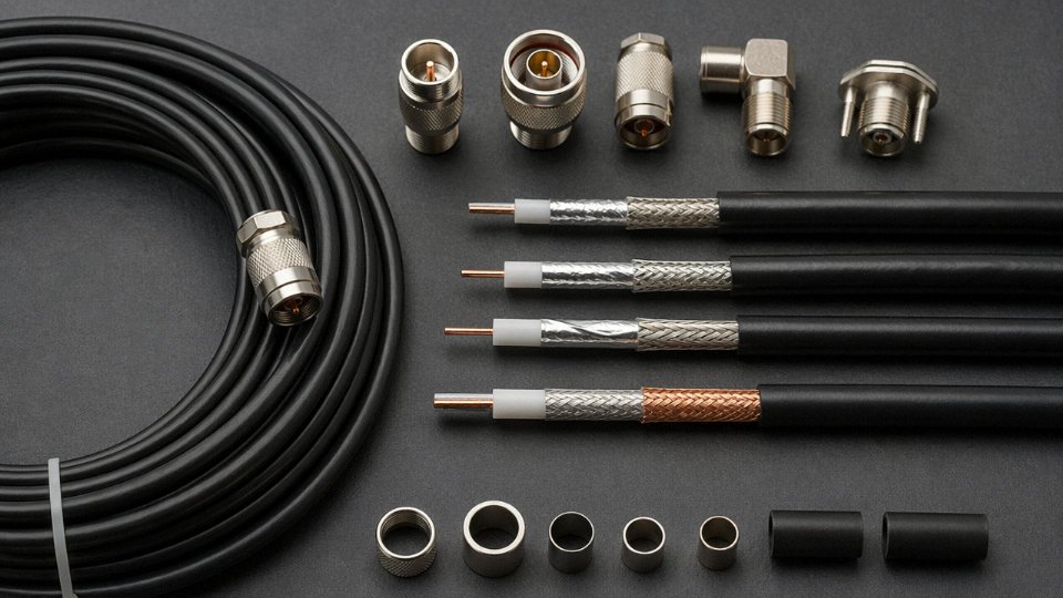
Indoor plenum, riser, outdoor aerial, direct burial, industrial conduit, armored underground — each demands a different jacket compound and often a different shielding architecture. Using standard PVC-jacketed indoor RG-6 in a direct-burial outdoor antenna run without a flooded or gel-filled construction typically results in cable failure within 2–3 years. Moisture migrates along the dielectric, the foam polyethylene degrades, and attenuation climbs before the cable shows any external damage. Specify UV resistance for any exposed outdoor run, and for industrial conduit environments consider whether a dual-jacket or armored construction is warranted based on mechanical abuse and chemical exposure.
Confirm Applicable Certifications Up Front
UL 444 for signal cable, IEC 61196 series for coaxial connector and cable performance, RoHS and REACH compliance for EU supply chains, and any regional fire or smoke ratings (CPR Euroclass in Europe, NEC plenum ratings in North America) — these need to be specified on the RFQ, not requested after the order is placed. Certification paperwork gaps cause customs delays and project holdups that dwarf the cable cost itself.
The Real Cost of Over- and Under-Specification
Over-specifying is real money. Substituting LMR-400 where RG-6 adequately handles the frequency and loss budget inflates material cost by roughly 3–5x, depending on run length and market conditions, with zero measurable signal benefit below around 300 MHz. Under-specifying costs more — failed cables, return visits, and customer disputes are expensive in ways that don’t show up on the original BOM.
Using standard indoor RG-6 without a flooded or gel-filled jacket in direct-burial outdoor installations causes moisture-related cable failure within approximately 2–3 years.True
Foam polyethylene dielectric in standard RG-6 absorbs moisture when the jacket is breached or when moisture wicks through cut ends, progressively increasing attenuation and ultimately causing signal failure; flooded or gel-filled constructions are specifically designed to block longitudinal moisture migration in burial applications.
Working With a Manufacturer Who Can Customize
Standard catalog cable covers most applications, but projects with unusual outer diameter constraints, dual-jacket requirements, specific armor types, or documentation packages for regulated markets often need direct manufacturer engagement. Jinda’s engineering team supports project-specific coaxial cable customization — custom OD, dual-jacket designs, armored variants, and full compliance documentation — backed by vertical integration from wire drawing through finished cable testing. That matters in practice because it means one point of accountability for the entire specification, rather than chasing separate suppliers for cable, testing reports, and compliance declarations when an inspection is three weeks out.
Frequently Asked Questions About Coaxial Cable Voltage Classification
Is coaxial cable classified as low voltage under the NEC?
Not in the way most people assume. NEC Article 820 carves out a separate category for coaxial cables — they are treated as communications cables, not low-voltage power conductors, so the standard power-wiring rules in NEC Chapter 3 simply don’t apply to them. That distinction matters more than it sounds. Your coax installation won’t be governed by the same conduit fill calculations, conductor spacing rules, or ampacity tables that cover 120 V branch circuits. The one hard limit Article 820 does impose: any current carried on the outer conductor must not exceed 60 V RMS. Everything above that threshold pulls you into a different regulatory conversation entirely.
Under NEC Article 820, coaxial cables are classified as communications cables with their own installation rules, separate from low-voltage power conductor requirements in NEC Chapter 3.True
NEC Article 820 specifically governs coaxial communications cables and establishes separate requirements distinct from Chapter 3 power wiring methods, including a 60 V RMS limit on any current carried by the outer conductor.
Can I run coaxial cable in the same conduit as 120 V or 240 V power wiring?
No. NEC 820.133 is explicit on this point, and inspectors enforce it consistently. Coaxial cables cannot share a conduit, outlet box, or raceway with conductors for electric light, power, or Class 1 circuits — unless a permanent barrier physically separates them inside that enclosure. The rationale is twofold: voltage induction from an adjacent 120 V or 240 V conductor can corrupt a weak RF signal beyond recovery, and a fault condition on the power conductor can impress a dangerous voltage onto the coax shield. In practice, running them in parallel even in separate conduits with minimal separation can cause measurable interference on sensitive analog video or RF systems. Keep them physically apart wherever the run allows it.
What is the maximum DC voltage I can safely inject into coaxial cable for PoC or LNB applications?
Standard 75 Ω coaxial cables like RG-6 and RG-11 can typically handle up to 48 V DC on the center conductor for Power over Coax camera installations. LNB bias for satellite systems runs 13–18 V DC, well within that limit. The cable itself usually isn’t the weak point. The real failure mode in these systems is the passive devices inline — splitters, amplifiers, diplexers — which often carry voltage ratings of 24 V DC or lower. A 48 V PoC system fed through a passive splitter rated to 24 V is a latent failure waiting for the next maintenance cycle. Always pull the spec sheet for every passive component in the signal path before you finalize a PoC or LNB design. This is the step that gets skipped most often.
Does coaxial cable need to be grounded, and does grounding affect its voltage classification?
Grounding is mandatory under NEC 820.93: the outer shield must be bonded to the building grounding electrode system at the point of entry. What grounding does not do is change the cable’s voltage classification — a grounded RG-6 is still a communications cable, not a power conductor. What it does do is limit the shield voltage during a lightning event or accidental power-line contact to something close to building ground potential, instead of letting it float to a level that damages equipment or creates a shock hazard. Skipping this step is common in residential installs and occasionally in small industrial panels. When a nearby lightning strike couples energy into an ungrounded coax shield, the resulting transient has damaged more than a few satellite receivers and security camera input cards. A proper ground bond at entry costs almost nothing.
How does Jinda ensure coaxial cable voltage ratings are consistent across large production runs?
Every production reel undergoes 100% dielectric voltage withstand testing per IEC 61196-1, with the test voltage applied between center conductor and outer shield for a minimum of 60 seconds. No sampling — every reel. Capacitance, attenuation, and characteristic impedance are verified against the specification sheet before the reel leaves the production floor, and full test reports ship with each delivery lot so procurement teams have documentation for incoming inspection or third-party audits. For large project orders — particularly for trunk or hardline cable going into cable TV headend builds or distributed antenna systems — Jinda’s technical team can provide lot-specific test data correlated to reel serial numbers, which simplifies traceability when you’re managing a multi-site installation and need to isolate a suspect batch without pulling everything.
Why Coaxial Cable Source and Manufacturing Quality Directly Affect Voltage Performance
Voltage ratings printed on a datasheet are only as reliable as the manufacturing process behind them. This is the part that procurement teams tend to overlook when sourcing coaxial cable on price alone — and it’s where real field failures originate.
Dielectric Wall Tolerance: The Hidden Variable in Breakdown Voltage
The dielectric layer — solid PE, foam PE, or PTFE depending on cable type — is the primary insulating barrier between the center conductor and the braid. Its rated dielectric strength assumes a consistent, uniform wall thickness across the entire cable length. In practice, that assumption only holds if the extrusion line is properly controlled.
Inconsistent dielectric wall thickness is one of the most common quality defects in lower-grade coaxial cable, and it’s often invisible without cross-section inspection. A wall that nominally measures 1.8 mm but varies between 1.4 mm and 2.1 mm along its run contains localized thin spots. Under sustained operating voltage — even well within the nominal rating — those thin spots concentrate the electric field stress and degrade faster than surrounding material. The cable doesn’t fail immediately; it fails six months or two years into service, which is the worst possible outcome because it looks like a system fault, not a cable quality problem.
Controlled extrusion targeting ±0.05 mm wall tolerance is the practical threshold for maintaining rated voltage performance along the full reel length. Achieving that repeatably requires in-line diameter gauging, stable melt-temperature control, and disciplined process monitoring — none of which are free. They’re also the reason a well-manufactured reel costs more than a reel that merely passes a spot-check at the end of the line.
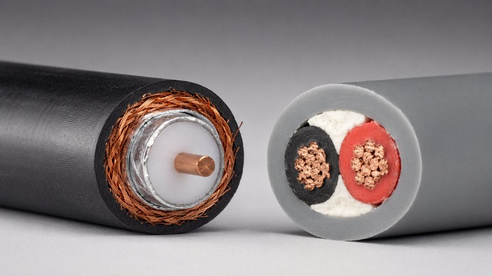
Inconsistent dielectric wall thickness in coaxial cable can cause premature insulation breakdown under normal operating voltage stress.True
Thin spots in the dielectric create localized regions of elevated electric field intensity. Under sustained voltage, these regions experience accelerated dielectric aging and can fail well below the cable's nominal voltage rating — a well-documented failure mode in extrusion-manufactured insulated cables.
Conductor Purity and Long-Term Thermal Stability
Center conductor purity matters more than most specs acknowledge, particularly in PoC (Power over Coax) and LNB bias applications where 12 V to 48 V DC at currents up to 1 A or more runs continuously alongside the RF signal. Oxygen-free copper (OFC) at 99.95% purity carries that supply current with lower resistive heating than electrolytic-tough-pitch copper, and far lower than copper-clad steel (CCS).
CCS conductors are a legitimate cost-reduction choice — but only in pure signal applications where no DC supply voltage is injected. Use CCS in a PoC-enabled CATV or IP camera distribution system and you’re running higher conductor resistance, more I²R heating, and accelerated dielectric aging. Over a 20-to-25-year design life, the difference in thermal stress accumulation between OFC and CCS under a 48 V / 1 A load is not trivial.
In my experience, CCS center conductors show up in bulk commodity cable more often than they should, sometimes without clear labeling. Specifying conductor purity explicitly in your RFQ — not just “copper center conductor” — closes that substitution risk.
Manufacturing Scale and Supply Consistency
Single-reel quality is not the hard part. Supplying consistent quality across a 50,000-meter infrastructure project, or across repeated OEM production batches over multiple years, requires a different level of manufacturing infrastructure entirely.
Jinda has operated since 1987 across five production bases covering 470,000 m² of manufacturing space, with over 1,000 employees and an integrated structure running from R&D through production, quality documentation, and after-sales engineering support. Serving customers in more than 50 countries means the quality system has been stress-tested against IEC, NEC, and regional compliance requirements in parallel, not sequentially. For procurement managers running large infrastructure programs or long-term OEM supply agreements, that kind of production depth and documentation capability is what separates a manufacturer from a trading company with a catalog.
Voltage performance is ultimately a manufacturing quality problem. The standards tell you what to achieve; the production process determines whether you actually achieve it, reel after reel, year after year.