Specifying the wrong cable type doesn’t just mean a failed inspection — it means unplanned downtime, scrapped installation runs, and in worst cases, a fire investigation. Procurement managers who treat cable selection as a checkbox exercise routinely discover mid-project that the conductor cross-section is undersized for actual load cycles, or that the insulation compound degrades inside 18 months in a mildly corrosive environment. The rework cost alone can run 3–8× the original cable purchase price, depending on how deep into a build the error surfaces.
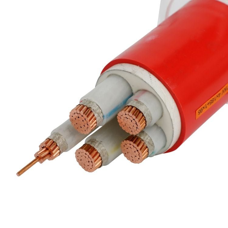
Cable uses copper or aluminum conductors (copper covering roughly 60–65% of global power cable use, aluminum 30–35%), insulated with XLPE, PVC, or EPR depending on voltage class and environment, protected by bedding layers, armor, and an outer sheath selected for mechanical and chemical exposure. The specific combination is driven by voltage rating, installation method, ambient conditions, and the relevant regional standard.
What makes this genuinely interesting — and what most sourcing guides skip past — is that the cable itself is a small manufacturing system. Each layer exists because some failure mode is probable without it, and the interactions between layers matter as much as the materials themselves. Understanding that logic changes how you specify, how you audit a supplier’s production line, and how you catch substitution before it reaches the field.
High-Voltage and Medium-Voltage Feeder Cables: Bringing Grid Power into the Production Floor
A large cable manufacturing plant — the kind running multiple continuous vulcanization lines, wire drawing machines, and copper rod breakdown equipment simultaneously — pulls anywhere from 5 MW to 20 MW of installed electrical load, depending on product mix and shift pattern. That power has to get from the utility grid to the production floor somehow, and the cables doing that job are under more scrutiny than most procurement teams initially expect.
Typical Utility Intake Arrangement
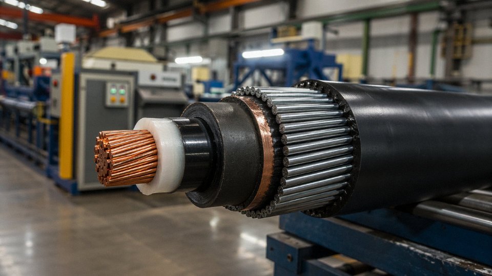
Most medium-to-large cable plants take grid supply at 10 kV or 35 kV — 10 kV being the norm in urban Chinese industrial parks, 35 kV more common where the plant sits closer to a regional substation or where demand exceeds roughly 8–10 MW. The utility feed terminates at an on-site main substation, usually one or two dry-type or oil-immersed transformers stepping voltage down to 0.4 kV for distribution boards and motor control centers. Between that substation and the utility handoff point, you’re looking at armored underground cable runs, often 100 m to 400 m depending on site layout and where the grid company plants its metering cabinet.
These feeder runs are not glamorous, but getting them wrong means transformer tripping, production shutdowns, and in worst cases, arc flash events that can take a substation out of service for weeks.
Conductor Choice: Copper Versus Aluminum at MV Level
Copper’s resistivity sits at roughly 1.72 × 10⁻⁸ Ω·m; aluminum runs around 2.82 × 10⁻⁸ Ω·m. That gap matters for cross-section sizing, but it’s not the whole story. Copper handles repeated thermal cycling at joints far better — critical at the transformer termination where load swings with production shifts. It’s also significantly more forgiving when field jointing quality is inconsistent, which in a busy plant environment is a real risk.
Aluminum, at roughly 30% of copper’s weight and typically 40–55% of the cable cost depending on LME pricing at the time of order, makes a compelling case for long, straight underground feeder runs where you can control termination quality and aren’t dealing with frequent flexing. A 200 m direct-burial run under factory paving is exactly where a properly specified aluminum MV cable performs well. The savings on a three-core 95 mm² or 120 mm² run can be meaningful at project scale. The trade-off is termination labor and material — aluminum oxide forms fast, compression lugs need antioxidant compound, and the jointer needs to know what they’re doing.
Aluminum MV cable costs approximately 40–55% less per meter than equivalent copper MV cableTrue
The actual differential depends on prevailing LME copper and aluminum prices, conductor cross-section, and cable construction complexity. The range is accurate under typical market conditions but narrows when aluminum prices spike or when copper is purchased on long-term contract.
Insulation Systems: Why XLPE Dominates Above 1 kV
For any feeder cable above 1 kV, XLPE has largely displaced paper-insulated lead-covered (PILC) and solid PVC constructions. The thermal ceiling — 90°C continuous conductor temperature, with short-circuit withstand ratings that allow up to 250°C for fractions of a second — gives XLPE a current-carrying advantage over PVC, which tops out around 70°C. Dielectric losses are low, moisture resistance is good for direct-burial applications, and the material doesn’t require the oil-impregnation maintenance that PILC demands.
EPR (ethylene propylene rubber) insulation is worth considering in specific situations: plant extensions near coastal environments, any run with significant thermal cycling, or applications where some cable flexibility during installation matters. EPR handles repeated bending better than XLPE and maintains stable dielectric properties across a wider temperature swing. It costs more — typically 15–25% premium over XLPE of equivalent rating — and that premium is usually only justified where the operating environment genuinely demands it.
Armor Selection: SWA Versus STA
Steel wire armor (SWA) is the right choice for direct-burial trenches under paved factory yards. The helical wire construction resists tensile stress during pulling, handles ground movement, and provides mechanical protection against accidental dig-in. For a 200 m underground run, you want SWA.
Steel tape armor (STA) suits fixed indoor tray or duct installations where tensile load isn’t a concern but radial crush resistance is. Indoor cable routes on ladder trays, passing through cable transit frames, or running through steel conduit sections — those are STA territory. Using SWA in a tray-mounted indoor run isn’t wrong, but it’s heavier, stiffer, and you’re paying for mechanical performance you don’t need.
Standards You Need on the Specification Sheet
| Standard | Scope | Notes |
|---|---|---|
| IEC 60502-2 | Power cables 6 kV–30 kV | Core reference for design and testing |
| IEC 60228 | Conductor classes | Specifies Class 2 stranded for fixed installation |
| GB/T 12706 | Chinese national standard | Harmonized with IEC 60502; required for China-supplied projects |
| UL listing (where applicable) | North American export projects | Verify cable construction meets UL 1072 or applicable UL standard |
Practical Sizing: A 2 MW Extrusion Line at 10 kV
A single large rubber extrusion or CV line drawing 2 MW at 10 kV, fed over a 200 m underground run, gives you a useful benchmark. At 10 kV, 2 MW equates to roughly 115 A at unity power factor (closer to 130–140 A at a realistic 0.85 pf for motor-heavy industrial loads). IEC 60502-2 tables for XLPE-insulated, SWA, direct-buried cable in standard soil thermal resistivity — 1.0 K·m/W is the IEC reference condition, though compacted sandy soil under paving can run higher — point toward a 3-core 50 mm² copper conductor as adequate for thermal rating, but short-circuit withstand at 10 kV system fault levels of 12–16 kA for 0.5–1 second typically pushes the minimum to 70 mm², sometimes 95 mm² depending on the protection relay clearing time confirmed with the utility. Voltage drop over 200 m at that cross-section is well under 1% — not the limiting factor here.
With aluminum, you’d step up one cross-section size: 95 mm² or 120 mm² to match the same thermal and fault-withstand performance. The cable is cheaper; the termination hardware and labor cost more. Run the numbers for your specific project before assuming aluminum is always the lower-cost option once everything is accounted for.
Low-Voltage Power and Motor Feed Cables: The Workhorse Circuits of Wire Drawing and Extrusion Lines
Walk any large cable production floor and the medium-voltage feeder gets the attention — it’s the dramatic stuff, big terminations, oil-filled switchgear, safety interlocks. But the real workhorse is the 0.6/1 kV network threading through cable trays and conduit to every motor on the line. Hundreds of circuits. Constant duty. And in a cable factory specifically, the electrical environment those cables operate in is genuinely harsher than most industrial plants of comparable size.
The Load Inventory Is Not Trivial
Start with what’s actually connected. A modern wire drawing machine — a continuous fine-wire or medium-wire machine pulling copper or aluminum down through progressively smaller dies — can draw anywhere from 90 kW to roughly 800 kW per unit, depending on the number of passes and target wire gauge. Planetary stranders, caterpillar capstans, and armoring machines tend to fall in the 30–250 kW range. Extrusion lines are the real power consumers: a 150 mm extruder screw drive alone can run 200–400 kW, plus separate drives for the traction unit, caterpillar haul-off, and take-up. Add high-current resistance testing benches, spark testers running at 6–15 kV DC (their power supplies draw significant LV current), climate-controlled cable drums, and compressed air systems, and you are looking at a facility where practically every major load runs at or near full capacity for extended stretches. Cyclic loading — stranders that reverse tension, take-ups that accelerate and decelerate — generates current surges that a simple steady-state cable sizing calculation will underestimate.
VFD Compatibility: Where Most Facilities Get It Wrong
Virtually all of those drives are now variable-frequency, and that changes everything about what you need from the motor feed cable. VFD output is not a clean sine wave. It’s a pulse-width-modulated signal with voltage rise times (dV/dt) typically in the range of 500–2000 V/µs, sometimes higher with newer IGBT switching at 8–16 kHz carrier frequencies. That dV/dt gradient drives partial discharge activity in any insulation void or microvoid — even ones too small to fail a standard factory AC withstand test at 50 Hz. Over months of continuous operation, those partial discharges erode insulation from the inside.
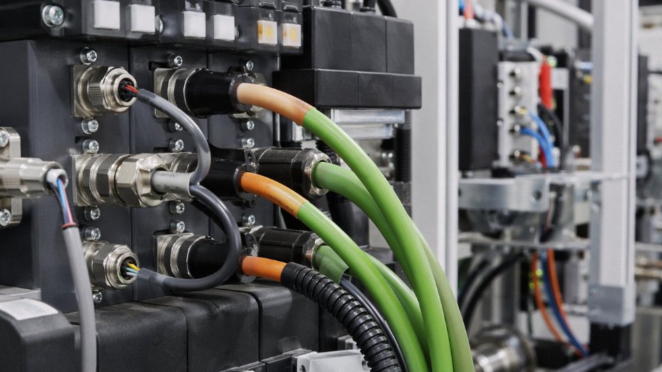
The practical fix is twofold: use XLPE or EPR insulation rather than standard PVC (both have significantly lower permittivity, which reduces capacitive charging current and limits the stored energy available for discharge), and apply a collective copper braid or copper tape screen over the cable core assembly. The screen provides a low-impedance return path for high-frequency leakage currents — without it, those currents find their way back through structural steelwork and cable trays, causing EMI problems in control systems and measurable corrosion at grounding points over time. I’ve seen this become a real headache in plants that upgraded drives piecemeal without upgrading the cable specification.
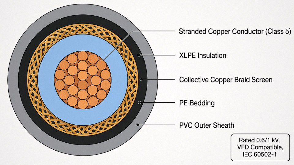
Cross-sections for main drive feeds typically run 16–300 mm², with conductor class depending on installation: Class 2 stranded copper for fixed runs in trunking, Class 5 flexible copper anywhere there’s a moving connection or frequent reconfiguration. IEC 60228 covers both; specifying the class explicitly in your procurement documents avoids a lot of back-and-forth.
The Neutral Conductor Problem Nobody Budgets For
Three-phase systems with heavy VFD and switch-mode power supply loads generate substantial third-harmonic (and triplen-harmonic) currents. Unlike fundamental-frequency current, third harmonics from all three phases add arithmetically in the neutral rather than canceling — in a heavily loaded non-linear circuit, neutral current can reach roughly 1.4–1.73 times the phase current. Standard four-core cables with a reduced neutral conductor (common in European practice for linear loads) are genuinely undersized for this. The cable overheats, the insulation degrades faster than any life calculation predicted, and you eventually get a neutral failure that is both dangerous and hard to diagnose.
The correct specification for distribution circuits feeding significant VFD loads: full-size neutral, same cross-section as the phase conductors. For the worst circuits — dense VFD panels, testing equipment banks — an oversized neutral (one step up) is worth considering. It adds maybe 8–12% to cable cost on that circuit. Compare that to a neutral burnout inside a distribution board.
In three-phase circuits with predominantly non-linear loads such as VFDs, neutral current can exceed phase current by up to 73% due to triplen harmonic summation.True
Third-harmonic currents (and all odd triplen harmonics: 3rd, 9th, 15th…) are zero-sequence quantities that do not cancel in the neutral conductor as balanced fundamental currents do. In a fully loaded system of non-linear loads, the theoretical maximum neutral current is √3 times phase current, or approximately 173% — widely referenced in IEC and IEEE harmonic guidance documents.
Voltage Drop: Tighter Limits Than the Code Requires
IEC 60364 and most national industrial codes permit up to 5% voltage drop from the supply point to the final load terminal. That’s fine for a pump or a fan. For a precision wire drawing machine where the drive is actively regulating wire tension and speed to tolerances of fractions of a percent, a 4–5% voltage sag under load can induce torque instability — inconsistent wire diameter, broken wire, scrap. In practice, 2–3% is the sensible design limit for precision drive circuits, which means either shorter cable runs, larger conductor cross-sections, or both. Running the voltage drop calculation is a five-minute task; re-pulling undersized cable after commissioning is a two-day job.
An Operational Advantage Specific to Cable Manufacturers
One genuinely useful thing about being a cable manufacturer: the electrical test benches already exist on site. AC withstand testing, partial discharge measurement at specified voltage levels, insulation resistance — this equipment is in the quality lab to certify outgoing product to IEC 60502, IEC 60840, or whatever standards apply to customer orders. There’s no technical reason those same benches can’t be used on internally installed cables before commissioning and as part of a periodic maintenance program. In most factories that would require bringing in a specialist contractor and renting equipment. Here it’s already paid for.
That means a cable manufacturer can, with modest procedural discipline, maintain a higher verified confidence level in the integrity of its own plant wiring than almost any other type of industrial facility. Whether most factories actually do this is a different question — maintenance culture varies enormously — but the capability is there.
Control, Instrumentation, and Signal Cables: Keeping Extrusion Temperature, Tension, and Tolerance in Spec
Walk the cable tray routes in any large extrusion hall and you’ll see the real problem immediately. Within a metre or two of each other, you have 690 V motor feeders carrying hundreds of amps, VFD output cables switching at 4–16 kHz, induction annealing furnace busbars running at 50–500 Hz harmonics, and — sandwiched right between them, sometimes — a thin pair of wires carrying a 4–20 mA signal that represents the melt temperature at a crosshead die. The tolerance on that temperature might be ±2°C. The noise environment is trying to impose errors ten times that.
This is where control and instrumentation cable selection stops being a box-ticking exercise.
The Signal Environment Is Genuinely Hostile
Frequency converters generate common-mode noise that couples capacitively into adjacent cables. Induction furnaces radiate strong alternating magnetic fields — the kind that induce millivolt-level voltages in any loop with area greater than a few cm². Overhead cranes add impulsive transients every time contactors switch. None of this is unusual for a heavy industrial plant, but a cable factory concentrates all of it in a relatively compact footprint, and the product being made means the engineering team has no excuse for not knowing better.
Unshielded instrumentation cable in this environment is not a cost saving. It’s a liability that will show up as process drift, rejected reel lengths, or unexplained extrusion faults — usually at 2 a.m.
Shielding Hierarchy: Why One Layer Is Rarely Enough
The standard approach for multi-pair instrumentation cables in high-EMI environments uses two shielding levels, and for good reason. Individual pair foil shields — typically aluminium/polyester laminate — address differential-mode noise, meaning interference that appears as a difference between the two conductors of a pair. This matters most for analogue 4–20 mA loops and Pt100 circuits, where even a few millivolts of coupled noise translates directly into a false reading.
The overall shield — braided copper, coverage ≥ 85% — handles common-mode interference, the kind that shifts both conductors together relative to system ground. Below 85% coverage, low-frequency magnetic fields start leaking through the braid gaps. Drain wires, one per individual foil shield and one for the overall braid, give you a low-resistance termination path back to the cabinet earth. Terminate them at one end only (the control cabinet end, normally) to avoid creating a ground loop — a mistake that causes as much noise as having no shield at all.
Protocol-Specific Requirements Are Not Interchangeable
A 4–20 mA loop cable and a Profibus-PA segment cable look superficially similar but are engineered to different parameters. Profibus-PA requires a characteristic impedance of 100 Ω ± 20%; using a generic instrumentation cable with impedance outside that window causes signal reflections on segments longer than roughly 50–80 m, and you’ll see intermittent communication faults that are maddeningly difficult to trace.
Encoder cables for servo-driven capstans and tension-control systems have their own demands. High-speed position feedback — pulse trains running at 200 kHz or above — needs individually shielded pairs with mutual capacitance below 100 pF/m. Higher capacitance smears the pulse edges, which the drive interprets as position jitter. The result is tension hunting on the payoff or takeup, which means dimensional variation in the finished wire. Capacitance spec is not a footnote on the datasheet; it’s the number procurement should verify before approving a substitute.
Temperature Sensor Wiring: The Metallurgy Matters
Pt100 and thermocouple extension cables are a specific failure mode worth calling out. Standard copper control cable works fine for carrying digital signals or 24 V logic — but run it from a thermocouple junction back to an input card and you’ve introduced two additional thermoelectric junctions wherever the copper meets the thermocouple alloy. At elevated ambient temperatures, those parasitic EMFs add up to real measurement error. Compensating cable for Type K thermocouples uses chromel/alumel alloy conductors specifically to cancel this effect. Substituting standard cable because it’s in stock is a common shortcut with a predictable consequence: your temperature readings drift with ambient, not with the process.
Using standard copper control cable in place of matched-alloy thermocouple extension cable introduces parasitic thermoelectric EMFs that cause temperature measurement errors.True
Dissimilar metal junctions between copper conductors and thermocouple alloy conductors generate their own thermoelectric voltages (Seebeck effect). At ambient temperatures above roughly 30–40°C, these can produce errors of several degrees Celsius on Type K or Type J circuits — enough to cause real process control problems in an extrusion line.
Routing and Segregation: The Rule That Gets Ignored First
IEC 61918 and general industrial practice call for a minimum 200 mm physical separation between power cables and instrumentation cables, with metallic dividers used where separation is impractical. In a busy extrusion hall where tray space is always contested, this rule is the first one to get compromised during a plant expansion or a rushed retrofit.
The practical consequence of ignoring it showed up in a retrofit on a 90 mm extruder crosshead control loop. The line had been running with six-pair, individually and overall-shielded 0.5 mm² instrumentation cable, correctly installed — until a new VFD-driven haul-off was added and its motor feed cable was dressed into the same tray for convenience. Within a week, the crosshead temperature control was oscillating ±5–7°C. The PID wasn’t the problem. The thermocouple signal was being corrupted by switching noise from the VFD cable running parallel for about 4 m. Adding a grounded steel divider between the two trays and re-routing the VFD cable’s last 2 m solved it. Total cost: a few hours of an electrician’s time and some trunking. Downtime during diagnosis: roughly three shifts of unstable product.
Specifying the right cable is half the job. Where it runs, and what it runs next to, is the other half.
Fire-Resistant and Low-Smoke Zero-Halogen Cables: Protecting Lives and Machinery in a Polymer-Rich Environment
A cable factory is, by its nature, one of the higher fire-risk industrial environments you’ll find. Think about what’s actually on site at any given moment: tonnes of PVC compound in bulk bags, polyethylene and XLPE granules in hopper bins, drums of drawing lubricant, wire-drawing emulsion tanks, and — stacked floor to ceiling in the finished-goods warehouse — hundreds of loaded cable reels, each one a tightly wound coil of polymer insulation and jacketing. The fuel load per square metre easily exceeds that of a typical machine shop or assembly plant. A fire that gets into a reel storage area doesn’t smoulder; it runs.
That context is what makes the fire-protection cabling specification inside a cable factory genuinely non-trivial — and, frankly, where a lot of plant operators underinvest until an incident forces the conversation.
Understanding the Two Distinct Performance Tiers
People sometimes use “fire-resistant” and “LSZH” interchangeably. They shouldn’t. These are separate performance dimensions that address separate hazards.
Circuit integrity is about keeping a circuit alive during a fire. IEC 60331-1 and -2 define survival at temperatures ranging from 750°C up to around 950°C, for durations of 90 minutes at the lower end and up to 180 minutes for more demanding classifications. A circuit-integrity cable keeping a smoke exhaust fan running during evacuation is doing a completely different job than a cable that simply burns slowly.
LSZH (Low-Smoke Zero-Halogen) performance, tested under IEC 60754-1/2 and IEC 61034-2, limits hydrogen chloride equivalent emissions to below roughly 0.5% and restricts smoke obscuration so that exit signage remains visible during the early stages of a fire. In a PVC-heavy manufacturing environment, this matters enormously: burning PVC releases HCl at concentrations that are both directly toxic and highly corrosive to electronics, motor windings, and control gear — damage that often extends well beyond the fire zone itself.
The most critical circuits need both simultaneously. A fire pump starter cable that emits a dense, corrosive smoke cloud while heroically maintaining circuit continuity has only half-solved the problem.
Which Systems Are Mandatory Users
In practice, the following circuits should never be specified on standard cable regardless of cost pressure:
- Fire alarm loops — typically 2-core 1.5 mm², fire-rated, screened
- Emergency lighting distribution circuits
- Sprinkler system control and supervisory panels
- Smoke exhaust and pressurisation fan feeds (these are often the largest conductors in the fire-circuit group, potentially 10–35 mm² depending on fan motor size)
- PA/VA public address and voice alarm systems
- Fire pump starter and control cables
Mineral-insulated copper-clad (MICC/PYRO) cable is the traditional solution for the highest-integrity applications: it survives temperatures above 1000°C indefinitely, has essentially zero smoke output, and is mechanically robust. Its drawbacks are installation rigidity and cost. Mica-taped fire-resistant cables — where multiple layers of mica tape are applied directly over the conductor before the primary insulation goes on — offer more flexible installation and are now the dominant choice for most emergency system feeders. The mica layer is the key: mica retains its dielectric properties above 1000°C, so even after the outer LSZH jacket and inner polymer insulation have burned away, the circuit can remain intact.
Mica retains its dielectric strength above 1000°C, allowing mica-taped fire-resistant cables to maintain circuit integrity after polymer insulation has burned offTrue
Mica is a naturally occurring silicate mineral with a melting point above 1300°C and well-documented electrical insulation properties at extreme temperatures, which is the basis for its use in fire-resistant cable construction per IEC 60331.
Standards That Actually Show Up in Procurement Specs
The compliance picture is fragmented by market, which creates real problems for export-oriented manufacturers sourcing their own plant cables. IEC 60332-1 and -3 cover flame propagation for individual cables and installed bunches respectively — a distinction that matters because bundled cables in a cable tray burn very differently from a single cable in a test fixture. EN 50200 adds enhanced fire resistance requirements used widely across European projects. GB/T 19666 is the Chinese national standard covering flame-retardant and fire-resistant cable classifications, and any plant operating under Chinese building codes needs to verify compliance here specifically. For cables destined for UK projects or UK-supplied equipment, BS 7629 (fire-resistant) and BS 7846 (armoured fire-resistant) still appear in specifications regularly despite post-Brexit divergence.
The Containment Rule That Gets Ignored
Here’s where plants make a recurring mistake: routing fire-resistant cables in shared cable trays with ordinary power or control cables. The logic seems reasonable — the fire-resistant cable can survive, so why not share the tray? The problem is that the burning cable mass surrounding it will, under sustained fire conditions, defeat the circuit integrity performance the fire-resistant cable was specified to deliver. IEC standards and fire engineering guidance are consistent on this point: dedicated fire-rated conduit or trunking, physically segregated, with intumescent seals at every wall and floor penetration. Skipping the seals at penetrations is particularly common and particularly dangerous — it’s the point where smoke and flame travel between fire compartments and where your 180-minute circuit integrity rating becomes meaningless.
In a polymer-rich plant, the investment in correct fire-circuit segregation is not a regulatory compliance exercise. It’s the difference between an incident that triggers a suppression system and one that evacuates a building.
Reeling, Trailing, and Crane Cables: Handling the Mechanical Abuse of Continuous Motion in Production
Electrical stress gets most of the attention in cable specification. In a cable factory, though, some of the most punishing service conditions have almost nothing to do with voltage — they’re purely mechanical. Flex fatigue, torsion, oil contamination, and abrasion quietly destroy conventional cables in months when the application demands continuous motion.
Where the Movement Actually Happens
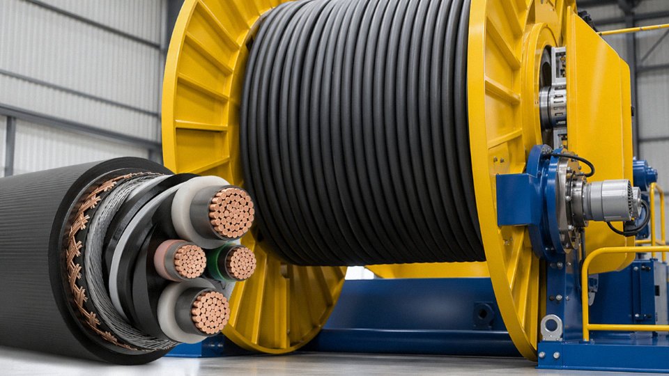
Walk a large cable factory floor and you’ll see overhead bridge cranes — commonly rated 20 to 50 tonnes for handling finished drum sets — traversing all day between winding lines, stranding machines, and dispatch bays. Below them, motorized pay-off reels accelerate and decelerate thousands of times per shift. Traversing take-up trolleys follow the lay of coiled product across the width of a winding station. Mobile testing carts get dragged along measurement benches. Every one of these moving systems feeds power and control signals through a cable that bends, twists, and scrapes continuously. None of them can use the same Class 2 stranded conductors you’d pull through conduit.
Conductor Design Is Where Flex Life Is Won or Lost
Standard Class 2 conductors — the kind used in fixed-installation 0.6/1 kV power cable — will typically survive fewer than 50,000 bending cycles before wire breakage begins at bend points. That sounds like a lot until you realize a busy crane or reeling drum might log that many cycles in a few weeks of three-shift production.
Class 5 and Class 6 fine-wire stranded conductors change the picture entirely. Individual wire diameters in the range of 0.1–0.4 mm, depending on total conductor cross-section and the specific standard, achieve 1 to 5 million bending cycles at the cable’s rated minimum bend radius — a factor-of-100 improvement, roughly. The stranding pattern matters too: rope-lay construction (bundles of bundles) distributes bending strain more evenly through the cross-section than simple bunch-lay, which tends to concentrate stress on wires at the outer layer. For reeling-drum applications specifically, rope-lay is usually the right call, even if it costs a bit more per metre.
Sheath Material Dictates Survival in the Real Environment
Crane and reeling cables in a polymer-processing plant face lubricating oils from drawing machines, cutting fluids, and whatever gets spilled near the winding stations — which is more than most engineers expect. PUR (polyurethane) sheathing handles this environment better than almost anything else: abrasion resistance is exceptional, oil resistance is good, and it stays flexible down to around −40°C, which matters less indoors but is critical for any outdoor gantry crane. In practice, PUR is the default choice for reeling-drum cables and trailing cables on trolleys.
CR (chloroprene rubber, commonly called neoprene) remains the traditional sheath for overhead crane power cables, and it earns its place where ozone exposure or significant UV is a factor — open-sided buildings, for instance. It’s less abrasion-resistant than PUR but more forgiving of incidental heat contact, and experienced maintenance crews tend to trust it on cranes because it’s been reliable for decades.
Drum Geometry Is a Procurement Detail That Bites Back
The minimum dynamic bending radius for reeling-duty cables is typically 7.5× the cable’s outer diameter. That ratio applies while the cable is under load and moving — not just the static lay on the drum. Drum diameter has to be selected to respect this limit across all winding layers, including the outer overwind layers where the effective bend radius actually increases. Specifying the cable first and the drum second is the correct sequence. Doing it the other way around, which happens more than it should when mechanical and electrical procurement are handled separately, produces premature sheath cracking within a year.
Class 6 fine-wire stranded conductors can achieve bending cycle life 50–100× greater than Class 2 conductors in equivalent reeling-duty applications.True
IEC 60228 Class 6 conductors use individual wire diameters typically below 0.2 mm and rope-lay construction, which distributes bending strain across a far larger number of smaller wires, dramatically reducing per-wire stress amplitude per cycle compared to the coarser stranding of Class 2 fixed-installation conductors.
Torsional Balance for Suspended Pendant Cables
Pendant cables — the vertically hanging power and control feeds on a crane — introduce a failure mode that surprises engineers who haven’t dealt with it: unbalanced torsion. If the helical lay directions of conductor layers and armour or braid layers aren’t counter-helixed with matched lay lengths, the cable will rotate under load and kink over time. Specify cables explicitly designed for torque balance: counter-helixed inner and outer layers with equal or near-equal lay lengths. This is standard on quality reeling cable designs but worth confirming on the datasheet rather than assuming.
Standards Worth Specifying by Name
IEC 60245 covers rubber-insulated flexible cables; IEC 60227 covers PVC-insulated types. For reeling-specific duty, VDE 0282 (rubber) and VDE 0281 (PVC) give German-origin requirements that are widely referenced internationally and often more detailed than the IEC equivalents for this application class. Type-testing to IEC 62440 or manufacturer-specific protocols — typically including a 200,000-cycle bending endurance test at rated current and operating temperature — should be a contractual requirement, not an optional extra, when buying reeling cables for heavy-duty crane or take-up service.
Data, Fieldbus, and Industrial Ethernet Cables: The Digital Nervous System of a Smart Cable Factory
Walk the production floor of a modern cable plant and you’ll see two factories overlaid on each other. One is the physical plant — drawing machines, extruders, stranding lines, spark testers. The other is invisible: a dense web of data flowing between PLCs, SCADA servers, MES terminals, and ERP systems, continuously logging every reel, every temperature set point, every spark test result. That second factory is what makes the first one auditable, traceable, and competitive. And it runs on cable — specific cable, chosen badly far too often.
What the Digital Systems Actually Need to Carry
A manufacturing execution system tracks production orders against machine states, assigns reel serial numbers, and closes the loop between planned and actual output. SCADA sits closer to the process: it’s watching extruder melt temperatures (typically sampled every 1–2 seconds), eccentricity measurements from in-line laser gauges, and capacitance readings from water-trough testers — anything that can drift outside tolerance before an operator notices. Beneath both layers, quality data acquisition systems capture spark tester pass/fail events, diameter measurements, and insulation resistance values for every production reel, feeding traceability records that some customers — especially utilities buying to IEC 60502 or IEEE 1202 — now contractually require.
Each of these systems imposes different latency and bandwidth demands. A SCADA poll cycle can tolerate 50–100 ms round-trip delays without practical consequence. A motion-control loop on a high-speed wire drawing machine cannot.
Office-Grade vs. Industrial-Grade: Not the Same Cable
Cat6A or Cat7 F/FTP structured cabling — meeting IEC 11801 or TIA-568-C.2 — is entirely appropriate for server rooms, office runs, and anything more than a few metres away from production machinery. Don’t over-specify here; it adds cost without benefit.
On the production floor itself, the standards shift. Industrial Ethernet cables must satisfy IEC 61156-6 for flex performance if they’re anywhere near moving parts, maintain IP67 connector integrity against coolant splash and polymer dust, and demonstrate EMI immunity per IEC 61000-4-series testing. The physical environment around a large extruder — high-power VFD drives, bus bars carrying hundreds of amps, high-frequency switching noise — is genuinely hostile to unshielded copper data cable. Unshielded Cat5e run alongside a 200 kW motor feed will corrupt data. That’s not a theoretical risk; it’s a maintenance call at 2 a.m.
Protocol-Specific Cable Requirements
PROFINET runs on 100BASE-TX and requires shielded Cat5e at minimum — in practice Cat6 shielded is the safer choice in a high-interference plant. EtherNet/IP shares the same physical layer and the same recommendation. EtherCAT is electrically identical to PROFINET at the cable level, though EtherCAT’s deterministic timing is only realized if shield continuity is maintained properly throughout the run. For time-sensitive networking (TSN) applications — increasingly specified for coordinated multi-axis motion on precision stranding lines — Cat6A shielded cable is effectively the floor. Impedance must hold at 100 Ω ±15 Ω across the run; a bad crimp or an unterminated stub can push impedance out of that window and introduce reflections that degrade link reliability in ways that show up as intermittent faults rather than clean failures.
Industrial Ethernet cables used in high-EMI manufacturing environments must maintain 100 Ω ±15 Ω characteristic impedance to ensure reliable protocol performance per IEEE 802.3 and IEC 61156 standards.True
IEEE 802.3 specifies 100 Ω nominal impedance for 100BASE-TX and Gigabit Ethernet physical layers; IEC 61156 sets the corresponding cable requirements. Deviation from this tolerance causes signal reflections that degrade bit error rates, particularly in high-EMI environments with short, reflected noise pulses.
The Case for Fiber in the Backbone
Copper Ethernet has a hard 100 m distance limit per segment — workable within a single building, inadequate between production halls. Single-mode OS2 fiber (ITU-T G.652D) eliminates that constraint, supports 10 GbE comfortably, and is completely immune to electromagnetic interference. In a plant with large motor drives and overhead crane systems, that immunity is worth considerably more than the modest cost premium over copper. Quality imaging systems — high-resolution cameras inspecting surface defects on finished cable at line speeds — generate enough data that a 10 GbE backbone isn’t premature.
Multimode OM4 is a reasonable compromise for shorter intra-building runs (up to roughly 400 m at 10 GbE), but if you’re pulling new conduit anyway, specifying OS2 costs almost nothing extra and future-proofs the installation.
Cable Management: the Detail That Undoes Good Specifications
Specifying the right cable and then running it wrong is a common failure mode. Industrial cable trays carrying copper data cables should be physically separated from power cables by at least 200 mm, or divided by a metallic barrier. Where crossing is unavoidable, 90° crossings reduce inductive coupling substantially compared with parallel runs — not to zero, but enough to matter. Screen clamps must make low-resistance contact with the tray or cabinet metalwork; a shield floating at one end provides limited protection against common-mode interference and virtually none against the differential-mode noise that corrupts data in a metalworking environment.
PoE and the Thermal Problem Nobody Plans For
IEEE 802.3bt (Type 4, up to 90 W) Power over Ethernet is increasingly attractive for powering IP quality cameras, wireless access points, and distributed smart sensors without running separate power circuits. It’s a legitimate simplification. The cable requirement tightens, though: Cat6A with alien crosstalk (ANEXT) below 67 dB at 500 MHz is specified, and when Cat6A cables are bundled — as they always are in conduit — the current-carrying capacity must be thermally derated. A bundle of 24 Cat6A cables each carrying PoE+ loads will self-heat to a degree that degrades both transmission performance and insulation life if the bundle fill factor isn’t accounted for in the design. This is rarely shown on network drawings, and it’s the kind of detail that bites a year after commissioning.
Earthing, Bonding, and Lightning Protection Conductors: The Invisible Infrastructure That Prevents Catastrophic Failure
Walk through most cable factories and the grounding system is essentially invisible — buried in trenches, clamped under machine feet, running inside cable trays alongside everything else. Nobody puts it on the sales brochure. Yet a poorly designed earthing system in a cable plant causes more unexplained product defects, nuisance trips, and near-miss incidents than almost any other single factor. The reasons are specific to this industry, not generic factory concerns.
Why a Cable Plant Creates Unusually Harsh Grounding Conditions
Start with the machine frames. A wire drawing line or a large CV extrusion tower can have a metallic frame mass in the range of 15–40 tonnes, spanning 30–60 metres of floor length. Every one of those frames is a potential fault current path, a noise radiator, and — when isolated from a proper ground — an electrostatic accumulator. Long conductor runs inside the plant, sometimes 200–400 m from the MV substation transformer to the far end of a production hall, act as efficient antennas for both radiated and conducted interference. That interference couples directly into the instrumentation and control circuits described elsewhere in this article.
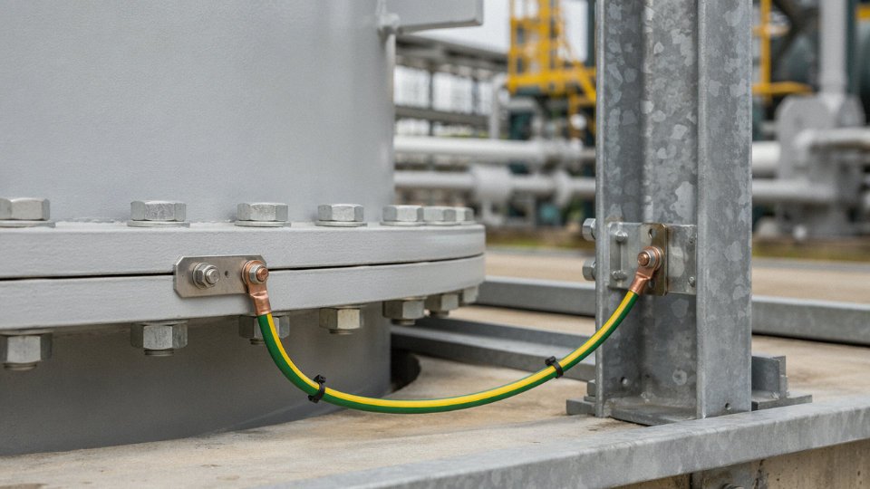
The polymer problem is less obvious but genuinely dangerous. PVC compound, HDPE, and cross-linkable polyethylene all build up static charge during extrusion — surface potentials of 10–50 kV are routinely measured on extruded profiles before they reach a cooling trough, depending on line speed, material formulation, and ambient humidity. At the low end, that charge attracts airborne polymer dust and carbon black particles onto the still-soft insulation surface, producing contamination defects that only show up during high-voltage spark testing or, worse, in the field. At the upper end, near any solvent-based release agent or a drum of mold-release compound, it becomes an ignition risk. Anti-static bonding cables running from the extruder head to the building ground bus — with verified end-to-end resistance below 10 Ω, measured and logged at every maintenance interval — are not optional. In practice they get neglected. A good maintenance regime checks them quarterly.
Three Earthing Functions, Three Conductor Specifications
Protective earthing (PE) exists to clear fault current fast enough to trip the upstream protective device. IEC 60364-5-54 sets the sizing — typically 16 mm² copper minimum for most LV circuits in a factory environment, scaling up with the phase conductor cross-section. Green/yellow PVC-insulated stranded copper is the standard for fixed panel and trunking runs. For anything in direct earth contact or exposed to the damp concrete trenches common under production floors, tinned copper is worth the modest premium; bare aluminum in direct earth contact corrodes badly within a few years in most soil conditions and should simply be avoided for earthing conductors, regardless of what a budget-driven design spec might suggest.
Functional earthing for instrumentation is a separate discipline. The reference potential for a 4–20 mA loop or a Pt100 circuit needs a low-impedance, low-noise path to a dedicated clean earth electrode — physically separated from the main PE system where practical, connected at a single point. This is the source of the single-point versus multi-point earthing debate that experienced instrumentation engineers will recognize immediately. Below roughly 1 MHz — which covers every analogue signal in a cable plant — single-point (star) earthing prevents the ground loops that corrupt millivolt-level signals. Screens on analogue cables should be terminated at one end only, typically the control panel end, and left floating at the field instrument. For high-frequency digital fieldbus and Industrial Ethernet, multi-point earthing reduces shield impedance at the frequencies that matter, and isolated-screen cables with distributed shield grounding are correct practice.
Equipotential bonding conductors between machine frames need a minimum 4 mm² copper cross-section under IEC 60364-4-41, though many experienced plant engineers run 6 or 10 mm² as standard because the cost difference is negligible and the installation lasts decades.
Lightning Protection in Large Production Buildings
A cable manufacturing building — often 80–150 m long, 20–30 m wide, with roof-mounted HVAC units and cable drum storage yards nearby — presents a meaningful lightning exposure. IEC 62305-3 requires down-conductors of minimum 50 mm² copper or 100 mm² aluminum, with calculated separation distances from internal wiring to prevent side-flash. In practice, the separation distance calculation gets skipped on older plants or during extensions, which is how you end up with a lightning strike that destroys a PLC rack 15 metres from the down-conductor. Surge protection devices to IEC 61643-11 Class I+II on every incoming power feed and data line are the last line of defense — not the first.
Aluminum earthing conductors in direct earth contact are a long-term corrosion risk and should be avoided regardless of initial cost savings.True
Aluminum forms aluminum hydroxide in moist soil conditions, progressively increasing contact resistance and compromising fault current clearance — IEC 60364-5-54 specifically cautions against aluminum in direct earth contact applications.
The earthing system in a cable plant is essentially the immune system of the entire electrical installation. It rarely fails dramatically. It degrades gradually — a loose bond here, a corroded trench conductor there — and the symptoms show up as unexplained quality variation, random VFD faults, and signal drift that no one connects to the root cause until something finally trips hard.
How Jinda Specifies, Sources, and Quality-Assures the Cables Used in Its Own Facilities
There’s a particular discipline that comes from being both the manufacturer and the end-user. When Jinda’s engineering team sits down to specify cables for a new production line or facility upgrade, they aren’t relying on a supplier’s datasheet and hoping for the best. They write a Technical Procurement Specification — a TPS — for every cable category on the project: MV feeders, LV motor circuits, control and instrumentation, LSZH safety circuits, flexible reeling cables, and earthing conductors alike.
Each TPS is structured to eliminate ambiguity at the point of order. It calls out conductor material and flexibility class per IEC 60228 (Class 2 for fixed wiring, Class 5 or 6 for anything that moves), specifies the insulation system by designation rather than trade name, defines shielding construction and coverage percentage, sets armor type and nominal thickness, states the outer sheath color and compound, and fixes temperature rating — typically 90°C continuous for XLPE circuits near extrusion equipment, sometimes 105°C for cables running through the vulcanization zone. Flame performance requirements reference IEC 60332-3-24 as a floor, with LSZH sheath and IEC 60754 halogen emission limits applied wherever cable bunches near polymer storage or finished reel inventory. Dimensional tolerances on conductor diameter and insulation eccentricity are tighter than the relevant GB/T standard defaults, because Jinda’s own production experience tells you exactly how much tolerance stack-up causes termination problems in confined panel spaces.
The Vendor Qualification Paradox
Sourcing cables externally when you operate five cable production bases creates an unusual situation. Jinda’s incoming inspection team tests against the same IEC references used for outgoing product — and uses largely the same bench equipment. Conductor resistance is measured per IEC 60228 at 20°C-corrected values, not taken on faith from a test certificate. Insulation resistance is verified per IEC 60502-1. Every reel goes through a spark test per IEC 60332 on a sample length. For MV cables above 6 kV, partial discharge testing per IEC 60885-3 is performed at 1.5 U₀, with a PD extinction level typically set below 10 pC — a threshold that would disqualify a surprising proportion of commodity-grade product.
Cable manufacturers that also perform incoming electrical testing on purchased cables consistently find a higher defect rate than their suppliers' certificates suggest.True
Incoming inspection by technically capable buyers regularly uncovers conductor resistance deviations, eccentricity failures, and spark-test faults that passed supplier self-certification — a well-documented quality gap in commodity cable supply chains.
In practice, fewer external vendors pass Jinda’s qualification round than initially expect to. That’s not a procurement strategy; it’s just what happens when you know exactly what a compliant cable should look like.
After Installation: FAT as Standard Practice
Commissioning a new production line includes a formal cable FAT. LV circuits get a 1 kV DC megger test with insulation resistance logged and compared against the benchmark value from the day of installation — that baseline record matters enormously for trending. MV circuits are hi-pot tested at 2U₀ AC for five minutes. Continuity and phase rotation checks are documented before any equipment is energized. Shield integrity on instrumentation and VFD feed cables is measured end-to-end, because a single nick in a shield during pulling can ruin EMC performance across an entire control cabinet.
Routing Documentation and Lifecycle Tracking
Every installed cable carries a barcode tag at roughly 5 m intervals on runs longer than 20 m. As-built schedules and route drawings are maintained in AutoCAD or EPLAN, updated after any modification — not reconstructed from memory two years later when someone needs to pull an additional circuit. Reeling and crane cables are logged for cumulative bending cycles and scheduled for predictive replacement at around 80% of the manufacturer’s stated flex life, which varies considerably depending on bend radius, cycle rate, and ambient temperature. Annual thermal imaging surveys on terminations catch resistance creep at lugged connections before it becomes a fault. Insulation resistance trending on motor feeds — recorded quarterly on critical drives — has, in more than one case, caught a degrading circuit weeks before it would have tripped a line.
Why This Internal Rigor Translates Directly to Customer Support
The engineers writing Jinda’s internal TPS documents are the same engineers who author the Technical Data Sheets, support application engineering queries, and travel to customer sites for FAT assistance. That’s not a marketing claim — it’s a structural reality of how the technical team is organized. When a procurement manager at a substation contractor asks whether a specific cable construction will pass a particular partial discharge acceptance criterion, the answer comes from someone who has written that acceptance criterion into their own plant’s purchase orders. The internal discipline, in other words, is the external competence. Both are built from the same accumulated plant-floor experience.
Frequently Asked Questions: Cable Selection for Industrial and Manufacturing Environments
A cable factory is, in many ways, the harshest possible test environment for the products it makes. The questions below come up repeatedly in procurement conversations — from project engineers specifying a new motor control center to facility managers trying to understand why a cable that “meets spec on paper” failed at 18 months. The cable-plant context gives unusually concrete answers.
What is the difference between PVC and LSZH sheath cables, and when should I specify LSZH?
PVC sheath is cheaper, mechanically tougher, and handles UV and oil exposure well. The problem is combustion chemistry: burning PVC releases hydrogen chloride gas and dense black smoke. In a large open factory bay with high ceilings and roll-up doors, that may be manageable. In an enclosed test laboratory, a compounding room, a cable drum storage tunnel, or any space where personnel cannot evacuate within 90 seconds, it is not acceptable.
LSZH (low-smoke zero-halogen) compounds, qualified under IEC 60754-1/2 for halogen acid gas and IEC 61034-2 for smoke density, are the correct specification for those enclosed spaces. In Jinda’s own compounding areas — where polymer pellets, lubricants, and crosslinking agents sit alongside electrical equipment — LSZH is the standing internal standard, not an upgrade option. The cost premium runs roughly 15–30% over equivalent PVC cable, depending on cross-section and compound grade, but it is non-negotiable where occupant safety or sensitive electronics are at risk. Smoke alone can destroy a control panel; HCl damage to copper bus bars can take weeks to manifest.
Can I use aluminum conductors instead of copper to save cost?
Yes, with important conditions. For fixed installations at 25 mm² and above — main feeder runs, riser cables, busbar trunking tap-offs — aluminum is a legitimate and commercially sensible choice, provided you use bimetallic compression lugs at every termination and follow the torque specifications without exception. Aluminum oxide forms fast, and a loose or undertorqued lug on an aluminum conductor will overheat. Below 25 mm², aluminum becomes brittle and difficult to terminate reliably; copper is the only practical option.
For motor feeds, VFD supply cables, or anything with even occasional flexing, copper is mandatory. Aluminum work-hardens and cracks at small bend radii. The cost saving on a 50-meter motor feed cable does not offset a single unplanned motor outage.
Aluminum conductors are suitable for all industrial power cable applications if the cross-section is large enough.False
Aluminum is appropriate only for fixed, non-flexing installations above 25 mm², with correct bimetallic terminations. It is not suitable for motor feeds, VFD cables, flexible connections, or any application below 25 mm² due to brittleness and termination reliability concerns.
How do I select cable cross-section for a long factory run?
Three checks, in order. Size first for current-carrying capacity using IEC 60364-5-52 tables, adjusted for your actual installation method — trefoil touching in a tray derates significantly versus single cables in free air — and apply grouping factors if multiple cables share the same route. Then verify that voltage drop over the run length stays within your project limit, typically 3–5% for motor circuits. Finally, confirm the conductor can withstand the prospective short-circuit current for the fault clearance time of your upstream protective device.
The governing cross-section is whichever of those three checks produces the largest result. In practice, long runs in large factories — 200 meters or more from the MCC to a draw bench — are often voltage-drop limited, not ampacity limited. Skipping that second check is a surprisingly common design error that shows up as nuisance tripping or sluggish motor starting.
What standards should I specify for cables going to different regions?
IEC 60502 (power cables up to 30 kV), IEC 60227, and IEC 60245 cover the majority of projects across Asia, the Middle East, Africa, and continental Europe. UK and parts of the Commonwealth still reference BS EN standards, which are largely harmonized with IEC but have specific British Standards markings and test requirements. North American projects require UL or CSA certification — a different approval pathway entirely, not just a label swap.
Jinda holds certifications across these major markets and can produce to project-specific standards, including dual-standard cables where a project requires both IEC and a regional mark simultaneously. Specifying the standard at the inquiry stage, not after order placement, avoids the most common delays.
How does Jinda support large international procurement projects with lead time certainty?
Five production bases across China, 470,000 m² of manufacturing floor, and over 1,000 employees give Jinda genuine production depth — not just catalog capacity. For large projects, Jinda maintains buffer stocks of copper rod, aluminum, and XLPE compound to absorb market supply volatility, which matters considerably when a project’s cable schedule is tied to a grid energization date.
A dedicated project manager handles production scheduling, third-party inspection coordination (SGS, Bureau Veritas, or client-nominated inspectors), and the documentation package required for Letters of Credit — test reports, factory acceptance test certificates, country-of-origin declarations, packing lists cross-referenced to drum numbers. These are the things that cause payment delays when they are missing or inconsistent. Having handled both sides of that process — manufacturing and project supply — Jinda’s project teams understand what a procurement manager needs from a documentation package versus what a site engineer needs on delivery day.
What minimum bending radius must I respect during cable installation?
For armored power cables during installation, the minimum static bending radius is typically 8–15× the cable’s overall diameter; the exact figure depends on the number of cores, armor type, and whether the cable is shielded. The manufacturer’s datasheet governs — not a general rule of thumb. During cable pulling through conduit or cable tray, temporary bending at the sheave blocks must also stay within this limit.
For flexible reeling and trailing cables in dynamic service, the dynamic minimum bending radius drops to roughly 4–7.5× OD, but the cable must be specifically designed for that duty — finely stranded conductors, flexible insulation compound, anti-torsion armor lay. Fitting a standard fixed-wiring cable onto a reeling drum and assuming it will survive because the static radius is “within spec” is a common and expensive mistake. The failure mode — individual strand fractures and micro-cracks in the insulation — often won’t show up on an insulation resistance test until the cable has already been in service long enough to cause a nuisance fault at the worst possible moment.