Specify the wrong cable for a power circuit and the consequences stack up fast: insulation that softens and tracks under load, conductors that run hot enough to accelerate oxidation at every termination, protective devices that never quite trip at the right time because the impedance doesn’t match the design assumption. A single undersized or wrong-insulation cable in a distribution run can sit quietly for months before it causes a fault — and when it does, you’re looking at unplanned downtime, scrapped product on a line that lost power mid-cycle, potential fire investigation, and a rewiring job that costs five to ten times what the correct cable would have cost at the outset.
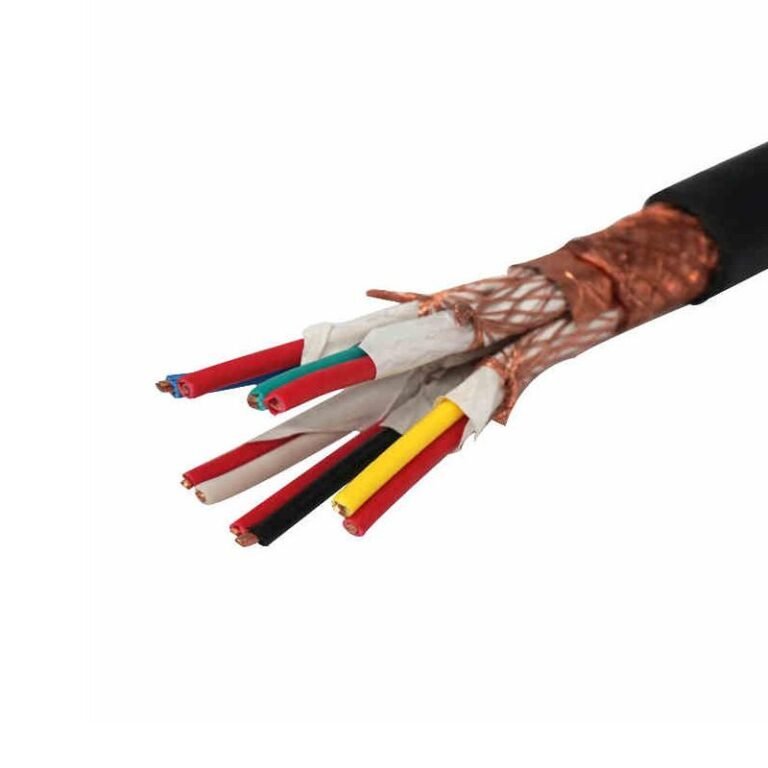
Power cables are purpose-built conductors — typically copper or aluminium — covered with a rated insulation system (most commonly XLPE or PVC) and designed to carry electrical energy at a defined voltage class, from low-voltage distribution at up to 1 kV through medium-voltage feeders in the 1–35 kV range, up to high-voltage transmission lines. The right cable depends on voltage class, current-carrying requirement, installation environment, and whether the circuit is fixed wiring, buried, or exposed to mechanical stress or chemicals.
What makes the selection genuinely complicated is how many variables interact at once — and how differently the same cable performs depending on whether it’s in a conduit in a 45°C tropical plant room, direct-buried under a road, or clipped to a tray in an air-conditioned switchroom. Low-voltage cables alone account for roughly 60–65% of global cable consumption by volume, which tells you something about how much of the world’s electrical infrastructure lives at that end of the spectrum — and how much money is either saved or wasted depending on whether the procurement spec was written by someone who actually understood the application.
Voltage Classes Explained: Low, Medium, and High Voltage Power Cables and Where Each Is Used
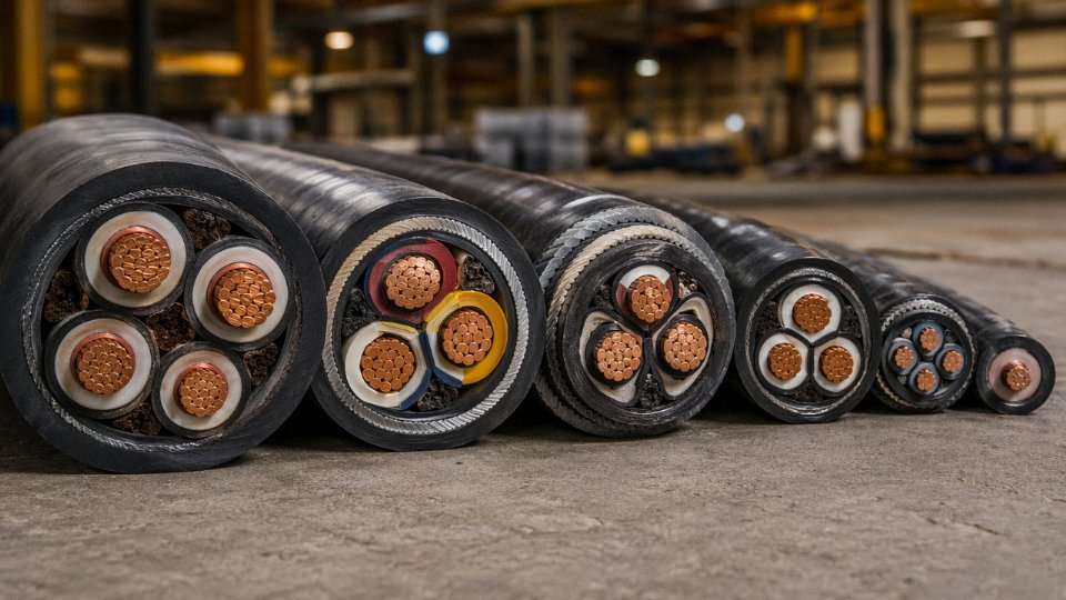
Voltage class is the single most consequential specification you lock in before anything else — before conductor size, before insulation material, before armour type. Get it wrong and you’re either massively over-engineered (and over-budget) or you’re running a cable that will fail under electrical stress within months. The taxonomy isn’t complicated, but the design logic behind each tier is worth understanding properly.
Low-Voltage Cables: Up to 1 kV
This is the workhorse tier. LV cables — rated up to 1 kV — account for roughly 60–65% of global cable consumption by volume, and that figure makes sense when you think about how many kilometres of wiring sit inside a single industrial plant, let alone a housing development or a solar farm.
Applications are broad almost to the point of mundane: building wiring, motor feeds from distribution boards, control-room power runs, appliance connections, and increasingly, DC string wiring in photovoltaic arrays. Common constructions you’ll actually encounter on a plant floor include NYY (PVC-insulated, PVC-sheathed, suitable for direct burial in many cases), YJV (XLPE-insulated, the modern preference where heat load or future upgrade is a concern), and SWA armoured variants where mechanical protection matters — cable trays in a food-processing facility, for instance, or buried runs across a busy yard.
At this voltage level, insulation is relatively thin. The electrical stress on the dielectric is low enough that basic PVC or XLPE works without elaborate screen geometry. Cost per metre is correspondingly low, though that doesn’t mean procurement should be sloppy — conductor purity, concentricity, and sheath thickness tolerances all affect long-term reliability in ways that only show up years later.
Medium-Voltage Cables: 1–35 kV
Step up to MV and the design philosophy changes noticeably. These cables feed utility distribution feeders, wind-farm collection grids, industrial campus substations, and large process-plant main incomer circuits. The voltage is high enough that electric field distribution at the conductor surface and at the insulation screen becomes critical.
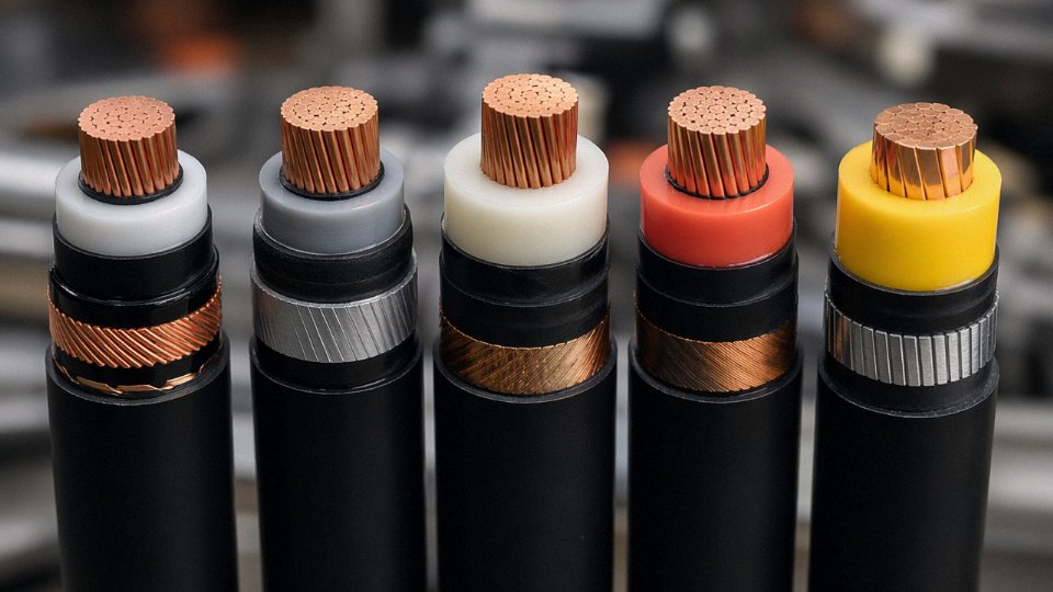
This is where semi-conductive stress-control layers earn their place. A metallic screen — typically copper tape, copper wire, or a combination — surrounds the insulation and equalises the radial electric field. Without it, field concentration at any geometric irregularity can initiate partial discharge and, over time, treeing failure. Specifying an MV cable without a proper metallic screen and inner semi-conductive layer is, in practice, not specifying an MV cable at all.
XLPE has become the dominant insulation at this tier, largely displacing PVC above roughly 3–4 kV during the 1990s. Its 90°C maximum continuous conductor temperature versus 70°C for standard PVC means meaningful extra ampacity in the same conductor cross-section — useful when you’re trying to squeeze more current through an existing duct bank without digging.
High-Voltage and Extra-High-Voltage Cables: 66 kV–500 kV
HV and EHV cables are a different engineering world. These carry bulk transmission power under city centres, connect offshore wind collections to onshore grids via HVDC links, and tie together national grid nodes where overhead line routing is impractical. The insulation wall is thick — sometimes 20–30 mm or more depending on voltage and cable design — and the manufacturing tolerances are correspondingly tight. Void content, concentricity, and compound purity are monitored continuously because a single defect at 220 kV will fail, not degrade gracefully.
Legacy oil-filled (pressurised oil-paper) designs still exist in older urban networks and require active pressure-monitoring systems, oil reservoirs, and dedicated maintenance regimes. Modern installations use dry-cure XLPE exclusively. The difference in operational overhead is substantial.
XLPE insulation supports a maximum continuous conductor temperature of 90°C, compared to 70°C for standard PVC, making it the preferred insulation for medium- and high-voltage power cable applications.True
This is consistent with IEC 60502 and IEC 60228 design parameters and is a well-established thermal rating difference between the two insulation materials in power cable engineering.
Voltage Class Reference Table
| Voltage Class | Typical Voltage Range | Primary Applications | Common Insulation | Typical Standard |
|---|---|---|---|---|
| Low Voltage (LV) | Up to 1 kV | Building wiring, plant distribution, PV string wiring | PVC, XLPE | IEC 60502-1 |
| Medium Voltage (MV) | 1 kV – 35 kV | Utility feeders, wind-farm collection, industrial campuses | XLPE (with semi-con screens) | IEC 60502-2 |
| High Voltage (HV) | 36 kV – 150 kV | Regional transmission, large substation interconnects | XLPE | IEC 60840 |
| Extra-High Voltage (EHV) | 150 kV – 500 kV | Bulk transmission, HVDC links, urban underground grids | XLPE (dry-cure) | IEC 62067 |
Why Voltage Class Drives Everything Downstream
Insulation thickness scales with voltage class in a way that directly multiplies cost per metre — not linearly, because material cost compounds with increased conductor screen, insulation screen, and metallic screen complexity as you move up. An MV cable at 11 kV can cost three to five times more per metre than a comparable-conductor LV cable, depending on screen design, armour, and sheath specification. HV cables can run an order of magnitude higher again.
The practical consequence: a specifier who hasn’t confirmed the operating voltage — including any future upgrade scenarios — before issuing an RFQ is wasting everyone’s time. Voltage class determines insulation thickness, screen design, joint and termination requirements, and the manufacturing process itself. Everything else follows from it.
Core Insulation Materials Compared: PVC, XLPE, EPR, and LSZH for Power Applications
Pick the wrong insulation material and you’re not just looking at a warranty problem — you’re looking at premature failure, a fire liability, or a cable pull that has to be redone in three years because the jacket cracked in the cold. The four materials that dominate power cable insulation and sheathing each have a distinct chemical logic behind their performance envelope, and understanding that logic is what separates a defensible specification from a guess.
PVC — Workhorse of Low-Voltage Wiring, With a Real Ceiling
Polyvinyl chloride is cheap, flexible at room temperature, easy to extrude, and mechanically tough enough for most building and light industrial wiring. For standard LV distribution — factory floor lighting circuits, panel feeds, residential service entrances — it does the job reliably. The continuous conductor temperature limit sits at 70°C for standard grades, which is adequate for most fixed installations if you haven’t undersized the conductor.
The problem is fire behavior. PVC contains chlorine by definition, and when it burns it releases hydrogen chloride gas — a dense, corrosive, and acutely toxic fume. Hydrogen chloride concentrations above roughly 50 ppm cause severe respiratory damage. In a confined space like a tunnel, a hospital basement cable duct, or a shopping center plantroom, that’s not an acceptable risk. Most current European fire regulations (CPR, IEC 60332 series) and equivalents in other markets effectively prohibit PVC-sheathed cables in those environments for exactly this reason. If a project specification lists IEC 60332-3 category C or better, PVC is usually out.
XLPE — The Default Choice Above LV for Good Reason
Cross-linked polyethylene replaced PVC in medium- and high-voltage applications through the 1990s and has stayed dominant since. The cross-linking process — whether done with peroxide, silane, or electron beam — converts the thermoplastic polyethylene chain into a three-dimensional network that resists thermal deformation at temperatures where standard PE would soften. That gives XLPE a continuous conductor rating of 90°C and a short-circuit withstand of around 250°C, a substantial margin over PVC.
XLPE insulation provides a higher maximum continuous conductor temperature than standard PVC, allowing more current through the same conductor cross-section.True
Standard PVC-insulated cables are rated to 70°C conductor temperature; XLPE is rated to 90°C continuous. At identical conductor size and ambient conditions, the higher thermal rating translates to a higher permissible current per IEC 60502 and related standards.
Dielectric losses in XLPE are also meaningfully lower than in EPR — the loss tangent (tan δ) for XLPE typically runs in the range of 0.0002–0.0004 versus 0.003–0.008 for EPR, depending on compound and voltage stress. Over a 20 km underground transmission circuit, that difference adds up to real energy cost. XLPE also absorbs very little moisture, which matters for buried cable longevity — water treeing in older XLPE formulations was a recognized failure mode, but modern tree-retardant XLPE (TR-XLPE) compounds have substantially reduced that concern.
EPR — When the Environment Fights Back
Ethylene propylene rubber isn’t trying to compete with XLPE on dielectric losses. It wins on flexibility and environmental resilience. EPR remains pliable down to around -50°C, which makes it the practical choice for mining trailing cables, Arctic installations, offshore platform feeders, and any application where the cable is repeatedly flexed or dragged across surfaces. The rubber matrix tolerates ozone, UV, and wet conditions without the crack propagation you’d see in aged XLPE under the same mechanical abuse.
Submarine cables and variable-speed drive connections in harsh environments — the kind of application where you want a cable that bends thousands of times without work-hardening — are where EPR justifies its cost premium over XLPE. In a typical underground urban grid, EPR doesn’t add enough value. In a North Sea cable tray or a quarry dragline, it’s the right call.
LSZH — Fire Performance at a Real Mechanical Trade-Off
Low-smoke zero-halogen compounds — sometimes called LS0H or LSOH depending on the standard — use halogen-free flame retardants (typically aluminum trihydroxide or magnesium hydroxide fillers) to achieve fire performance without the toxic gas problem of PVC. In a metro tunnel or airport terminal, LSZH sheathing buys critical evacuation time: smoke opacity stays low, and the combustion gases, while not harmless, are far less acutely toxic than HCl.
The trade-off is mechanical. LSZH compounds are generally stiffer than PVC at low temperatures and have lower abrasion resistance — a meaningful issue in cable trays with rough edges or in conduit installations where the cable is pulled against other cables. Specifying LSZH in an outdoor cable tray in a cold climate without checking the -15°C or -20°C installation temperature rating has caused cracked sheaths on more than one project. It’s worth confirming the cold-bend test temperature in the product datasheet before signing off on a spec in northern Europe or Canada.
Side-by-Side Properties at a Glance
| Material | Max Continuous Temp (°C) | Dielectric Strength (kV/mm, typical range) | Halogen-Free | Typical Voltage Tier | Relative Cost Index |
|---|---|---|---|---|---|
| PVC | 70 | 10–20 | No | LV (≤1 kV) | Low (1.0×) |
| XLPE | 90 | 20–35 | Yes | LV / MV / HV | Medium (1.3–1.6×) |
| EPR | 90 | 15–25 | Yes (most grades) | LV / MV / submarine | Medium-high (1.5–2.0×) |
| LSZH | 70–90 (grade-dependent) | 15–25 | Yes | LV / MV | Medium (1.2–1.8×) |
Cost index figures are relative to commodity PVC-insulated LV cable and shift with compound pricing and order volume — EPR in particular moves with ethylene propylene monomer markets.
Jinda’s production lines cover all four insulation families, which in practice means a project with mixed cable types — say, XLPE-insulated MV feeders alongside LSZH-sheathed LV distribution cables in a public transit depot — can be sourced from a single supplier with consistent quality documentation. That matters more than it sounds when you’re managing ITP records across a large installation.
Conductor Materials and Cross-Section Sizing: Copper vs. Aluminium and How to Calculate the Right AWG or mm²
The conductor is where the physics happens. Everything else — insulation grade, sheath material, armour type — is protection and containment. Get the conductor material or cross-section wrong and you’re paying for it every hour the cable carries load, sometimes for decades.
Copper vs. Aluminium: The Real Trade-Off
Copper’s resistivity runs around 1.72 µΩ·cm at 20°C; aluminium sits at roughly 2.82 µΩ·cm. That gap translates to copper carrying about 58% more current through the same cross-sectional area, which is why a 70 mm² copper conductor and a 95–120 mm² aluminium conductor are often interchangeable in feeder designs. Aluminium is also about 30% of copper’s weight per metre, and in bulk procurement — especially for large-bore cables — the price difference per ampere-metre of capacity is typically 40–50% in aluminium’s favour, though that spread moves with commodity markets and can narrow when aluminium alloy prices spike.
So when does aluminium actually win? Underground feeders above roughly 120 mm², overhead distribution lines, and utility-scale solar or wind collection circuits where you’re pulling kilometres of cable across a site. On a 500 kW solar farm string circuit running several hundred metres, switching from copper to aluminium XLPE cable can shave a meaningful chunk off the BOM cost without changing the thermal design — provided the installation crew knows what they’re doing at the terminations.
That last clause matters. Aluminium oxidises fast. The oxide layer is both resistive and hard, and if you’re using standard copper-spec compression lugs without bi-metal transition or anti-oxidant compound (Noalox or equivalent), you’ll see hot joints within a year or two, sometimes sooner in humid environments. This is the single biggest reason aluminium gets a bad reputation on industrial sites: not the material itself, but termination practice. Copper forgives sloppy terminations far more readily.
Copper wins clearly in control panels, flexible cords, marine and offshore cables, and anywhere the cable sees repeated bending or frequent re-termination. The oxide issue disappears, bend radius is tighter for the same ampacity, and the smaller physical diameter often matters in congested cable trays.
Sizing by IEC 60287: A Worked Example
The IEC 60287 methodology starts with your design current, then applies derating factors before you pick a cross-section — not the other way around. The sequence: calculate load current → identify ambient temperature correction factor (k₁) → grouping/bunching factor (k₂) → burial depth factor for underground (k₃) → divide design current by the product of all derating factors → select the next standard cross-section up.
Say you need a 400 A feeder, single three-core cable, XLPE insulated, installed in free air at 40°C ambient with no grouping. IEC 60502-1 base ratings assume 30°C; at 40°C the temperature correction factor for XLPE (90°C rated) is roughly 0.91. So effective required rating = 400 ÷ 0.91 ≈ 440 A. A 185 mm² copper conductor in free air typically carries around 430–470 A depending on installation detail — so 185 mm² is your selection. If you’d skipped the derating and just looked up 400 A, you might have landed on 150 mm², which runs hot and shortens insulation life noticeably over a 25-year asset life.
Quick-Reference Cross-Section Table
| Nominal mm² | Cu Rating, Free Air (A) | Al Rating, Free Air (A) | Voltage Drop, 100 m at Rated Current (V) — Cu |
|---|---|---|---|
| 35 | 170–190 | 130–150 | ~9–11 |
| 70 | 255–285 | 195–220 | ~7–9 |
| 120 | 340–375 | 265–295 | ~5–7 |
| 185 | 430–470 | 335–370 | ~4–5 |
| 240 | 510–550 | 395–435 | ~3–4 |
Ratings depend on installation method, ambient temperature, and grouping — treat these as orientation values, not design sign-off figures.
The Lifecycle Economics of Going Up One Size
Upsizing cross-section is one of the few cable decisions that pays back. I²R losses scale with the inverse of cross-section; replacing a 10 mm² feeder with 16 mm² reduces resistance by roughly 37%, cutting resistive losses by the same proportion. On a circuit running at near-rated current for most of its life — think a pump motor feeder or a continuous process line — that loss reduction over 20 years often covers the incremental cable cost several times over, especially as energy prices have moved. The calculation takes maybe 20 minutes and is worth doing for any feeder above about 50 A.
Aluminium conductors require anti-oxidant compound and compatible lugs at all termination points to prevent resistive overheatingTrue
Aluminium forms a hard, resistive oxide layer rapidly on exposed surfaces. Without anti-oxidant compound and bi-metal or aluminium-rated compression lugs, contact resistance rises at terminals, generating localised heat that can lead to insulation damage, loose connections, or fire risk over time. This is well-established in IEC and NEC installation practice.
Armoured vs. Unarmoured Power Cables: Mechanical Protection Specifications for Underground, Tray, and Direct-Burial Installations
The single most common procurement mistake I see on multi-route projects is specifying the same cable construction for every segment of a run — pulling unarmoured cable through a duct bank, then continuing that same spec into a direct-burial section because someone assumed the duct protected everything. It doesn’t, and a mechanical fault three years later in the buried segment is an expensive lesson.
Armour selection is really installation-method selection. The cable doesn’t know what voltage it’s carrying; it only knows what the ground, the pulling gear, and the ambient chemistry are doing to its outer layers.
Steel Wire Armour, Steel Tape Armour, and Aluminium Wire Armour — What Each Is Actually Designed For
Steel wire armour (SWA) is the workhorse. Helically applied galvanised steel wires — typically 0.8 mm to 3.15 mm diameter depending on cable overall diameter — give you both radial crush resistance and genuine axial tensile strength. That combination matters for direct burial in rocky or disturbed ground, for cables pulled through long conduit runs, and wherever a backhoe might someday wander. IEC 60502-1/-2 and BS 5467 govern construction and test requirements; if a supplier can’t cite those standards on their test certificate, that’s a red flag.
Steel tape armour (STA) is a different animal. Two overlapping steel tapes applied in a short helix give good radial protection but essentially no tensile strength. STA suits straight underground routes in stable, fine-grained soil where the load is purely compressive — think a cable trench through a manicured industrial park, not a route crossing a drainage ditch with seasonal ground movement. Trying to pull STA cable around bends or through a long duct will buckle the tape at stress concentrations and eventually breach the bedding underneath.
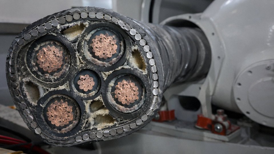
Aluminium wire armour (AWA) exists because of a real electromagnetic problem. Run steel wire armour on a single-core AC cable and the alternating magnetic field from the conductor induces circulating currents in the closed steel loop. Those eddy current losses can add anywhere from 5% to over 20% to cable losses depending on conductor size and current magnitude — a serious thermal derating penalty on high-current circuits. AWA breaks that loop electrically; aluminium’s lower permeability suppresses eddy currents to negligible levels. For single-core cables in 11 kV and above distribution, AWA is essentially mandatory on AC systems unless you’re using trefoil-grouped cables with a specific bonding scheme.
The Inner Sheath Does More Work Than Most Specs Acknowledge
Between the insulation cores and the armour sits the inner sheath — sometimes called bedding in older British terminology. Its job is twofold: it cushions the armour wires so they don’t abrade directly against insulation during installation, and it seals out moisture that would cause galvanic corrosion between the steel armour and any metallic screen or conductor beneath it. Skimping on inner sheath thickness to reduce cable diameter is a real temptation for budget builds. In practice, a degraded inner sheath on a buried cable usually isn’t discovered until the armour wires have already corroded through in a wet section, by which point you’re looking at a full cable replacement rather than a repair.
Installation Method Drives the Specification
| Installation Context | Minimum Armour Requirement | Outer Sheath | Notes |
|---|---|---|---|
| Cable tray / ladder, indoors | None (armour optional) | LSZH if occupied building | Armour adds weight; may be omitted if tray provides support |
| Concrete duct bank | SWA or STA acceptable | PVC or PE | Duct provides crush protection; tensile still matters for long pulls |
| Direct burial, stable soil | SWA minimum | PVC, consider PE in wet ground | Add sand bedding and warning tiles in traffic/HV zones |
| Direct burial, rocky / congested | SWA with increased wire diameter | PE preferred | Consider concrete encasement at road crossings |
| Horizontal directional drilling (HDD) | High-tensile SWA | PE outer sheath — must withstand pulling head loads | Calculate maximum tensile load; confirm with cable manufacturer |
| Marine / submarine | Double SWA, bitumen-saturated jute or polypropylene serving | Bitumen/PP outer | Outer serving resists marine organisms and anchoring damage |
Armour Grounding on Single-Core AC Cables — Get This Wrong and You Derate the Cable
Steel wire armour on single-core AC cables bonded at both ends will develop circulating currents that cause continuous thermal losses and reduce current-carrying capacity.True
When armour forms a closed loop around a single AC conductor, the alternating flux induces a voltage along the armour. Bonding both ends allows current to circulate, generating resistive heat. IEC 60502 and engineering handbooks consistently document this derating effect; the fix is single-point bonding or cross-bonding on long routes.
On runs under roughly 500 m, single-point bonding — earthing the armour at one end only — keeps circulating current to negligible levels. Longer routes in transmission or large-scale distribution work need cross-bonding, where the cable is divided into three equal minor sections and the sheaths transposed, cancelling induced voltages. Both approaches require careful engineering of the earthing arrangement; a floating armour at the unearthed end needs a surge voltage limiter to handle lightning or switching transients. This is not a detail to leave to the installation contractor without explicit specification.
The decision logic is straightforward once you’ve mapped the route: buried means armoured, curved routes under tension means SWA over STA, single-core AC means AWA, and anything marine means double SWA with bitumen serving. The mistakes happen when procurement treats armour as an optional upgrade rather than an installation-method requirement baked into the cable spec from day one.
Specialised Power Cables for Renewable Energy, Mining, Shipbuilding, and Fire-Resistant Applications
Standard utility cable solves most problems. But once you step into a solar field, a longwall mine, a drillship, or a fire-pump room, the off-the-shelf product fails — sometimes quietly through premature degradation, sometimes catastrophically. Each of these environments imposes a combination of stresses that general-purpose cable simply wasn’t designed to survive for 20-plus years.
Solar PV DC Cables
The rating people usually focus on is voltage — 1.5 kV DC under EN 50618 / TÜV 2 Pfg 1169. That matters, but it’s not the whole story. UV exposure, ozone cracking, and thermal cycling between roughly −40°C and +90°C conductor temperature are what actually kill PV cables early. Dual-layer insulation and a tinned copper conductor are baseline requirements, not premium options.
Tracker-mounted arrays make things harder. A single-axis tracker rotates through roughly 60° every day, which means the inter-row homerun cables flex somewhere between 8,000 and 10,000 cycles over a 25-year design life, depending on latitude and controller logic. Specify a cable without adequate flex rating for that arc and you’ll see insulation cracking at the conduit entry points within five to eight years — long before the inverter warranty expires. In practice, most EPC contractors have learned this the hard way on early utility-scale projects.
Wind Energy Torsion Cables
The nacelle-to-tower cable loop is one of the more demanding flex applications in any industry. IEC 61400 sets the framework, but the real spec burden falls on the cable: ±180° twist per metre, over millions of cycles across a turbine’s operational life. EPR insulation handles the flexibility and low-temperature performance; a polyurethane outer sheath handles the abrasion against the tower internals and cable tray edges that accumulates over years of yaw movement. Ordinary SWA armoured cable used here — it does happen — will fatigue-fracture the armour wires within a few years and eventually breach the conductors.
Mining Trailing and Conveyor Cables
Heavy trailing cables for continuous miners and shuttle cars need to survive being dragged across rock, run over by rubber-tyred vehicles, and kinked at the cable reel. Chloroprene (neoprene) and CSP (chlorosulfonated polyethylene) sheaths are the standard answers — they resist cuts and abrasion far better than PVC and don’t become brittle in cold headings. IEC 60502 and AS/NZS 1802 both apply depending on the jurisdiction; in gassy seams, IEC 60332-3 flame-retardant performance is not optional, it’s a legal requirement.
Belt-conveyor power cables add a different problem: continuous low-amplitude flex at the take-up pulley, combined with coal dust and occasional water ingress. Specifying the wrong sheath hardness is a genuine operational trap — too soft and it abrades through; too hard and it cracks at flex points.
Shipboard and Offshore Cables
IEC 60092 is the governing series, and the requirements stack up quickly: halogen-free insulation, mud- and oil-resistant outer sheath, and in most modern vessel electrical systems, individual or collective screening to control EMI from the variable-frequency drives running thrusters, pumps, and HVAC compressors. An unscreened cable run near a VFD on a drillship can corrupt instrumentation signals badly enough to trigger spurious shutdowns. That’s a costly lesson when the vessel is on day-rate.
Fire-Resistant and Fire-Survival Cables
Mineral insulated (MI/MICC) cables can maintain circuit integrity at 950°C for 180 minutes under IEC 60331 testing.True
IEC 60331-21/25 defines fire resistance tests at up to 950°C; mineral insulated cables using MgO insulation routinely achieve the 180-minute circuit integrity requirement, which is why they are mandated for fire pumps, emergency lighting feeders, and nuclear safe-shutdown circuits.
The limitation with MI cable is handling: it’s rigid, expensive per metre, and termination requires skilled labour and dry conditions. Mica-tape wrapped FR cables — where multiple layers of mica tape are applied over the conductor before the primary insulation goes on — give you broadly similar fire performance with meaningfully better flexibility. They’re the practical choice for complex routing in plant rooms and marine escape-route lighting circuits where you can’t pull rigid copper tube around every bend.
For nuclear applications and certain offshore platform safety systems, circuit integrity requirements push toward 180-minute ratings; commercial building emergency lighting feeders often only require 60 or 90 minutes. Know your standard before you spec.
Jinda’s R&D centre maintains active qualification programs across EN 50618, IEC 60092, IEC 60331, and the relevant mining standards, which means customers running mixed-sector projects — a solar-plus-storage facility with a grid-tied substation and a backup generator room, for instance — can consolidate sourcing without juggling four different qualified suppliers.
Key International Standards and Certification Marks Every Buyer Must Verify Before Procurement
Standards exist to protect projects, not paperwork. A cable that ships without proper certification doesn’t just create a compliance headache — it can cause a failed type test on a commissioned substation, a rejected shipment at customs, or worse, a fire in a cable tray that nobody can explain until the incident report traces it back to insulation that never actually met the declared specification.
How the IEC Standards Chain Together
The IEC framework is hierarchical, and understanding how the documents link is genuinely useful rather than just box-ticking.
IEC 60228 is where everything starts — it defines conductor classes (Class 1 solid, Class 2 stranded, Class 5 flexible, and so on) and the resistance limits each class must meet. If the conductor doesn’t comply here, every downstream current-rating calculation is built on a lie. IEC 60287 then provides the methodology to calculate continuous current-carrying capacity based on conductor resistance, insulation thermal resistivity, installation conditions, and ambient temperature — engineers doing route designs rely on this document heavily, and a cable with a falsified conductor cross-section will underperform every result that came out of that calculation.
IEC 60502 covers extruded solid dielectric insulated power cables from 1 kV up to 30 kV, and it splits into Part 1 (up to 3 kV) and Part 2 (6–30 kV). This is the workhorse standard for the vast majority of industrial, infrastructure, and distribution projects. Above 30 kV you move to IEC 60840 (up to 150 kV), and above 150 kV you’re in IEC 62067 territory for extra-high-voltage transmission cables where type testing alone involves months of electrical, thermal, and mechanical trials. These aren’t interchangeable — specifying IEC 60502 on a 132 kV project is a serious error.
Regional Equivalents Are Not Always Identical to IEC
BS 6346 and BS 5467 remain specified on many UK infrastructure projects and in former British-standard markets across the Middle East and East Africa. NF C 32-321 still appears in French utility tenders. VDE 0276 governs German practice. These national standards overlap substantially with IEC but diverge on test sequences, marking requirements, and sometimes insulation or sheath thickness minimums — a cable compliant to IEC 60502 is not automatically compliant to BS 5467, so check both if the tender requires both.
In North America, UL 44 (thermoset-insulated wires) and UL 83 (thermoplastic-insulated) are the reference documents, and the cable marking system, voltage designation conventions, and test protocols differ enough from IEC that direct substitution without review is risky. AS/NZS 5000 serves Australia and New Zealand and has its own sunlight-resistance and mechanical requirements that matter in outdoor and open-tray installations.
Certification Marks That Actually Mean Something on a Purchase Order
CE marking signals compliance with relevant EU directives but is self-declared — it carries weight, but it isn’t a substitute for third-party testing. The CPR (Construction Products Regulation) classification is more rigorous for cables installed in buildings: the Euroclass fire performance ratings (A1 through Fca) are based on actual reaction-to-fire tests, not declarations. For hazardous-area installations, ATEX certification (EU) and IECEx (international) are non-negotiable; a standard industrial cable in a Zone 1 explosive atmosphere is not just non-compliant, it’s a liability waiting to happen. Marine applications should carry Lloyd’s Register or Bureau Veritas type approval — offshore EPC contractors will typically reject any cable that can’t produce a valid TA certificate.
Red Flags That Show Up Before the Cable Even Gets Tested
Experienced procurement teams develop a short checklist they apply at goods receipt — or better, before the purchase order is placed.
Weigh the drum and calculate weight per metre. A declared 95 mm² copper conductor has a known mass; if the number is 8–12% light, the conductor cross-section is almost certainly under-size. This happens more than most buyers want to admit.
Check insulation thickness at the cut end against the standard minimum. IEC 60502-1 tabulates nominal and minimum values; a cable sitting 15% below minimum wall isn’t a borderline case, it’s a reject.
Drum markings must include voltage rating, standard number, conductor cross-section, manufacturer name, and year of manufacture. Missing or inconsistent marking is a low-effort fraud signal that requires no lab equipment to catch.
Third-party test reports older than roughly three years should prompt a conversation. Production processes change, and a 2019 test report for a drum manufactured in 2024 doesn’t tell you what you think it tells you.
What to Demand in Writing Before Any Shipment Is Accepted
Minimum documentation package: full technical datasheet, factory test report for the specific drum lot, and routine test certificates per IEC 60502-2 Clause 16 for MV cables (which covers conductor resistance, voltage test, insulation resistance, and partial discharge). For high-stakes projects, request the type test reports directly — not copies of copies.
Jinda holds ISO 9001 quality management certification, CE marking, and CCC certification, with type approvals covering its key export cable product ranges.True
These certifications are verifiable through the issuing bodies and are consistent with Jinda's published compliance documentation for international supply contracts.
Jinda supports factory audits and third-party inspection — SGS, Bureau Veritas, and similar agencies are regularly accommodated on the production floor. For large procurement contracts, that access matters: it means a buyer can send an inspector before shipment and verify drum markings, conductor weight, and test documentation against the actual production lot rather than relying entirely on paperwork. In practice, that’s the difference between a smooth project commissioning and a dispute over non-conforming goods six months into a build.
How to Read and Write a Complete Power Cable Specification for Global Procurement
Getting a cable specification wrong costs more than people expect. A mismatched voltage class means the insulation wall is undersized and the cable fails its commissioning test. An omitted conductor class creates a termination problem on site — solid Class 1 bar stock doesn’t behave like a stranded Class 2 conductor when you’re pulling lug crimps at 3 a.m. before a grid energisation deadline. Reordering from the wrong drum length adds unnecessary joints to a route, and every joint is a potential failure point. Writing a complete, unambiguous specification string takes about ten minutes. Fixing the consequences of a bad one can take weeks.
The Seven Fields That Define a Power Cable
Voltage rating (Uo/U). This is the first and most critical field. Uo is the rated voltage between any conductor and the screen or earth, while U is the rated voltage between conductors. A 0.6/1 kV cable has a 0.6 kV conductor-to-screen insulation design and a 1 kV phase-to-phase rating. Specifying a 0.6/1 kV cable on a system that actually runs 6/10 kV gives you a cable with an insulation wall that’s roughly one-quarter of what the application needs. This is not a marginal safety margin issue — it’s a dielectric breakdown waiting to happen.
Number of cores and cross-section. Write it as, for example, “3-core 185 mm²” or “3 × 185 + 1 × 95 mm² (3+1 formation).” Don’t assume the manufacturer will infer a neutral reduction. If you need a reduced neutral, state it.
Conductor material and IEC 60228 class. Copper or aluminium is the obvious choice, but class matters just as much in practice. Class 1 is solid, Class 2 is stranded (both intended for fixed installation), and Class 5 is fine-wire stranded for flexible applications. Omitting class is one of the most common spec errors in international procurement. Class 2 stranded is the default for most fixed power installations; Class 5 is what you need for panel wiring or trailing cable duty. Sending Class 1 solid conductor to a site expecting Class 2 creates real termination problems, especially at larger cross-sections above 95 mm².
Insulation material and temperature rating. XLPE at 90°C continuous is the standard choice for anything above roughly 1 kV, and increasingly common below it. PVC at 70°C still appears in low-voltage building wiring and some tray installations where cost is the dominant driver. EPR runs to 90°C and handles wet or nuclear environments better than XLPE. Specify the material, not just a temperature number — “XLPE insulation, 90°C rated” leaves no room for substitution.
Screen and armour type. Copper tape screen, wire screen, steel wire armour (SWA), steel tape armour (STA), aluminium wire armour (AWA) for single-core AC circuits — each has a specific reason to exist. SWA on a three-core cable is fine. SWA on a single-core AC cable creates eddy current losses significant enough to derate the cable meaningfully; AWA or STA is the correct call there.
Outer sheath material and colour. PVC, LSZH, or polyurethane for trailing cables. Black is the near-universal default for outdoor and buried installations, but some project specifications — particularly in Germany and the Netherlands — call for red or orange sheathing on medium-voltage cables as a visual warning layer. State it explicitly.
Applicable standard and special requirements. IEC 60502-1 for up to 1 kV, IEC 60502-2 for 1–30 kV, BS 5467, NF C 33-210 — whichever governs your project jurisdiction. Fire performance requirements (IEC 60332-3 flame propagation class, IEC 60754 halogen content, IEC 61034 smoke density) must be listed separately; they don’t appear automatically by citing 60502.
Decoding a Real Specification String
Take this example:
3-core 185 mm² aluminium Class 2 XLPE-insulated, PVC-bedded, SWA, PVC-sheathed, 0.6/1 kV, to IEC 60502-1, black outer sheath, drum length 500 m
Reading left to right: three conductors, each 185 mm² aluminium, stranded to Class 2. XLPE primary insulation rated for 90°C continuous. PVC inner bedding over the laid-up cores. Steel wire armour for mechanical protection — appropriate here because this is a multi-core cable. PVC outer sheath in black. Voltage class 0.6/1 kV. Manufactured and tested to IEC 60502-1. Supplied on 500 m drums.
That drum length field is worth pausing on. A 2.2 km cable route supplied on 500 m drums requires four joints. Supplied on 700 m drums it requires three. Every joint adds installation labour, a jointing kit cost somewhere between USD 80–400 depending on voltage class and joint type, and a statistical increase in long-term fault probability. Specifying drum length upfront lets the manufacturer optimise cutting and reduces waste — typical offcut waste runs 2–5% of total order length when drum lengths aren’t coordinated with route lengths.
Mistakes That Show Up Repeatedly in International Orders
Failing to state the installation method is a persistent one. A cable buried direct in ground in tropical soil at 35°C ambient with a soil thermal resistivity of 1.5 K·m/W needs a different current rating than the same cable in a ventilated tray in a temperate climate. The cable construction may be identical; the rated current the system can safely draw is not.
Not declaring core identification convention creates colour-confusion on multinational project sites. Brown-Black-Grey-Blue (IEC) and Black-Red-Blue-Yellow/Green (older BS or North American conventions) are different. A crew used to one system misreading another is a live-conductor-contact risk.
Omitting special requirements entirely — UV resistance for above-ground outdoor runs, torsion rating for wind turbine tower cables, oil resistance for industrial trailing applications — and then discovering the standard production cable doesn’t meet site conditions is expensive. These requirements need to be on the purchase order, not discovered during installation.
Jinda provides a free pre-order specification review service, checking customer drawings and BOMs against applicable standards and production capabilities before order confirmation.True
This is a stated service offering of Shandong Jinda Special Cable Group, consistent with the technical support and after-sales service infrastructure described in the company profile.
Jinda’s technical sales team will go through customer drawings and BOMs line by line before an order is confirmed — checking that specified constructions are producible, that stated standards are internally consistent, and that nothing contradictory has been written between the project spec and the purchase order. Custom drum lengths are standard practice, not a special request. Core identification colours can be adjusted to match the convention of the destination country. For international project sites with mixed-nationality crews, bilingual drum labelling — English plus the local language — is available, which is a small thing that prevents a surprising number of on-site errors.
Frequently Asked Questions About Power Cables
What is the most commonly used cable for electrical power distribution?
For low-voltage building and industrial distribution — the segment that accounts for roughly 60–65% of global cable consumption by volume — the workhorse is the multi-core XLPE-insulated, PVC-sheathed armoured cable. In IEC markets you will see it designated YJV22 (steel wire armoured, flat or round wire depending on the standard) or SWA to IEC 60502-1. Conductor choice splits along budget and installation lines: copper where current density matters or conduit space is tight, aluminium where long runs and lower upfront material cost outweigh the extra termination care aluminium demands. In most industrial plants I have seen, the 4-core 35–95 mm² copper SWA cable in cable tray or direct-buried duct is about as universal as it gets — you will find it feeding motor control centres, distribution boards, and packaged plant almost everywhere.
What is the difference between a power cable and a control cable?
The distinction is functional, not just physical. Power cables carry load current — they are sized by ampacity, voltage class, and fault-current withstand. A 37 kW motor might draw 70 A running and see several hundred amps for a fraction of a second on a fault; the cable has to handle both. Control cables carry low-current signals: 4–20 mA instrumentation loops, 24 V DC switching circuits, protection relay pilots. Sizing a control cable by current capacity is almost meaningless — you size it by signal integrity, loop resistance, and whether the screen (overall or individual pair) is adequate to reject interference. Mixing the two up on a cable schedule is a real mistake. Running an unscreened 1.5 mm² control cable alongside an unarmoured MV cable in the same tray will introduce noise that trips protection relays for no electrical fault reason. It happens.
Can I use the same cable for AC and DC power systems?
Not interchangeably at anything above low voltage. DC systems impose a sustained electric field across insulation — there is no zero-crossing to dissipate space charge the way an AC cycle does. In polymeric insulation like XLPE, that space-charge accumulation distorts the field distribution internally and can initiate premature breakdown at voltages that the same cable would handle fine under AC. Solar PV string cables rated to 1.5 kV DC (TÜV-certified, IEC 62930) use specifically compounded XLPE and pass DC high-voltage factory tests that are more stringent than their AC counterparts. At the HVDC end — 320 kV and above — the insulation qualification process is substantially more involved and the cables are not interchangeable with HVAC transmission cables of similar physical dimensions.
DC systems cause space-charge accumulation in polymeric cable insulation that does not occur under AC voltageTrue
Space charge builds at interfaces and within the bulk of polymeric insulation under sustained DC field because there is no polarity reversal to redistribute charge. This is a well-documented phenomenon in HVDC cable design and is why DC-rated cables require specific insulation compounds and factory test procedures beyond standard AC cable qualifications.
How long do power cables last underground?
A properly specified XLPE-insulated SWA cable, laid in correctly bedded and compacted trench fill with adequate cover depth, carries a design service life of roughly 30–40 years. That figure is not automatic — it depends on staying within the conductor’s continuous temperature rating (90°C for XLPE), specifying a wall thickness appropriate to the voltage class, and protecting the insulation from moisture ingress. The main killers of underground cable life are water treeing in under-specified medium-voltage insulation, mechanical damage from ground settlement or third-party excavation, and chronic overloading that drives the conductor temperature above design limits for extended periods. A cable that runs 10°C over its rated temperature continuously will age its insulation considerably faster than the design life assumes — thermal ageing is roughly exponential, not linear.
What does ‘flexible’ power cable mean and when is it required?
The term has a specific meaning in IEC 60228: Class 5 and Class 6 conductors use fine-wire stranding — many thin wires rather than a few thick ones — to distribute bending stress and prevent conductor fatigue fracture under repeated flexing. A standard fixed-installation cable uses Class 2 stranded or even solid conductors that will work-harden and break inside the insulation after a few hundred flex cycles if you bend them repeatedly. Flexible power cables are mandatory wherever the cable moves in service: machine tool trailing leads, welding equipment, festoon crane systems, robotic cell umbilicals, and anywhere a cable flexes through a drag chain. Specifying the wrong class here results in internal conductor fractures that cause intermittent faults — difficult to diagnose and sometimes dangerous.
What minimum order quantities does Jinda accept for export projects?
Jinda handles both large project orders — full container loads, long-term blanket orders for infrastructure and energy projects — and smaller qualification quantities for engineering approval and sample testing before a project award. Drum lengths and minimum order thresholds vary by construction, conductor cross-section, and whether the cable requires special compounding or third-party certification. The practical answer is to contact Jinda’s technical and export sales team with the cable designation, construction, and quantity range you need; they can advise on lead times, drum lengths, and what documentation (test reports, certificates, third-party inspection) can be provided with the order.
Partnering with Jinda for Long-Term International Power Cable Supply: Capabilities, Quality Assurance, and Global Logistics
Sourcing power cable for a major infrastructure project is not just a procurement exercise — it’s a risk management decision. Delivery delays, inconsistent conductor resistivity between shipment batches, or a manufacturer who quietly subcontracts your MV order to a third party are all failure modes that show up after the purchase order is signed. What follows is a direct account of how Jinda is structured to avoid those problems.
Manufacturing Scale That Eliminates Subcontracting Risk
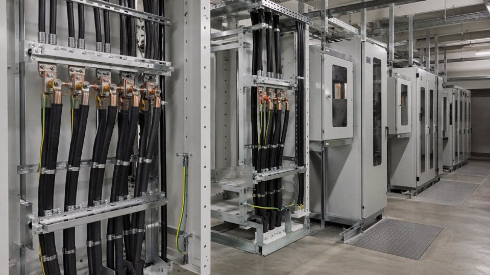
Five production bases across China, totalling 470,000 m² of manufacturing space, with dedicated lines for low-voltage distribution cables, medium-voltage XLPE cables, special-purpose and instrumentation cables, and bare conductor products. That segregation matters more than the floor area number. When a project schedule requires simultaneous delivery of, say, 66 kV XLPE feeders, armoured LV sub-distribution cables, and bare ACSR overhead conductors, a manufacturer without dedicated lines will queue them. Jinda runs those product families in parallel, which is the only realistic way to hit coordinated ship dates on a complex multi-product schedule without pulling work from a subcontractor whose quality you cannot verify.
Quality Infrastructure: From Line-Side Testing to FAT
In-line testing on the extrusion and stranding floors covers conductor resistivity at the draw bench and spark testing on insulation as it exits the crosshead — not as a final audit step, but continuously, so a fault triggers a stop before kilometers of reel are affected. That’s standard practice at serious cable plants; where Jinda goes further is in type-test capability. Partial discharge, impulse withstand, and four-point bending tests are run in-house, which shortens the loop between a design iteration and validated data considerably.
For critical infrastructure buyers — grid operators, EPC contractors working under IEC 60840 or similar regimes — the laboratory is open to third-party witness testing and formal factory acceptance testing (FAT). In practice, most buyers in the Middle East and Southeast Asia request FAT on HV and MV orders; having a calibrated, accessible lab rather than shipping samples to an external test house saves roughly two to four weeks on project timelines, depending on the testing lab’s queue.
Jinda's in-house testing facilities support factory acceptance testing (FAT) by third-party witnesses for critical infrastructure buyers.True
This is consistent with standard practice at large, integrated cable manufacturers supplying IEC-governed grid and infrastructure projects, where buyer-side FAT is a contractual requirement.
R&D That Moves Faster Than a Catalogue
The internal research centre is working on cable constructions for offshore wind array and export cables, HVDC submarine systems, and high-power EV charging infrastructure — three segments where the IEC standards are still evolving and catalogue products frequently need project-specific adaptation. A manufacturer that can modify conductor cross-section, insulation wall thickness, or sheath compound to a project specification — and back it with in-house type-test data — is genuinely different from one that ships what’s in the brochure and calls it close enough.
Supply to 50-Plus Countries: The Paperwork Is Half the Job
Products have reached customers across Europe, the Middle East, Southeast Asia, Africa, and the Americas. Any experienced international procurement manager knows that cable quality is only part of the problem — the other part is packing specifications, country-of-origin documentation, LC versus open-account terms, and local regulatory markings. Jinda’s export team handles all of it routinely, including documentation packages for letters of credit, CAD payment terms, and the certificate bundles that customs authorities in markets like Saudi Arabia, Nigeria, or Vietnam actually require.
Technical Support Before, During, and After Commissioning
Field application engineers are available from tender stage — helping specify cable cross-sections, select armour types, and review installation drawings — through factory acceptance and into post-commissioning fault analysis if something unexpected surfaces. That last part is undervalued. When a sheath fault shows up six months after a cable is buried, having a manufacturer who will engage technically rather than deflect liability is worth considerably more than a slightly lower unit price.
Submit your project cable schedule or specification to Jinda’s international sales team. With 36 years of integrated manufacturing behind each quotation, the response will be technical and commercial — lead times, not just list prices.