Specifying the wrong cable system for a long-span structure doesn’t just mean a failed inspection — it means remediation costs that routinely dwarf the original material budget, schedule overruns measured in months, and in the worst cases, a roof geometry that creeps under sustained load because the wire rope’s actual breaking strength was misread from a translated datasheet. Procurement teams that treat architectural cable as a commodity line item alongside conduit and tray are the ones calling engineers back to site six months after handover.
Cable in architecture refers to high-strength steel wire assemblies — typically with tensile strengths between 1,570 MPa and 1,860 MPa — used as primary structural elements to carry tension loads across long spans. These systems form the load-bearing skeleton of cable-supported roofs, suspension bridges, façade bracing, and tensile membrane structures, enabling clear spans that conventional steel or concrete frames cannot achieve economically.
What makes this genuinely interesting — and genuinely complicated for procurement — is how much structural and material engineering is compressed into what looks, from a distance, like a simple wire rope. The global market for these systems was sitting around USD 1.8 billion in 2023 and is tracking upward at roughly 6% annually, which tells you the demand is real and broadening across building types. But market size doesn’t tell you which strand construction survives a coastal chloride environment for 30 years, or why two cables with identical nominal diameters can have load ratings that differ by 20% depending on lay angle and core type. That gap between catalogue and reality is where most specification errors happen.
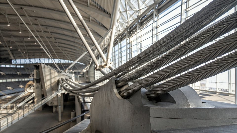
A Structural Taxonomy: Seven Core Types of Cable Used in Buildings and Bridges
Not all architectural cable is interchangeable. Specifying the wrong type — say, using a standard wire rope where a locked-coil rope was needed on a coastal canopy — costs you in corrosion allowance, replacement cycles, and sometimes the whole facade system. What follows is a working classification, organised by construction type, with the material properties and application fit that actually drive procurement decisions.
Wire Rope (Stranded Cable)
The workhorse of structural cable. Wire rope is built from individual cold-drawn wires twisted into strands, then the strands helically wound around a central core. The three standard configurations — 7-wire, 19-wire, and 37-wire — trade off flexibility against metallic cross-section and axial stiffness. A 7-wire strand is stiff and efficient; a 37-wire construction bends more easily but has a lower elastic modulus, typically 150–165 GPa depending on lay angle and construction class.
Diameters run from roughly 6 mm (facade bracing, glass clamp ties) up to 160 mm and beyond for main suspension bridge hangers. For tension rod applications in lightweight steel canopies you’re usually sitting in the 20–50 mm range. The key thing to track on wire rope is the fill factor — what percentage of the nominal cross-section is actually steel — because that drives your working load calculation more than catalog diameter does.
Locked-Coil Rope
The outer layer of a locked-coil rope uses Z-shaped or wedge-shaped wires that interlock, giving you a near-circular, smooth external surface. That surface detail is not cosmetic. It dramatically reduces water ingress, cuts aerodynamic drag compared to open-strand rope, and extends the inspection interval in exposed environments. Long-span roofs over 100 m and cable-stayed bridges both favour locked-coil construction for exactly this reason. Elastic modulus lands around 160–175 GPa — slightly higher than equivalent stranded rope because the interlocking geometry resists wire migration under load.
Parallel Wire Strand (PWS)
Individual wires are arranged in a parallel bundle with essentially zero lay angle. That geometry is why PWS achieves the highest elastic modulus of any rope construction — roughly 200–205 GPa in practice, which gets you measurably less sag and deflection under live load. Main cables on large suspension bridges are almost universally PWS for this reason. The tradeoff is bending radius: PWS cables do not tolerate tight curvature, so they suit long straight runs between anchorages, not routed facade systems.
Structural Strand (Bridge Strand)
Factory-fabricated to defined length with swaged or socketed end fittings already installed, structural strand ships as a component rather than a bulk product. Governing specs are usually ASTM A586 or EN 12385-10. Cable-net facades — those glass walls you see on airport terminals and sports venues — rely heavily on pre-fitted structural strand because site splicing of architectural cable is slow, inconsistent, and frankly where most installation errors originate.
Rod and Bar Systems
Solid or threaded rods in grade S460 through S700 high-strength steel. Minimal diameter, clean visual profile, no rope curvature to accommodate. Glass fin facades, tension ties in atria, catenary hangers in retail interiors — anywhere the architect wants the structural element to disappear. The operational caveat is thread fatigue: under vibrating or cycling loads, poorly torqued rod couplers work loose, which is a maintenance headache that shows up three to five years post-completion if the installation team skipped preload verification.
Fiber-Reinforced Polymer and CFRP Cables
Carbon fiber reinforced polymer cables are the least common type on current projects but the fastest-growing segment for good reason. Corrosion immunity is absolute, which matters enormously in coastal infrastructure, chemical plant canopies, and bridge rehabilitation in salt-spray environments. Tensile strength can reach 2,200–2,400 MPa depending on fiber volume fraction and resin system — comfortably above the 1,570–1,860 MPa range of structural steel wire. The elastic modulus of CFRP cable typically falls around 140–160 GPa, lower than PWS steel, so deflection calculations need revisiting if you’re substituting.
CFRP cables offer complete corrosion immunity compared to steel wire cablesTrue
Carbon fiber itself does not corrode electrochemically. The limiting factor in CFRP cable durability is the resin matrix and end-fitting interface, not the fiber, making CFRP a genuinely superior choice in chemically aggressive environments compared to uncoated steel wire.
Cost per installed meter runs two to four times that of equivalent steel cable right now, though the maintenance savings over a 30–40 year life cycle often close the gap in aggressive environments.
Pre-Stressed Concrete Tendons vs. Architectural Cable
The line here is blurrier than most structural drawings suggest. Post-tensioned tendons in concrete — ASTM A416 low-relaxation strand, typically 12.7 mm or 15.2 mm diameter — carry tension loads through exactly the same mechanical logic as an external architectural cable. The difference is context and visibility. Tendons are embedded, prestress the surrounding concrete, and are rarely sized or specified by architects. External architectural cables are exposed, carry direct tension between discrete nodes, and are part of the structure’s legible geometry.
Where they genuinely overlap is in hybrid systems: cable-stayed roof structures where post-tensioned concrete ring beams anchor external strand, or in concrete box girder bridges with external unbonded tendons running inside the section but fully accessible for inspection. In those cases the specification line between “tendon” and “cable” is a matter of vocabulary, not engineering function.
How Structural Cables Actually Work: Tension, Catenary, and Pre-Stress Explained
A cable is, mechanically speaking, a single-purpose structural member. It carries tension. That’s it. It cannot resist compression, and it has essentially no bending stiffness — try to push on a wire rope and it simply deflects or buckles out of the load path entirely. This sounds like a limitation, and in the wrong system it is. But when a structure is configured correctly, that single-mindedness becomes a major efficiency advantage: every fiber of the cross-section is working at roughly the same stress level, which is something a beam or column can never claim.
The practical consequence is that the entire structural geometry must be arranged so that every load case — dead load, live load, wind, snow drift, asymmetric crowd loading — always keeps the cable in tension. If any load combination can drive a cable to zero tension and beyond, the system is either under-designed for pre-stress or geometrically wrong. This isn’t a theoretical concern. Slack cables under wind-induced flutter have caused real fatigue failures, and the fix is almost never “add more cable” — it’s usually a pre-stress problem that should have been caught in the form-finding stage.
Catenary and Parabola: Two Shapes That Matter
When you hang a cable freely between two supports and let gravity act on it, the shape it takes is a catenary — a curve described by the hyperbolic cosine function, not a parabola, though the two look similar at shallow sags. The distinction matters when you’re computing precise geometry for fabrication. Under a uniformly distributed load (a concrete deck, for example, or a consistently loaded roof membrane), the equilibrium shape shifts to a true parabola. Engineers exploit both. The natural geometry of a loaded cable is inherently efficient because it eliminates bending moments almost entirely from the cable itself — the load is carried purely through the axial tension path.
Sag-to-Span Ratio: Every Choice Has a Cost
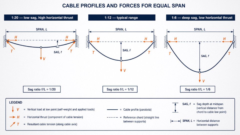
The sag-to-span ratio is one of the more consequential design decisions in a cable roof, and there’s genuine tension (in the non-structural sense) between competing constraints. A shallow ratio — say 1:20 to 1:10 — keeps the roof profile flat, which often suits architectural intent and minimizes headroom loss. But shallow sag means the cable is nearly horizontal, and the horizontal component of the tension force gets very large. The anchor points, pylons, or perimeter compression ring must absorb that thrust, which drives up foundation and ring-beam costs substantially. Deeper sag, somewhere around 1:8 to 1:6, reduces horizontal thrust significantly but eats into usable vertical space and changes the visual character of the structure. In practice, most long-span cable roofs end up in the 1:12 to 1:8 range — a compromise that depends heavily on site geometry, foundation conditions, and what the architect is willing to accept.
Why Pre-Tensioning Is Non-Negotiable
A cable with no initial tension is structurally unreliable under anything but perfectly symmetric, static loading. Real buildings experience wind gusts, uneven snow accumulation, maintenance loads on one side of a roof — all asymmetric. Without pre-stress, these conditions can drive some cables slack while others carry the full load. That load redistribution can be sudden and the resulting geometry change amplifies dynamic response.
Initial tension is typically set at 10–25% of the cable’s rated breaking load, though the exact value depends on the expected live-to-dead-load ratio, the cable’s sag geometry, and whether dynamic loads (seismic, wind flutter) govern the design. Higher pre-stress improves stiffness and stability but increases demands on the anchoring system — there’s no free lunch.
Pre-tensioning architectural cables to 10–25% of breaking load is standard practice to prevent slack under asymmetric or dynamic loading.True
This range is consistent with published guidance from organizations including the Federation Internationale de la Precontrainte and standard practice documented in structural engineering references for cable-supported roofs and bridges.
Load Path and the Compression Partner
Every tension cable needs somewhere to push. The load path in a cable structure always terminates in a compression element — a concrete foundation block, a steel mast or pylon, a perimeter compression ring, or a stiff edge beam. This is fundamental: cables and compression members are structural partners, not competitors. A cable-stayed roof that looks like it’s “floating” is actually transferring enormous forces into masts or perimeter frames that are working extremely hard in compression and bending. Getting that compression element wrong — undersizing the ring beam, for instance — is how cable structures fail at the supports rather than in the cables themselves.
Form-Finding Before Analysis
Before any conventional structural analysis can run, a tensile structure needs its equilibrium geometry established under its governing load pattern. This is called form-finding, and it’s iterative — you don’t start with a shape and check if it works, you let the physics determine the shape. Methods include force density approaches and dynamic relaxation, both of which arrive at the natural equilibrium form through successive approximations.
The software that handles this in serious practice includes SOFiSTiK for integrated analysis and code-checking, Rhinoceros with Karamba3D for early-stage form exploration (especially useful when architects are involved in geometry decisions), and ANSYS for high-fidelity nonlinear analysis when the project justifies it. Skipping or shortcutting form-finding is one of the more reliable ways to end up with a cable geometry that looks fine in a linear static model and behaves badly under real loads.
Material Standards and Specifications: What Engineers Write Into Cable Contracts
Getting the mechanical design right is only half the battle. The other half — the part that causes procurement headaches, delivery delays, and disputes during installation — is translating that design into contractual language that a mill, a fabricator, and a project auditor can all interpret the same way. Vague specifications get you vague product.
The Standards That Actually Govern Procurement
Most international projects reference one or more of the following:
ASTM A586 covers galvanized structural strand, specifying construction, diameter tolerances, and minimum breaking force. It’s common on North American projects and in markets that follow US procurement norms. ASTM A603 handles zinc-coated structural wire rope specifically — different construction from strand, different performance envelope.
The EN 12385 series is the workhorse standard in Europe and, increasingly, the Middle East. Parts 3, 4, 6, and 10 cover wire ropes for general, crane, passenger ropeway, and structural applications respectively — you need to specify the right part number, not just “EN 12385,” or you’ll get argument at inspection. ISO 2408 is harmonized closely with EN 12385-4 for general-purpose wire rope and travels well across jurisdictions.
GB/T 20118 is the Chinese national standard for steel wire ropes and is the governing norm for cables produced within China. It maps reasonably well to ISO 2408 in most structural categories, which matters when you’re sourcing from Chinese mills for Southeast Asian or Middle Eastern projects — the relevant equivalencies need to be stated explicitly in the contract, not assumed.
Minimum Breaking Force and Safety Factors
MBF is the value you see on the mill certificate. WLL — working load limit — is derived from it by applying a safety factor. For permanent architectural structures, that factor is usually somewhere in the 2.5:1 to 3.0:1 range, depending on load combination philosophy and the applicable building code. Life-safety applications — a cable holding a glass canopy over a public entrance, for instance — often require 5:1 or higher.
Mill certificates must state MBF, breaking load test results from actual production coils, and the testing standard used. If the certificate doesn’t reference a named standard for the test procedure, push back. A number without a test method is just a number.
Tensile Strength Grades and What They Mean in Practice
Wire grades run 1,570 / 1,670 / 1,770 / 1,860 MPa. Higher grade means smaller cable diameter for the same MBF — useful when you’re trying to hit an architect’s slender aesthetic target, or when clamp hardware is constraining the cable size. The tradeoff is that higher-strength wire is less ductile, so end-fitting zones need careful design. Spelter sockets on 1,860 MPa wire demand tighter quality control on the zinc or resin fill process than they do on 1,570 MPa strand. Specify the grade explicitly; don’t leave it to the mill to optimize.
Corrosion Protection: Choose Based on Exposure, Not Budget Alone
Four options dominate architectural cable projects:
| Protection Type | Typical Service Life | Best Fit | Maintenance Note |
|---|---|---|---|
| Hot-dip galvanized (≥260 g/m² per EN 10244) | 25–40 years, depending on environment | Inland, moderate humidity | Inspect zinc condition every 5–7 years |
| HDPE sheathing over galvanized core | 30–50 years | Exposed exteriors, UV environments | Check sheath integrity at end fittings annually |
| Epoxy-filled locked coil | 30–45 years | Long-span stay cables, coastal | Essentially zero water ingress if sealed correctly |
| Stainless steel 316L | 50+ years in most environments | Marine, aggressive industrial | Higher upfront cost; watch for crevice corrosion under fittings |
Galvanizing is fine for a covered atrium. A coastal stadium roof is a different conversation — 316L or epoxy-filled locked coil earns its cost premium within the first maintenance cycle.
End Fittings: Termination Is Where Failures Start
Spelter sockets — open or closed, zinc-poured or resin-filled — are the most common termination for structural strand and locked-coil cables. When properly installed, they develop full cable MBF. Swaged ferrule fittings are compact and clean-looking, popular with architects, but their strength efficiency is somewhat lower and depends heavily on the swaging machine calibration and the operator. Fork and eye terminals, and adjustable fork-and-pin connections, add the ability to fine-tune length on site — critical when pre-stress tolerances are tight.
Every fitting type should be proof-load tested to a defined percentage of MBF before leaving the fabrication shop. That requirement belongs in the contract, not as an afterthought at the site inspection.
Fatigue and Relaxation
Stadium roofs and pedestrian bridges cycle under dynamic loads continuously. Specifying static strength alone isn’t enough. EN 1337, and many project-specific protocols, require fatigue testing to defined stress ranges over a specified number of cycles — commonly in the range of 2 million cycles, though the actual requirement depends on the load spectrum analysis. Cable relaxation under sustained load is a separate concern; locked-coil and parallel-wire cables typically relax less than conventional wire rope, which matters when you’re holding pre-stress tolerances over decades.
GB/T 20118 and ISO 2408 cover sufficiently similar wire rope construction and testing requirements that cables manufactured to GB/T 20118 can, with proper documentation, satisfy ISO 2408-referenced project specifications in most structural cable applications.True
Both standards govern steel wire rope construction, dimensional tolerances, and mechanical properties along broadly aligned parameters. Project auditors generally accept GB/T 20118 compliance when accompanied by full mill certificates and third-party test reports, provided the specific mechanical values (MBF, wire grade) are explicitly verified against the project specification rather than assumed equivalent.
Jinda’s production lines operate under GB/T 20118 as the baseline, with parallel compliance documentation prepared for EN 12385 and ASTM A586/A603 where export projects require it. That dual-track documentation process is something worth confirming with any Chinese supplier before contract award — the standard is one thing, the audit trail the overseas project engineer actually needs is another.
Iconic Cable Architecture Projects: Lessons Drawn from Real Structural Applications
The gap between theory and practice in structural cable engineering is wide enough to swallow a project budget. These structures close that gap.
The Millennium Dome, London (Now The O2)
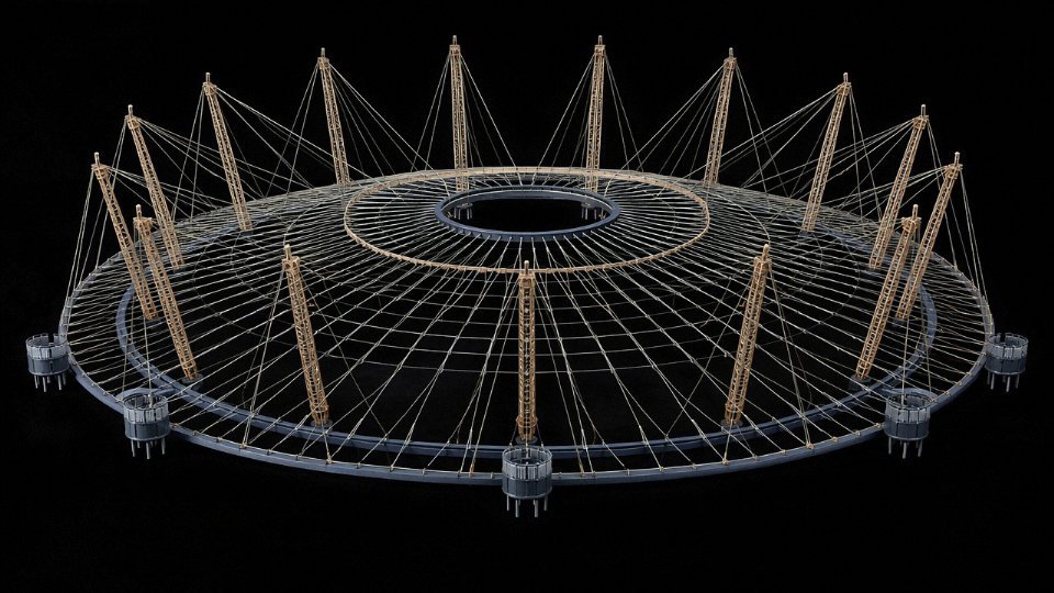
At 365 meters diameter, the Millennium Dome remains one of the largest tensile roof structures ever built. Twelve steel masts — each roughly 100 meters tall — support a radial and circumferential cable net from which a PTFE-coated fiberglass membrane is suspended. The primary cables are parallel wire strands and locked-coil ropes in the 80–100 mm diameter range, with working loads that demanded wire strengths at or above 1,770 MPa.
What this project illustrates for procurement engineers is the long-game problem. The dome opened in 1999 and has now been in service for over 25 years under a heavily modified load program — concerts, large crowds, changed internal equipment loads. Pre-stress monitoring wasn’t optional; it was designed in from the start, with load cells at anchor points and a documented inspection schedule. If you’re specifying cable for any tensile membrane structure with a 25-plus-year intended life, assume the monitoring hardware and its integration with anchorages needs to be in the cable package from day one, not bolted on later.
Beijing National Stadium (Bird’s Nest, 2008)
The Bird’s Nest roof isn’t a pure cable structure — it’s a steel truss system with cable tension ties integrated into the saddle roof geometry. That distinction matters. The cables here function as precision-loaded tie rods within a primary steel frame, and they had to perform in a seismic zone while meeting both Chinese GB/T standards and international scrutiny given the project’s profile.
The Beijing National Stadium was engineered to meet Chinese GB/T structural steel and cable standards while satisfying international peer-review quality requirements for the 2008 Olympics.True
The project was subject to both Chinese national standards and independent international structural review, consistent with Olympic infrastructure procurement protocols documented in engineering literature of that period.
The engineering lesson: seismic zones change the fatigue loading picture significantly. Cables in seismic applications need specified low-cycle fatigue performance, not just static ultimate load capacity. This is the kind of detail that disappears in a generic RFQ and surfaces at the worst possible time.
The Alamillo Bridge, Seville (Calatrava, 1992)
Thirteen pairs of stay cables connect a 142-meter inclined pylon to the bridge deck — and there are no back-stays. Calatrava balanced the pylon’s lean against the cable tension alone, which means every cable is doing real structural work with no redundancy from a back-span anchor. The pylon is deliberately heavy to compensate. It’s an elegant solution that leaves almost zero tolerance for relaxation or creep in the stays over time. Galvanized locked-coil or stranded stays with HDPE sheathing were used, which by 1992 was already the industry standard for exposed marine-adjacent environments like Seville’s riverside.
The procurement takeaway: single-pylon cable-stayed configurations demand tighter manufacturing tolerances on cable length and stiffness than multi-pylon bridges, because adjustment capacity at the anchor heads is limited once you’ve committed to the geometry.
Apple Park Visitor Center, Cupertino
Forty-four custom cables support a carbon-fiber roof structure over an all-glass enclosure. These aren’t off-the-shelf catalog ropes — they’re precision-machined assemblies where the terminal fittings are as engineered as the wire core, tolerances run to fractions of a millimeter, and every cable was proof-loaded and certified before installation. This is architectural cable at its most demanding intersection with facade engineering.
For procurement managers, Apple Park is a useful calibration point: when the cable is also a visible architectural element within meters of the public, surface finish specifications, coating consistency, and dimensional tolerances become contractual items, not afterthoughts. Factory acceptance testing (FAT) at the manufacturer’s facility — not just certificate review — is the only reliable gate.
A Large Stadium Canopy in the Gulf Region
Consider a realistic project scenario: a 60,000-seat stadium canopy in a Gulf state requiring roughly 850 tonnes of 75 mm locked-coil rope. Hot, humid, salt-laden air makes corrosion protection the dominant specification driver — not tensile strength, which is rarely the limiting constraint at this scale. The typical solution is hot-dip galvanized wire plus a filled locked-coil construction to minimize void space, combined with HDPE outer sheathing rated for UV exposure at 40°C-plus ambient. Shipping from Chinese manufacturing bases to Gulf ports runs 25–35 days by sea, but that’s the easy part. Fabricated cable systems with swaged or socketed end fittings typically require 16–24 weeks from confirmed order to shipment-ready, depending on complexity and whether custom terminal geometry is involved.
Getting that timeline wrong by even six weeks can cascade into a structural steel erection delay — because you can’t tension the structure until the cables arrive, and you can’t close the roof until it’s tensioned. Early supplier engagement at design-assist stage, not just at tender, is what prevents that scenario. Jinda’s multi-base manufacturing capacity in China gives procurement teams the option to confirm lead times and production slots before the design is fully frozen, which is how the Gulf’s most schedule-sensitive projects manage this risk.
Synthesized Lessons
Across these projects, a few patterns hold regardless of geography or building type. Early cable supplier involvement — ideally at design development, not construction documents — prevents the expensive rework that happens when fabrication drawings don’t match procurement reality. Factory acceptance testing before shipment is non-negotiable for any cable that carries a primary structural load; shipping a problem back from site costs ten times what catching it at the factory does. And long-lead procurement planning for fabricated cable systems should be built into the project schedule as a constraint, not discovered mid-program. Sixteen to twenty-four weeks is a real number. Plan around it.
Architectural Cable in Facade and Glass Systems: Technical Requirements for Curtain Walls
Cable net facades are a genuinely distinct engineering sub-discipline — not just a scaled-down version of roof cable work. The system is conceptually straightforward: a grid of horizontal and vertical stainless steel cables, pre-tensioned against a perimeter boundary frame, creates a stiff planar membrane to which large glass panels are point-fixed using spider fittings. The result is a fully transparent, column-free building envelope that transmits wind load through pure tension rather than bending. In practice, getting that to work reliably across decades of thermal cycling, wind gusting, and building movement is considerably more involved.
Cable Sizes and Tolerance Requirements
Facade cables run 12 mm to 40 mm in diameter for wire rope systems; rod systems typically fall in the 20 mm to 60 mm range. Both are dramatically smaller than the 60–130 mm cables you see in long-span roofs, but the fabrication standards are tighter, not looser. A ±1 mm length error across a 15-meter vertical cable can mean a glass panel is visibly out of plane — something a structural roof cable would simply absorb. Dimensional inspection reports are not optional here; every assembled cable in the package needs one. Surface finish matters too, because these cables are on permanent public display, often within arm’s reach. Weld marks, machining chatter, or inconsistent strand lay are commercially unacceptable regardless of structural adequacy.
Wind Load Design and Pre-Tension Calibration
The critical design case for facade cables is usually suction, not positive pressure. Wind pulling glass outward reduces cable tension, and if the pre-tension is set too low, individual cables go slack under peak suction loads, allowing glass panels to rack or rotate at their spider fittings. Facade engineers typically calibrate pre-tension so that the net tension in any cable remains above roughly 10–15% of its working load under the worst suction case — the exact margin depends on the aspect ratio of the cable grid and the code-specified wind speed for that site.
Material Selection: 316L vs. Galvanized Carbon Steel
Grade 316L stainless steel dominates visible facade applications. Its non-magnetic and corrosion-resistant properties are genuinely necessary in urban coastal environments, and the austenitic microstructure avoids stray-current concerns in buildings with sensitive electronic infrastructure nearby. For enclosed atria, interior cable walls, or lower-budget facade schemes, hot-dip galvanized carbon steel is a legitimate alternative — it carries higher tensile strength for a given diameter and costs considerably less, but maintenance obligations change substantially, and the zinc surface needs periodic inspection in humid or chemically aggressive environments.
Grade 316L stainless steel is non-magnetic and offers superior corrosion resistance compared to standard 304 stainless steel in chloride-rich environments.True
316L contains 2–3% molybdenum, which significantly improves pitting resistance in chloride exposure. Its low carbon content also reduces sensitization risk during welding. This is well established in materials standards including ASTM A276 and EN 10088.
Vibration and Resonance
Slender, highly tensioned facade cables have low mass and can experience aeolian vibration — wind-induced resonance — at frequencies typically in the 10–100 Hz range depending on cable length and tension level. In most projects this is a secondary concern handled by cross-ties between the horizontal and vertical cable grid, which effectively shorten the free vibrating length. On particularly slender single-cable elements, tuned mass dampers or elastomeric damping inserts at the end fittings are sometimes specified. Ignoring it is usually fine on short cables; on tall single-story atrium walls with 10+ meter vertical runs, it warrants explicit checking.
Connection Geometry and Supply Coordination
Spider fittings — the stainless castings that grip the glass at each corner — are fabricated to tight angular and positional tolerances. The cable end-fitting geometry, usually a swaged or threaded terminal, must coordinate millimeter-by-millimeter with the facade engineer’s connection detail. This is where procurement errors tend to surface: a cable supplier working from a generic schedule without reviewing the facade engineer’s shop drawings will almost certainly deliver fittings with wrong thread lengths or rotational stop positions. Facade cable assemblies should always be supplied fabricated-to-length with load-test certificates, and ideally a pre-assembly check against a physical connection mock-up before full-batch production is released.
Specifying, Procuring, and Installing Architectural Cable: A Project Manager’s Workflow
Getting cable architecture right on paper is one thing. Executing it through procurement, fabrication, delivery, and installation without burning schedule or budget is another discipline entirely. The workflow below reflects how projects actually run — not how they look in a textbook.
Stage 1 — Design Assist and Early Supplier Engagement
Bring a cable supplier into the conversation during schematic design, typically months 1–6. This is not a sales call. You need real data: what diameters are held in stock versus made-to-order, which end-fitting configurations are standard off the shelf, and what lead times look like for your tonnage. Structural engineers who finalize geometry before talking to any manufacturer often design themselves into a corner — specifying a 68 mm locked-coil rope that carries a 14-week fabrication premium when a 72 mm strand would have shipped in four.
Lead times for architectural cable assemblies with machined sockets typically run 10–20 weeks depending on order volume, steel mill schedules, and whether the end fittings require hot-dip galvanizing or electropolishing. Seasonal steel demand spikes, particularly in Q1 when Chinese mills restart after the Lunar New Year period, can stretch that by 3–5 weeks.
Stage 2 — Writing a Performance-Based Specification
A good cable spec defines what the cable must do, not which catalogue number to buy. State the minimum breaking force (MBF) required, the design fatigue life (usually expressed in load cycles at a defined stress range), the corrosion protection class per ISO 4309 or project-specific equivalent, dimensional tolerances on diameter and length, and the full factory acceptance test (FAT) protocol. Avoid referencing a single manufacturer’s proprietary socket geometry unless you have a sole-source justification in writing — that kind of spec locks out competition and, in public procurement, creates legal exposure.
Stage 3 — Tender and Supplier Qualification
ISO 9001 certification alone is sufficient to qualify a cable manufacturer for a structural architectural project.False
ISO 9001 covers quality management systems but says nothing about a manufacturer's specific capability to produce high-tensile structural cable to architectural tolerances. Mill audit reports, third-party test certificates traceable to accredited labs, and documented reference projects in comparable applications are all necessary additional evidence.
Red flags worth walking away from: test certificates that reference a lab you cannot find independently, pricing that sits 30–40% below every other tender (FAT alone costs money; someone is skipping it), and reference lists that name projects but cannot supply contact names or engineer-of-record documentation.
Stage 4 — Factory Acceptance Testing
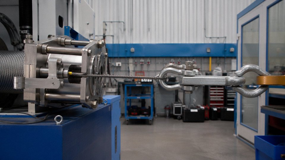
FAT on structural architectural cable typically includes a proof load test to roughly 50% MBF, dimensional verification, coating thickness measurement per the specified standard, and end-fitting pull-out tests on a sample percentage of assemblies. Witnessing this in person — or through a qualified third-party inspector like Bureau Veritas or SGS — is not a luxury on any project where a cable failure means structural collapse or glass-panel ejection over occupied space. Remote video calls are not a substitute.
Stage 5 — Logistics and Site Storage
Long cables — some facade stays exceed 40 m, main roof cables can run well past 100 m — need to be coiled onto purpose-built drums with anti-kink radii specified in the purchase order, not worked out on the loading dock. Cables crushed or kinked during shipping develop localized stress concentrations that no amount of pre-tensioning corrects. Specify minimum drum diameter as a multiple of cable diameter (commonly 30× or greater), require timber crating for socketed ends, and plan laydown area on site before the delivery date, not after.
Stage 6 — Installation and Tensioning Sequence
The tensioning protocol is a structural engineering deliverable. Full stop. Each cable tensioned shifts load into every adjacent cable; install them in the wrong order and you can overstress elements that were fine on paper, or worse, introduce out-of-plane deformation that the facade system cannot accommodate. A qualified rigger is essential, but they execute the engineer’s sequence — they do not write it.
Stage 7 — Post-Installation Monitoring and Maintenance
Galvanized structural strand typically delivers 30–50 years of service life with proper maintenance; stainless rope in benign indoor environments can extend beyond that, though its higher initial cost needs to be justified by the client’s maintenance budget reality. Visual inspection intervals of 12–24 months are common, supplemented by acoustic emission monitoring for wire breaks in high-consequence applications. Rope interiors — particularly spiral strand — need periodic re-lubrication because the factory-applied grease migrates over time, especially in warm or humid climates. Skipping re-lubrication for a decade is one of the faster ways to turn a 40-year cable into a 20-year cable.
Sustainability and Lifecycle Performance: Why Cable Structures Score High on Green Metrics
Sustainability has moved from a checkbox on grant applications to a hard procurement requirement. Clients carrying ESG commitments, project teams chasing LEED Platinum or BREEAM Outstanding, and public-sector owners under embodied-carbon scrutiny all ask the same question earlier in the design process: what is the structural system’s environmental footprint? Cable architecture holds up well under that scrutiny — but the argument is more nuanced than “less steel equals greener.”
Material Efficiency: Doing More With Less
The core case starts with mass. A cable-supported roof spanning 250–300 meters will typically use somewhere in the range of 30–50% less steel by mass compared with a conventional truss or portal frame covering the same area, though the actual figure depends heavily on geometry, load case, and how aggressively the engineer has optimized the truss alternative. The reason is straightforward: a cable working in pure tension mobilizes nearly the full cross-sectional strength of the wire, while a compression member in a truss must be sized against buckling, which drives up section size well beyond what pure stress calculations would require. You’re carrying the same load with a fraction of the material.
That efficiency compounds. Lighter roofs mean lighter secondary structure, lighter columns, and — often overlooked — lighter foundations. In poor ground conditions, foundation cost can represent 15–25% of total structure cost. Reducing superstructure dead load is one of the few levers that genuinely propagates savings downward through the entire load path.
Embodied Carbon: The Numbers and Their Limits
Steel wire rope carries an embodied carbon intensity of roughly 2.5–3.0 kg CO₂e per kg, which is broadly comparable to hot-rolled structural steel sections. So per kilogram, cable doesn’t look dramatically better. The advantage appears when you calculate per square meter of covered area: because you need far less of it, the total embodied carbon per functional unit — a square meter of sheltered floor or roof — drops substantially. For long-span structures in particular, this is where the green argument becomes genuinely compelling rather than rhetorical.
Cable-supported roof structures can achieve 30–50% lower embodied carbon per square meter of covered area compared to conventional steel truss systems for equivalent long spans.True
This range is consistent with lifecycle assessment data for long-span structures, driven by the mass efficiency of tension-only members and consequent reductions in secondary structure and foundation requirements. The actual figure varies with span, geometry, and foundation conditions.
Longevity Changes the Lifecycle Calculation
Properly protected architectural cables — hot-dip galvanized or duplex-coated stainless — have documented service lives in the 50–80 year range with minimal active maintenance. Compare that with painted structural steel, which in most climates needs repainting every 10–15 years depending on exposure category. Each repaint cycle involves scaffolding, surface preparation, solvent-based coatings, and disposal of waste material. Over a 60-year building life, a conventional steel structure might go through four or five full repaint cycles. The cable system, if correctly specified at the outset, may need little more than periodic inspection and re-tensioning checks.
End-of-Life Recyclability
High-carbon steel wire is fully recyclable through electric arc furnace steelmaking with no significant quality downgrade. In regions with mature scrap markets, recycled content in new wire rod production is already in the 20–40% range, and that proportion is rising as EAF capacity expands globally. This matters for LEED Materials and Resources credits, specifically the Building Product Disclosure and Optimization pathway, where recycled content documentation from the wire rod supplier supports credit achievement. It also matters for clients who will eventually need to demonstrate end-of-life material recovery in ESG reporting.
LEED and BREEAM Credit Pathways
Cable systems don’t earn green credits automatically, but they open doors that conventional heavy structure closes. Transparent cable facades and cable-net glazing maximize daylight penetration, which contributes to LEED EQ credits for daylight and views — and in practice, daylit spaces reduce artificial lighting loads in ways that show up in operational energy bills, not just certification scorecards. Reduced dead load cutting concrete foundation volume addresses embodied carbon in the substructure, relevant under BREEAM’s Materials category. Responsible sourcing documentation — mill certificates, chain-of-custody records for wire rod, ISO 14001-certified manufacturing — feeds directly into the responsible sourcing credits that specifiers frequently overlook until the certification audit.
What to Ask of Your Cable Supplier
Environmental Product Declarations are increasingly requested by certifying bodies and forward-looking clients. An EPD requires the manufacturer to have conducted a lifecycle assessment to ISO 14044 and to hold current ISO 14001 environmental management certification. Jinda maintains ISO 14001 certification across its production operations and has been working to reduce energy consumption in galvanizing lines — zinc bath heating is one of the more energy-intensive steps in cable manufacturing, and incremental efficiency gains there do show up in product-level carbon accounting. Supply chain traceability for wire rod sourcing is the other piece: for projects requiring EPD documentation, knowing the origin and carbon intensity of the rod stock matters. That’s a question worth asking any supplier early, not after the specification is locked.
Frequently Asked Questions About Cable in Architecture
What is the difference between a cable-stayed structure and a suspension structure?
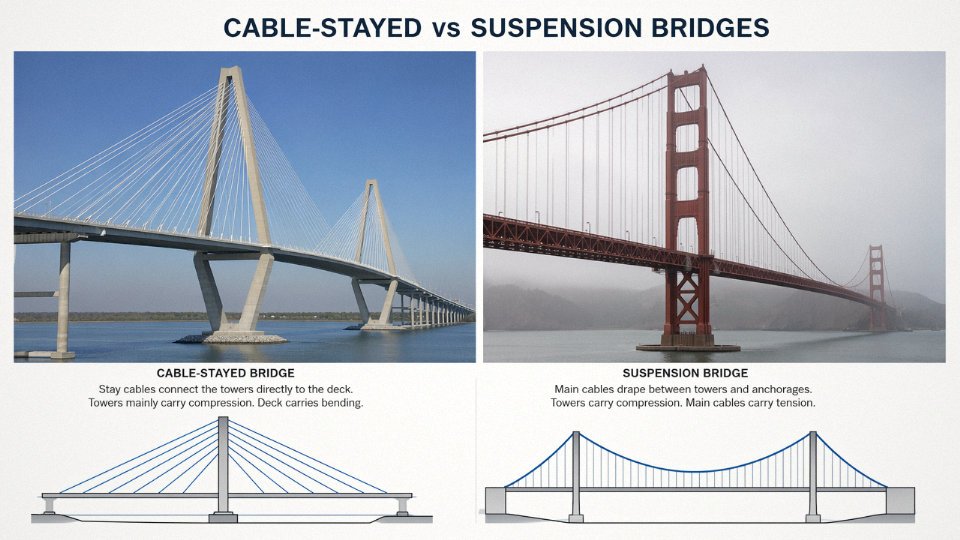
The geometry tells the story. In a suspension bridge or roof, the primary cable hangs in a natural catenary between two anchor points or towers, and vertical hangers drop from that cable down to the deck or roof membrane. The main cable does almost all the work, and the towers are under compression. In a cable-stayed system, individual cables run directly from the tower head to specific points along the deck — fan pattern, harp pattern, or somewhere between — so the deck itself carries significant compression and is considerably stiffer. Cable-stayed systems are generally preferred for spans of roughly 100–500 m because you avoid the enormous anchorage forces a suspension cable demands at each end. For very long spans (think major river crossings above 600–700 m), suspension geometry tends to win on material efficiency.
Can architectural cables be used in seismic zones?
Yes, and in some respects cable systems behave well under seismic loading. Low mass means lower inertial forces, and the geometric flexibility of a tensioned cable system can absorb inter-story drift that would crack a rigid concrete frame. That said, the anchor plates, connection hardware, and any compression struts in the same structural system must be fully designed for combined seismic load cases — the cable itself is rarely the weak point, the anchorage is. Any project in a high-seismicity zone should involve a structural engineer experienced with tension systems specifically; generic seismic detailing for steel frames does not translate directly.
How long does it take to manufacture a custom architectural cable system?
Plan for 12–20 weeks for fabricated assemblies with precision end fittings, from confirmed purchase order to ready-for-shipment. That range depends heavily on end-fitting complexity, whether swaged or socketed terminations require special tooling, and the supplier’s current shop loading. Major infrastructure cables — parallel wire strands for a cable-stayed bridge, for instance — realistically run 24–36 weeks. The engineers who get burned are the ones who treat cable as a late-stage procurement item. It is not rebar; you cannot phone it in at week ten of a twelve-week schedule.
What causes cable fatigue and how is it prevented?
Cyclic loading — wind buffeting, traffic, live loads cycling daily — drives micro-crack propagation in individual wires, usually initiating at surface defects or at termination zones where bending radius is tight. The spec document is your first line of defense: define the fatigue design life explicitly (typically 2 × 10⁶ cycles minimum for dynamic applications) and require the manufacturer to demonstrate compliance. In service, install vibration dampers at L/4 or as the dynamic analysis dictates, maintain minimum bend radius at all deviation points, and schedule periodic acoustic emission testing — this can detect wire breaks before a cable reaches a critical condition.
Are stainless steel cables always better than galvanized cables for external use?
Not always. Grade 316L stainless is the right call for marine environments, swimming pool enclosures, or anywhere chlorides are elevated. But it runs 4–6× the price of hot-dip galvanized carbon steel cable, depending on diameter and market conditions. For inland locations with a 30–50-year design life, galvanized cable with a well-fitted HDPE sheath is often the rational choice — plenty of 40-year-old galvanized roof cables are still in service with only cosmetic surface oxidation. Specify the environment first, then let the corrosion assessment drive the material choice rather than defaulting to stainless because it sounds better.
How do I verify that a cable manufacturer’s test certificates are genuine?
Request mill test certificates tied to specific heat numbers. If the certificate has no heat traceability, it is not useful. Engage an accredited third-party body — SGS, Bureau Veritas, TÜV are the names you will commonly see — to witness factory acceptance testing or at minimum to conduct a document audit. If budget allows, send your own inspector for FAT. Certificates without heat traceability, or factories unwilling to permit third-party witness testing, are warning signs worth taking seriously regardless of how competitive the pricing is.
Jinda's cable assemblies are supplied with mill test certificates traceable to specific heat numbers and can accommodate third-party witness testing by SGS, Bureau Veritas, TÜV, or client-appointed inspectors.True
This is standard practice for manufacturers supplying international infrastructure and architectural projects under EN, ASTM, or equivalent standards, and is consistent with Jinda's stated quality system and international project scope.
What is a typical cable replacement procedure for an aging structure?
Replacement is always done under controlled load transfer. A temporary load path — usually a parallel steel member or a set of come-alongs and spreader beams — carries the structural load while the target cable is de-stressed incrementally and removed. The new cable is then installed and tensioned in the sequence defined by the original structural engineer, because stressing order affects force distribution across the whole system. Work from the original design calculations; if those records are lost, a pre-replacement load survey is mandatory. One cable at a time is the standard practice; replacing multiple cables simultaneously without detailed engineering justification is asking for trouble.
Can Jinda supply both cable and end fittings as a complete system?
Yes. Jinda manufactures complete assemblies covering the wire rope or strand body, precision-machined end fittings (swaged, open or closed spelter sockets, or threaded stud ends), proof-load certification, and dimensional inspection documentation. Receiving a tested, ready-to-install assembly rather than loose components reduces the risk of field assembly errors and simplifies quality sign-off on site — one quality dossier per cable rather than separate records for rope and fittings.
What documentation should I request from a cable supplier for an international project?
At minimum: mill test certificates with heat traceability, dimensional inspection reports, FAT test reports signed by inspector, ISO 9001 certificate, CE marking declaration or equivalent product compliance document per the applicable national standard, packing lists identifying each bundle or reel, and country-of-origin documentation for customs. For LEED or BREEAM projects, request either an Environmental Product Declaration or a written recycled content and embodied carbon declaration. Getting this list into the purchase order before contract award is far easier than chasing it down six months later during handover.
What minimum order quantities apply when procuring from a manufacturer like Jinda?
For standard wire rope in the 16–100 mm diameter range, expect minimums around 5–10 tonnes per diameter and grade — though this shifts depending on how tight the production schedule is and whether the material is a stock item. Custom-fabricated assemblies with unique end fittings are priced and scheduled by the number of distinct cable configurations, not purely by weight. Jinda’s five production bases across China and roughly 470,000 m² of manufacturing footprint mean they can accommodate both large-volume commodity runs and smaller-quantity, high-specification project packages without forcing one customer’s schedule into another’s.