Specify the wrong cable in a control panel and the consequences rarely stay small. A mismatched voltage rating causes insulation breakdown under transient spikes; undersized cores overheat under continuous current draw; the wrong temperature rating embrittles the jacket within a season near a furnace. Any of those faults can trip a production line at the worst possible moment — and the cost isn’t just the cable replacement. It’s the unplanned downtime, the maintenance labor, the scrap batch, and occasionally a safety incident that ends up on an incident report.
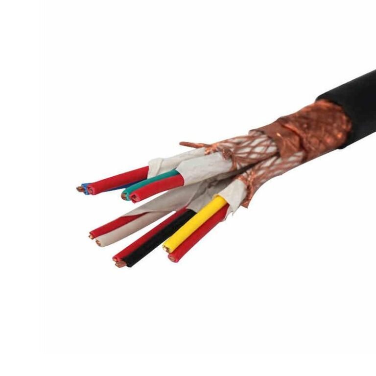
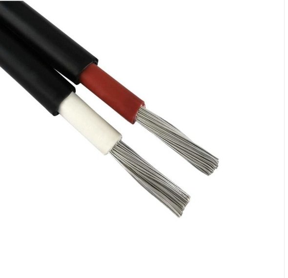
Control cable is used to transmit low-voltage electrical signals and commands between control equipment — PLCs, switchgear, sensors, actuators, and instrumentation panels. Rated typically from 300/500 V up to 1 kV, with conductor sizes from 0.5 mm² to 10 mm², it carries the logic that tells machines what to do, rather than delivering the power that drives them.
What makes this cable category deceptively complex is how many variables converge in a single purchase decision: core count, insulation material, shielding configuration, temperature range, flexibility class, and applicable standards — all of which shift depending on whether you’re wiring a PLC cabinet in a temperate factory or running a multi-core trunk line through an arctic outdoor installation. The sections below work through each of those variables the way a procurement engineer actually has to think about them.
Seven Core Industrial Applications Where Control Cable Is Indispensable
Control cable shows up everywhere once you start looking — but the why differs sharply from one application to the next. Voltage class, core count, sheath chemistry, mechanical flexibility: each environment imposes its own set of demands, and specifying a cable that satisfies one application can get you into real trouble in another.
Motor Control Centers and Variable Frequency Drives
An MCC bay is a punishing environment. You have contactor coils cycling hundreds of times a day, cooling fans running continuously, and the floor underneath invariably sees hydraulic fluid or cutting oil at some point. The multi-core control cable here — typically 7-core or 12-core, 1.5 mm² — ties the start/stop pushbutton station, the overload relay auxiliary contacts, and the VFD’s analog speed reference (usually 0–10 V or 4–20 mA) back to the panel. Because VFDs generate high-frequency switching noise, the cable run for analog speed signals usually needs overall shielding; unshielded cores in that environment will give you erratic speed control that looks like a drive fault but isn’t. PVC sheaths go soft and crack from oil exposure within a year or two; polyurethane or PVC/nitrile compounds hold up significantly better. Flexible construction matters here too — there’s rarely a clean, straight run in an MCC room.
PLC and DCS Automation Panels
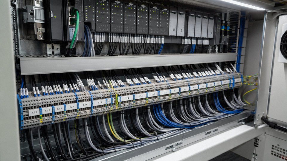
The wiring topology most plants settle on is the home-run approach: a single 19-core or 37-core control cable pulled from the field junction box straight back to the I/O cabinet, rather than running 19 individual wires through separate conduits. Labor savings during installation are real — one well-organized cable pull versus a conduit stuffed with singles that someone has to sort, label, and terminate one by one. For proximity switches, solenoid valve coils, and limit switches scattered around a production cell, 0.75 mm² or 1.0 mm² cores are usually adequate, though anything driving a solenoid with higher inrush should be checked against the actual load rather than assumed.
Crane and Hoist Systems
Festoon and trailing cable configurations on cranes are genuinely harsh duty. The cable flexes and twists with every traverse cycle — a busy overhead crane in a steel fabrication shop might complete 200–300 cycles per shift. Standard stranding fails early under that kind of mechanical fatigue; you need Class 5 or Class 6 fine-stranded conductors per IEC 60228, with an abrasion-resistant PUR sheath that can take contact with the festoon trolley track. Torsion resistance is the spec that often gets overlooked at procurement stage. Buy standard flexible cable here and you’re looking at conductor fractures within months rather than years.
Class 5 and Class 6 stranding per IEC 60228 provide significantly greater flex-cycle endurance than Class 2 solid or stranded conductorsTrue
IEC 60228 defines conductor flexibility classes; Class 5 and 6 use finer individual wire strands, which distribute bending stress across more wires and dramatically extend fatigue life in repeated-flexing applications like crane trailing cables and robotic tow chains.
Building Automation and HVAC Control
BAS wiring for damper actuators, VAV controllers, and chiller start/stop interlocks isn’t particularly demanding electrically — most signals are low-voltage, low-current. What drives specification here is the building code environment. Under EN 50575 and the CPR (Construction Products Regulation), cables installed in occupied commercial or public buildings must carry an appropriate reaction-to-fire classification, typically Cca or Dca depending on the installation route. LSZH sheathing is essentially standard now for any BAS cable in corridors, ceiling voids, or risers. Fire-rated interlock loops — the kind that hold open a smoke damper or trip a smoke extract fan — sometimes require circuit integrity performance under IEC 60331 as well. Skipping that on a specification can create a significant liability issue, not just a performance one.
Renewable Energy — Solar and Wind
Wind turbine nacelles are a demanding environment that catches some procurement teams off guard. The pitch control and yaw control circuits inside the nacelle run in tight conduit near the gearbox, see continuous vibration, and can swing between roughly -25°C and +70°C over a turbine’s operating life. UV-stabilized sheaths matter for any external runs down the tower or across a solar farm’s tracker rows. In utility-scale solar, control cables appear in string monitoring circuits, tracker motor control, and combiner box interlock wiring — applications where the cable may be partly buried, partly exposed to direct sun, and expected to sit there largely unmaintained for 25 years. Specifying adequate UV resistance and a wide operating temperature range (often -40°C to +90°C or beyond) at procurement stage is far cheaper than a mid-life cable replacement across several hundred acres of tracker arrays.
Mining and Heavy Industry
Underground coal mines and quarries add two requirements that most other applications don’t face simultaneously: mechanical armoring and hazardous-area compliance. Steel wire armored (SWA) or aluminum wire armored (AWA) construction per IEC 60502 provides the physical protection against rock fall and vehicle traffic; IECEx or ATEX certification addresses the explosive atmosphere risk. In steel mills and similar heavy industry above ground, armored control cable also protects against rodent damage, forklift impacts, and occasional contact with hot metal scale — all of which are genuinely routine occurrences on that kind of plant floor. The moisture ingress issue in underground installations is serious; cable glands and terminations that allow water tracking along the conductor will cause insulation failures that are both dangerous and difficult to fault-find.
Rail and Transportation Infrastructure
Railway interlocking systems, metro platform screen door (PSD) controllers, and road tunnel ventilation panels share a common specification hierarchy: fire performance comes first, everything else second. IEC 60332-3 covers flame propagation resistance for cable bundles (important because signaling cables often run in dense trays), and EN 45545 sets the fire, smoke, and toxicity requirements for railway rolling stock and fixed installations. A cable that passes IEC 60332-1 in isolation but fails IEC 60332-3 as an installed bundle is not compliant for most rail infrastructure work — a distinction that occasionally causes problems when a supplier substitutes a seemingly equivalent product. Signaling cable in these environments also tends to need good EMI shielding, since it runs alongside traction power infrastructure that generates significant interference.
Anatomy of a Control Cable: How Each Layer Is Engineered for Command-Circuit Duty
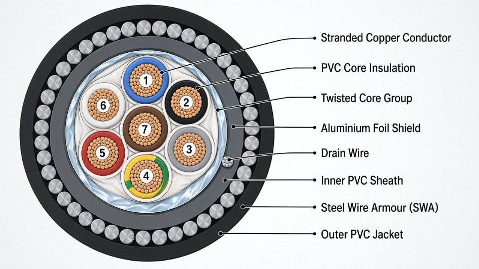
Pull apart any well-built control cable cross-section and you are looking at four to six distinct engineering decisions, each layer compensating for a specific failure mode. Understanding what those decisions are — and why manufacturers make them — is what separates someone who can evaluate a datasheet critically from someone who just compares prices per meter.
Conductor Class: Matching Flexibility to Movement
IEC 60228 defines conductor classes that matter far more than people give them credit for. Class 1 (solid) conductors are entirely appropriate for fixed panel wiring where the cable never flexes after installation — they terminate cleanly in screw-type ferrules and stay put. Class 2 (stranded) is the workhorse for most static cabinet and tray runs: enough flexibility to route through conduit without kinking, but not engineered for repeated movement. Once you move to machine tool cabinets with door-mounted operator panels — a scenario where the cable flexes every time a technician opens the cabinet, potentially thousands of cycles per year — you want Class 5 fine-stranded conductors. Class 6 (extra-flexible, sometimes called “superflex”) is the right answer for festoon crane systems, drag chains, and robotic cable carriers where the conductor itself experiences tight bend radii continuously. Using Class 2 in a drag chain is a false economy; you will see wire fatigue failures inside the insulation that are invisible until a circuit drops intermittently, which is among the more maddening faults to diagnose on a plant floor.
Core Insulation: Temperature, Chemistry, and Cost
PVC insulation, typically designated TI1 or TI2 per older IEC conventions, handles up to 70°C and covers the vast majority of panel and light-industrial wiring economically. XLPE (cross-linked polyethylene) raises the continuous rating to around 90°C and resists oils and certain solvents better than PVC — worth the modest cost premium in chemical plant environments. EPR rubber is also rated to 90°C but stays genuinely flexible down to roughly -40°C or lower, which makes it the practical choice for outdoor arctic installations or unheated warehouses in northern climates. Silicone rubber is in a different category entirely: rated to 180°C, used near furnaces, engine compartments, or anywhere that ambient temperature would degrade anything else. It costs substantially more and is mechanically softer, so it needs protection from abrasion.
Core Identification, Twisting, and Lay-Up
IEC 60446 governs color coding. The familiar green-yellow earth, blue neutral, and brown/black phase sequence applies, though multi-core cables beyond a handful of cores typically rely on numbered cores rather than distinct colors — you simply cannot color-code 19 or 37 cores meaningfully. Core twisting within pairs or groups reduces inductive crosstalk between adjacent circuits; the tighter the twist pitch, the better the rejection, which matters when control circuits share a jacket with others carrying switched DC loads or PWM signals. Concentric layer arrangement — inner cores, then an intermediate layer, then the outer ring — produces a stable round cross-section that feeds predictably through cable glands and strain relief fittings without gaps or ovality. That sounds like a detail, but a flattened or irregular jacket causes IP rating failures at the gland.
Shielding: Choosing the Right EMI Defense
Unshielded cable is acceptable for short, low-noise runs — a few meters inside a grounded steel cabinet, for instance. For anything carrying analog signals or running near variable-frequency drives, shielding is not optional. An overall aluminum-polyester (Al/PET) foil with drain wire gives good coverage above roughly 100 kHz, stays compact, and is inexpensive; it is the most common choice for general instrumentation. Tinned copper braid provides lower high-frequency attenuation but handles mechanical stress better — flexing, vibration — and optical coverage of 85–95% is typical, which matters for installations that move. For multi-circuit cables where different circuits must not interfere with each other inside the same jacket, individually shielded pairs within a collective outer shield is the correct architecture, common in process instrumentation running 4–20 mA loops alongside digital signals.
An overall Al/PET foil shield with drain wire provides effective EMI attenuation primarily above 100 kHz, not at lower industrial power frequencies.True
Foil shields are capacitively coupled and their attenuation is frequency-dependent; at 50/60 Hz power-frequency noise, a foil shield offers minimal rejection unless grounded at both ends with controlled impedance, which is rarely done in control wiring practice.
Armoring: Mechanical Protection That Needs to Match the Installation
Steel wire armoring (SWA) is the standard for direct buried runs and cable tray where tensile loads and crush resistance both matter. Aluminum wire armoring (AWA) saves weight — relevant for suspended trays or offshore platforms — and avoids creating a magnetic circuit around the cable, which SWA technically does in single-core applications. Steel tape armoring (STA) is a middle option for tray and duct installations where crush resistance is needed but tensile loads are minimal.
Outer Sheath: The Last Line of Defense
Standard PVC (ST1/ST2 grades) handles general-purpose duty. LSZH/LSOH compounds are mandatory in tunnels, rail infrastructure, and any confined space where smoke toxicity during a fire is a life-safety concern — the trade-off is slightly reduced flexibility at low temperatures. Polyurethane (PUR) sheath is the right call for machine tools and food-processing lines: outstanding resistance to cutting oils, hydraulic fluid, repeated flexing, and wash-down chemicals. CPE (chlorinated polyethylene) covers applications that need both oil resistance and flame retardancy without the cost premium of PUR. In practice, specifying the wrong sheath compound is one of the most common procurement errors — a cable with a standard PVC sheath on a CNC machining center coolant line will show surface cracking within a year or two, sometimes less.
How to Select the Right Control Cable: A Step-by-Step Specification Framework
Getting the specification wrong in either direction costs money. Over-specify and you’re paying a 30–60% premium for armor and shielding you don’t need; under-specify and you’re pulling wire out of a tray six months into production because the insulation has cracked or a VFD is injecting noise into your analog loop. What follows is a structured methodology — the same logic a seasoned project engineer would work through on a cable schedule spreadsheet before issuing a purchase inquiry.
Step 1 — Define the Electrical Duty First
Start here, always. Document the circuit voltage (24 V DC PLC output, 110 V AC interlock, 230 V AC solenoid — each is different), the maximum continuous current per core, switching frequency, and critically, whether the circuit carries discrete on/off signals or analog signals like 4–20 mA or 0–10 V. A 0.75 mm² conductor handles a 24 V DC digital output comfortably, but if that same core is carrying a 4–20 mA temperature loop that feeds a PID controller, conductor resistance and capacitance become relevant to signal accuracy. Voltage class sets the minimum insulation requirement: most factory control circuits sit comfortably within a 300/500 V rating, though 230 V AC interlocks to motor starters warrant confirming insulation thickness against the actual voltage class — not just assuming “control cable” covers it.
Step 2 — Map the Mechanical Environment
Walk the route. Physically walk it. A cable that lives its entire life in a fixed cable tray needs nothing beyond a standard PVC outer sheath, Class 2 stranded conductors, and perhaps a light braid if the environment is aggressive. The moment that cable flexes at a panel door hinge, you need Class 5 fine-stranded conductors. Continuous flexing in a drag chain or festoon — think X-axis gantry on a cutting machine — demands Class 6 conductors, a specifically engineered flex-rated sheath (often TPE or PUR), and a bend radius typically no tighter than 7.5× the cable OD under dynamic conditions. Direct-buried runs need either a steel wire armor (SWA) or an MDPE outer sheath rated for ground contact. Conduit installations are more forgiving on sheath hardness but need a low-friction outer surface.
Step 3 — Evaluate Chemical and Thermal Exposure
List every fluid the cable might contact on that route — hydraulic oil, coolant mist, cleaning solvents, ozone from nearby welding. Standard PVC sheath softens and swells in prolonged oil contact; a PUR or LSZH/PUR compound resists it far better. Temperature is just as critical: indoor panel wiring in a temperate factory might never see above 40°C, whereas a cable routed near a furnace exhaust hood or inside an engine compartment could see sustained 90–105°C surface temperatures, demanding a silicone or cross-linked polyethylene (XLPE) insulation compound rather than standard PVC. Outdoor arctic installations — northern mine sites, wind farms above the Arctic Circle — need sheath materials certified to remain flexible at –40°C; standard PVC becomes brittle below roughly –15°C to –20°C depending on compound formulation.
Step 4 — Determine EMI Sensitivity and Shielding Configuration
Identify the noise sources physically adjacent to or crossing the cable route: variable frequency drives, large contactors, high-current bus bars, induction heaters. For discrete 24 V digital signals, unshielded cable usually suffices if the routing follows basic segregation rules — keeping control cables 200 mm or more from power cables, crossing at 90° rather than running parallel. Analog signals in the same electrical environment almost always need shielding. A foil (aluminum/polyester) shield with a drain wire provides effective attenuation from roughly 100 kHz upward and is the minimum for 4–20 mA loops near VFDs. Braided copper shields add low-frequency coverage and physical protection but increase diameter and cost by 15–30% depending on braid coverage percentage. For extreme EMI environments — servo drives, high-frequency RF transmitters — a double-shielded configuration (foil plus braid) or even a combination braid/serve shield is warranted.
A foil shield alone provides adequate EMI rejection for 4–20 mA analog signals in most industrial environments when proper cable segregation and grounding practices are observed.True
Aluminum/polyester foil shields with drain wires achieve attenuation of 60–80 dB at frequencies above 100 kHz, which covers the switching noise spectrum of most standard VFDs. The caveat is that the shield must be grounded at one end only to avoid ground loops, and physical segregation from power cables must still be maintained — the shield is not a substitute for routing discipline.
Step 5 — Apply the Applicable Fire Performance Standard
This step catches a lot of project teams off guard, usually when the authority having jurisdiction asks for documentation at commissioning. Determine the building or installation category under EN 50575 (Eca is the baseline for most industrial buildings; Cca or Dca applies to corridors, public buildings, and escape routes). Rail vehicle wiring must comply with EN 45545 hazard levels, which restricts sheath materials significantly. Offshore platform cables fall under IEC 60092-376 for instrumentation and control, with fire resistance tested per IEC 60331. Nuclear applications reference IEEE 383 or IEC 60780 — a different class of qualification entirely, with flame, radiation, and LOCA testing that practically every standard industrial cable fails. Specify the standard before selecting a product, not after.
Step 6 — Build the Cable Schedule and Consolidate Cores
A cable schedule is where theory becomes procurement. List every field device, its signal type, core count required, and route length. Then decide how to consolidate: grouping twenty 2-wire digital inputs from a remote panel into a single 19-core or 24-core cable saves conduit fill, reduces termination labor, and often cuts material cost by 20–35% compared to running individual 2-core cables. The trade-off is fault concentration — if that one multi-core cable is damaged by a forklift or a cable tray collapse, you lose twenty signals at once rather than one. On safety-critical circuits (fire suppression interlocks, emergency stop loops), many plants deliberately keep those circuits in separate, dedicated cables even if it’s slightly more expensive.
Application-Scenario Comparison Table
| Application Scenario | Conductor Class | Insulation | Shielding | Armor | Sheath Compound | Key Standard |
|---|---|---|---|---|---|---|
| General factory automation (fixed tray) | Class 2 or 5 | PVC 300/500 V | Foil + drain (analog); none (digital) | None | PVC | IEC 60227 / EN 50575 Eca |
| ATEX Zone 2 (gas risk) | Class 2 | XLPE or EPR | Foil or braid | SWA or none (per area study) | PVC or LSF | IEC 60079-14, ATEX II 3G |
| Marine / offshore | Class 2 | EPR or XLPE | Foil + braid | SWA or none | Mud-resistant LSZH | IEC 60092-376 |
| Food processing (washdown) | Class 5 | XLPE | Braid (stainless or tinned) | None | PUR or food-grade TPE | IP69K fitting, EC 1935/2004 contact guidance |
| Wind turbine nacelle | Class 6 (flex-rated) | XLPE or TPE | Foil + braid | None | PUR, UV-stabilized | IEC 61400-1, DNV-ST-0359 |
One final practical note: run your completed specification past whoever will be doing the termination work before you finalize it. A 61-core cable with a 28 mm OD is technically correct for consolidating a large remote I/O panel, but if your panel builder is hand-terminating in a 300 mm wide cabinet, the physical bend radius and termination clearance may make it almost unworkable in practice. Specification is a desk exercise; installation is where it gets tested.
Shielded vs. Unshielded Control Cable: When the Difference Determines System Reliability
The question comes up constantly in panel-wiring discussions: does this run actually need shielding, or is someone just spec’ing it out of habit? It matters, because shielded multi-core cable can cost 30–60% more than an equivalent unshielded type depending on conductor count, braid coverage spec, and whether individual pairs are screened. Getting it wrong in either direction is expensive — unnecessary shielding is wasted budget; missing shielding where it’s needed gives you corrupted signals, nuisance trips, and a fault that’s genuinely miserable to diagnose.
The Two Coupling Mechanisms You Actually Need to Understand
EMI intrudes on control circuits through two distinct physical paths, and the fix for one is not necessarily the fix for the other.
Capacitive (electric field) coupling happens when a nearby high-voltage conductor induces a charge on the control cable through the electric field between them. A conductive shield — even a simple aluminum-polyester foil with a drain wire — intercepts this field and diverts it to ground before it reaches the conductors inside. The shield material and coverage percentage matter far less here than the fact that it’s grounded. A foil-plus-drain assembly with proper termination typically delivers 40–60 dB of electric field attenuation at 1 MHz, which is more than sufficient for most analog instrumentation if the grounding is done correctly.
Inductive (magnetic field) coupling is harder to kill. A changing magnetic field from a VFD output cable, a large contactor, or a transformer induces a voltage directly into the loop formed by any two conductors. A foil shield does almost nothing useful here — its high-resistance path won’t carry the induced currents effectively. What helps is twisting the pair, which causes the inducted voltages in successive half-twists to cancel. Above a few kilohertz, you also want a tinned copper braid: 85% optical braid coverage typically adds 10–15 dB of broadband magnetic rejection over foil alone. Individually shielded twisted pairs (ISTP cable) can exceed 80 dB of inter-pair isolation at 10 MHz — the right choice for Profibus or where adjacent pairs carry signals from different process zones that must not bleed into each other.
Single-Point vs. Multi-Point Grounding: One Rule Does Not Fit All
This is where installation crews get into trouble, usually because someone applies the same habit across all cable types.
For low-frequency analog circuits — 4–20 mA loops, thermocouple leads, RTD wiring — ground the shield at the control panel end only. Both ends grounded creates a closed loop between two points that are often at slightly different potentials; the resulting 50/60 Hz ground-loop current rides directly on your signal and manifests as noise or drift that looks frustratingly like a calibration issue. Single-point grounding prevents that current from flowing.
For high-frequency digital bus cables — Profibus, DeviceNet, CANopen — flip the logic. At signal frequencies above roughly 1 MHz, a single-ended shield becomes an antenna that radiates and receives noise. Multi-point grounding, at intervals of no more than roughly one-tenth of the wavelength, keeps the shield at a stable reference potential and actually suppresses the antenna effect.
Four Installation Errors That Make Shielding Worthless
Good cable poorly installed performs like bad cable. These four mistakes are common enough that it’s worth spelling them out plainly.
Pigtail shield terminations longer than about 25 mm. The pigtail itself has inductance, and at higher frequencies it acts as an antenna stub that re-radiates everything the shield was supposed to absorb. Use proper 360° clamp terminations or shield lugs.
Grounding analog cable shields at both ends. Already covered above — this is how you manufacture a ground loop.
Mixing shielded and unshielded circuits in the same multi-core cable jacket. The unshielded cores pick up noise and then capacitively couple it into the shielded pairs alongside them, partially defeating the screening. Specify cable where every circuit that needs isolation has its own individual screen.
Running control cables in the same cable tray as medium-voltage power cables without a physical metallic separator between them. Tray separation distances vary by standard — IEC and NEC have different requirements — but the short version is: if you can’t maintain separation, install a grounded metal divider plate. This comes up constantly in retrofit projects where tray space is scarce.
A Practical Decision Rule
If the cable run is longer than roughly 30 meters and passes anywhere near VFDs, large contactors, or bus bars — or if it carries any analog signal in a plant with heavy switching loads — specify overall foil-plus-braid shielding as a minimum. The extra cost is trivial against one day of fault-chasing.
For runs under about 10 meters in panels with clean 24 V DC discrete I/O and no significant switching noise in the vicinity, unshielded cable is genuinely adequate. Spending on shielding there is just padding the bill.
Shielded control cable is always necessary regardless of run length or signal typeFalse
Shielding is required when EMI coupling poses a real risk — typically longer runs near variable frequency drives, analog signal circuits, or high-frequency bus cables. Short runs carrying low-frequency 24 V DC discrete signals in electrically clean environments typically do not require shielded cable, and specifying it universally adds cost without functional benefit.
Jinda’s shielded control cable range covers both overall-foil and foil-plus-braid constructions across core counts from 2 to 61, with ISTP configurations available for high-frequency bus applications. During production, braid-shielded types go through optical coverage measurement on the line — the internal QC process verifies a minimum 85% optical coverage before the jacket extrusion stage, not just on a periodic sample basis. In practice that means the 85% figure is a guaranteed floor, not a nominal target, which matters when you’re writing a procurement spec and need a number you can hold a supplier to.
International Standards and Certification Marks Buyers Must Verify Before Purchasing Control Cable
Buying control cable on price alone is one of the more reliable ways to create an expensive problem six months into a project. The certification marks printed on a cable jacket are not decoration — they represent specific test sequences, factory audits, and third-party surveillance that a reputable manufacturer has actually passed. Knowing which marks matter for your project, and how to verify them, is straightforward once you understand what each standard actually demands.
IEC 60227 and IEC 60502-1: The Baseline You Cannot Skip
IEC 60227 covers PVC-insulated cables rated up to 450/750 V, while IEC 60502-1 governs thermoplastic-insulated and thermosetting-insulated cables up to 1 kV — between them, these two standards cover the overwhelming majority of control cables specified in industrial projects worldwide. What matters practically is understanding what the tests behind these standards actually measure.
Conductor resistance testing follows IEC 60228, which sets maximum DC resistance per kilometer for each cross-section class. A 1.5 mm² Class 2 stranded conductor, for instance, must not exceed roughly 13.3 Ω/km at 20°C. If a supplier’s conductor consistently tests at the upper edge of that limit, that is worth noting — it usually means thinner strands or a lower-purity copper alloy. The insulation spark test runs each core through a high-voltage electrode at production speed, typically 6–8 kV for 0.6/1 kV rated cables, and any pinhole or thin spot trips the line immediately. For XLPE-insulated variants, the hot set test at 200°C checks that cross-linking is genuine and not just partial — under-cured XLPE looks fine at ambient temperature but deforms under sustained heat near motor terminals. Cold bend and cold impact tests (down to -15°C or -40°C depending on the designation) confirm that the jacket and insulation will not crack when a cable is pulled through a duct on a January morning in a northern climate.
A proper passing test report should state the exact test method and clause number, the measured value alongside the pass/fail limit, the laboratory name and accreditation number, and the specific cable type tested. Generic certificates that list only “pass” without measured values are worth very little.
VDE Certification: Why European EPC Contractors Insist on It
VDE approval from the VDE Prüf- und Zertifizierungsinstitut in Germany involves both type-testing of the cable construction and periodic, unannounced factory audits — it is not a one-time submission. A VDE-certified cable carries the VDE mark printed directly on the jacket at regular intervals alongside the voltage rating and standard reference. Many European EPC contractors make VDE certification a hard procurement requirement, particularly for projects in Germany, the Netherlands, and Scandinavia. In practice, specifying VDE-certified cable often simplifies the approval process with local electrical inspectors and insurance assessors.

UL and CSA for North American Projects
The North American market has its own framework, and the distinctions matter. UL 508 covers industrial control wiring — the type used inside machine enclosures and panels. UL 13 applies to power-limited circuit cable, relevant where signal and low-energy control runs are involved. CSA C22.2 No. 210.2 governs flexible cables and cord sets under Canadian requirements. For a cable to legally pass electrical inspection on a US job site, it needs the appropriate UL listing mark; for Canada, the cUL mark or a separate CSA certification. Shipping unlisted cable to a North American project is a procurement error that typically surfaces at the commissioning stage — at which point replacing installed cable is neither cheap nor quick.
CPR and Reaction-to-Fire Classification in the EU
The EU’s Construction Products Regulation (EN 50575) requires that cables permanently installed in buildings carry a CE mark and a Declaration of Performance stating their reaction-to-fire class. The seven classes run from Aca (no contribution to fire) down through B1ca, B2ca, Cca, Dca, Eca, to Fca (no performance determined). For most industrial control cable in factory buildings, Eca or Dca is the typical specification, though hospitals, tunnels, and public buildings often require Cca or better. The DoP must reference a notified body test report; a CE mark without an accompanying DoP is not compliant. Buyers sourcing cable for EU building installations should request the DoP document alongside the test report — not just the CE mark on the drum label.
Hazardous Locations: What ATEX Actually Requires of the Cable
The cable itself is not ATEX-certified; the certification applies to the equipment and gland assembly as a system. What IEC 60079-14 specifies for Zone 1 and Zone 2 installations is the cable construction — typically an armored cable with an overall outer sheath, with the armor type and sheath material meeting defined flame-retardant and mechanical requirements. The cable must be compatible with certified Ex-rated glands that maintain the enclosure’s IP and explosion-protection rating. Specifying the right cable construction and then pairing it with a non-certified gland is a compliance failure that will not survive any ATEX audit.
Auditing a Supplier’s Certification Claims
A supplier's certificate number can be cross-checked directly against the issuing body's public database.True
VDE maintains an online registry at vde.com/en/institute, and UL certifications are searchable through UL Product iQ. A legitimate certificate number will return the exact cable type, manufacturer, and scope of certification. If a number returns no result or a different manufacturer's name, the document is suspect.
Request original test reports, not photocopies or scanned summaries. Check the cable jacket print itself — a compliant cable will have the voltage rating, applicable standard, conductor cross-section, and manufacturer name printed at regular intervals, typically every 500 mm to 1 meter. Bare or partially printed jackets are a warning sign regardless of what the paperwork says. Third-party factory audits, or audit reports from a recognized body, add a layer of assurance that document review alone cannot provide.
Jinda’s Certification Portfolio and In-House Quality Infrastructure
Jinda holds VDE certification, CE/CPR marking, and ISO 9001:2015 registration, with production conforming to IEC 60227 and IEC 60502-1 across its standard control cable range. Routine production quality checks run on an in-house high-voltage spark tester, a conductor resistance bridge calibrated to IEC 60228 limits, and a climate chamber used for cold bend and cold impact verification. These are not one-off qualification tests — they are line-side checks integrated into normal production. For buyers with specific project requirements, Jinda’s technical team can provide test reports keyed to the exact cable type and cross-section on order, not a generic family certificate.
Installation Best Practices That Protect Control Cable Performance Over a 20-Year Service Life
Getting the cable specification right is only half the job. In my experience, a significant share of premature control cable failures trace back not to material defects but to installation decisions made during a rushed commissioning week — wrong bend radius at a junction box, control and power cables bundled together in the same tray, glands that were “close enough” on size. These are fixable problems, but only if the site team knows what to look for before the concrete gets poured and the trays get bolted shut.
Minimum Bending Radius: The Rule That Gets Ignored Until Something Breaks
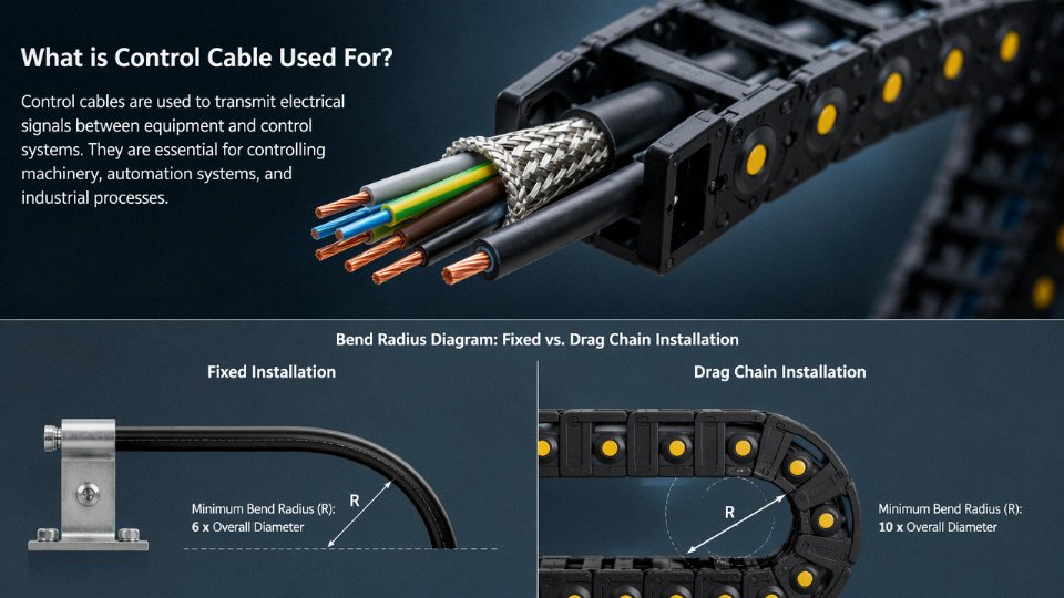
Fixed multi-core control cable installations require a minimum bend radius of 6× the cable’s overall outer diameter. Flexible control cable running in drag chains — increasingly common on CNC gantries and automated conveyor systems — needs 10–15× OD, with the higher end of that range applying to cables with foil-plus-braid shielding. Violate those limits and the consequences aren’t immediate; they’re cumulative. Insulation cracks at the stress point, shield foil fractures and loses continuity, and conductor fatigue sets in over thousands of flex cycles. By the time the fault shows up on a 4–20 mA loop, the cable has been failing slowly for months. IEC 61084 and individual manufacturer datasheets are your reference here — and it’s worth checking the datasheet because some constructions (particularly those with steel wire armor) carry tighter limits than the generic rule suggests.
Cable Tray Segregation: A Few Centimeters Can Save a Shutdown
IEC 61914 and NEC Article 800 both require separation between ELV control circuits and medium-voltage power cables. The working minimum is 200 mm of air gap between trays, or a continuous metallic separator plate if you’re constrained on racking space. This isn’t bureaucratic box-ticking. A 480 V power cable running parallel to an unshielded control cable over a 30-meter tray run can induce 50 Hz voltages of several hundred millivolts into a 4–20 mA analog circuit. That’s enough to make a flow transmitter read a consistent 0.5–1 mA high — which in a dosing application translates directly to a process quality problem or a safety deviation. Shielded cable mitigates this, but segregation is always the first line of defense. Shielding handles what segregation can’t fully eliminate.
Cable Glands: Fit Matters More Than Most Installers Realize
Match the gland IP rating (IP66 as a baseline for industrial enclosures, IP68 for submersible or wash-down environments), thread type (Metric, PG, or NPT depending on the enclosure standard), and — critically — the armor clamp design to the actual cable OD. Control cables of the same nominal cross-section vary in OD by ±1–2 mm across manufacturers; an undersized gland that lets the cable rotate will break the shield bond at the entry point and void the enclosure’s IP rating simultaneously. Both failures are invisible until something goes wrong.
Termination Quality: Ferrules Are Not Optional on Stranded Conductors
Every stranded control cable conductor entering a screw terminal or spring-clamp block should have a properly crimped bootlace ferrule. A 1.5 mm² conductor takes a 1.5 mm² ferrule — not a 2.5 mm² because it was the only box open on the bench. Bare wire insertions into spring-clamp terminals work fine on day one. Under sustained vibration from nearby motors or compressors, individual strands migrate, contact resistance climbs, and you end up chasing an intermittent fault that only shows up during production. That’s an expensive afternoon.
Ferrule crimping of stranded conductors before insertion into screw or spring-clamp terminals reduces intermittent contact failures caused by strand migration under vibration.True
This is consistent with IEC 60947-7-1 terminal block standards and widely documented in industrial wiring best practice guides; bootlace ferrules maintain a consolidated conductor cross-section and prevent individual strand displacement over time.
Shield Continuity and Insulation Testing Before Energization
Before a single circuit goes live, run two quick tests. First, a low-resistance ohmmeter check end-to-end on every shield drain wire — continuity should read under 5–10 Ω depending on cable length; a high or open reading means the shield was nicked or crushed during pulling. Second, insulation resistance testing at 500 V DC per IEC 60364-6, with an acceptable minimum of 1 MΩ between any conductor and shield, and between conductors. These take maybe 20 minutes per cable run and will catch installation damage before it becomes a control system mystery six months later.
Preventive Maintenance Over a 20-Year Service Life
Annual infrared thermography scans on loaded cable trays are worth scheduling — overloaded cores in a tightly bundled multi-core cable show up as localized hot spots well before insulation failure. Every five years, repeat insulation resistance testing on cables in harsh environments: chemical plants, outdoor exposed runs in tropical climates, anywhere with aggressive temperature cycling. Any cable showing visible sheath cracking, armor corrosion, or gland seal deterioration should be flagged for immediate replacement rather than monitored further; the cost of a replacement cable run is trivial compared to an unplanned process shutdown. Keep as-built cable schedules updated with route photographs. The engineer who installed the cable won’t be there in year 15, and a photograph of how a run passes through a conduit bank is worth more than any unlabeled single-line drawing.
Frequently Asked Questions About Control Cable
Can control cable be used as power cable in an emergency?
Physically, yes — a 2.5 mm² core can carry modest current. In practice, no, and you should not do it even as a short-term workaround. Control cables are not subjected to the short-circuit withstand tests or thermal endurance cycling that power cable insulation must pass under IEC 60364. The insulation walls are thinner, the thermal class is different, and a sustained overload that a proper power cable would survive can cause insulation softening, inter-core arcing, or outright fire in a multi-core control cable where heat has nowhere to dissipate. Beyond the physical risk, using control cable on a power circuit is a code violation that will fail any insurance or third-party audit. If you are genuinely in a breakdown situation and need a temporary feed, use the right cable rated for the load and document it — don’t reach for the nearest drum on the rack.
What is the maximum run length before voltage drop or signal degradation matters?
It depends heavily on signal type and cross-section. For a 24 V DC discrete signal with a 100 mA load, the formula is straightforward: voltage drop = 2 × length (m) × current (A) ÷ (conductivity × cross-section mm²). For 1.5 mm² copper (conductivity roughly 56 m/Ω·mm²), you can push around 500 meters before drop exceeds 10% — which is the practical threshold most PLC input cards will tolerate. For 4–20 mA analog loops, 1,000 meters is achievable with 0.75 mm² copper, but shielding becomes non-negotiable beyond about 100 meters in any environment with variable-speed drives, welding equipment, or medium-voltage switchgear nearby. Longer runs with low cross-sections and no shielding are one of the more common causes of mysterious instrumentation drift that people spend days chasing.
How do I identify a control cable on-site when the labels are gone?
Start with the jacket. Legitimate cable carries a printed legend showing voltage rating, core count × cross-section, and the standard reference — look along the length in good lighting. If the print has worn off, a cable identifier tone generator paired with a probe is the fastest method in a live panel. Cross-reference the as-built cable schedule; if that document doesn’t exist or hasn’t been maintained, that’s a separate problem worth fixing. Physically, control cables are recognizable by having many small cores relative to the overall diameter — a 19-core × 1.0 mm² cable looks very different from a 3-core power cable of similar OD.
LSZH versus standard PVC — when does the price premium make sense?
LSZH cable typically costs 20–40% more depending on order volume and conductor count. In a fire, standard PVC sheathing can release up to roughly 28% HCl acid gas concentration; LSZH holds that below 0.5% under IEC 60754-1/-2 test conditions. In a tunnel, a confined plant room, or a data center, that acid gas doesn’t just harm people — it destroys energized electronics and corrodes structural steel within minutes, turning a cable fire into a facility-wide equipment loss event. The relevant compliance markers to verify are EN 50575 Class Cca or higher and IEC 60754-1/-2 test reports from an accredited lab.
LSZH control cable produces less than 0.5% HCl acid gas concentration in fire tests per IEC 60754-1/-2, compared to up to 28% for standard PVC insulation.True
This figure is consistent with published IEC 60754-1/-2 test methodology and widely referenced in fire safety engineering literature for cable selection in confined or occupied spaces.
Specify LSZH any time the cable runs through areas with restricted ventilation, occupied buildings, or where equipment replacement cost after a fire event would far exceed the cable premium.
What core count and cross-section for a 16-output PLC remote I/O panel?
Work through it step by step. Sixteen digital outputs need a common return conductor, so that’s 17 cores minimum. Add 10–20% spare capacity for future I/O expansion or fault-finding flexibility, and you land at 19-core or 24-core. At 24 V DC with 0.5 A per output, voltage drop over a 50-meter run in 0.75 mm² stays within acceptable limits, but 1.0 mm² gives you headroom and is barely more expensive at that core count. A practical specification for most plants: 19-core × 1.0 mm² shielded, or 24-core × 0.75 mm² shielded if you want the spare cores and can live with slightly tighter drop margins.
How should cable drums be stored before installation?
Store drums upright on their flanges — never flat on their face. Flat storage crushes the lower layers and causes permanent deformation in the cable geometry that you won’t see until you’re fighting kinks during pull-in. Keep drums under cover, away from direct UV, away from ozone sources (electric motors idling nearby generate more ozone than most people realize), and away from any solvent or chemical storage. Ambient temperature between roughly –5°C and +40°C is the working range; below that, PVC becomes brittle and should not be unreeled without a warming period. Use a proper drum stand with a spindle and always pay the cable off the top of the drum — pulling from the side creates twists that you cannot easily remove once the cable is in conduit.
What distinguishes Jinda control cable from generic alternatives?
Jinda has been producing cable since 1987 across five manufacturing bases in China, with the full production chain from wire drawing through finished cable under one roof. That vertical integration matters for quality consistency — raw material testing happens in-house before anything reaches the line, not just on spot-check batches. Products are manufactured to IEC 60227, IEC 60502, and VDE standards, with export documentation available for projects in 50+ countries. For procurement teams working on larger projects, Jinda’s technical team can review cable schedules, provide samples ahead of bulk orders, and configure non-standard core counts or insulation variants rather than forcing a standard catalog item onto an application it doesn’t quite fit.
Why Sourcing Control Cable from a Verified Manufacturer Matters for Long-Term Project Risk
The cable itself is rarely the biggest line item in a project budget. That’s exactly why it gets underspecified, sourced on price alone, or bought from a distributor who can’t answer basic questions about where it was made. And that’s exactly where long-term cost gets destroyed.
The Real Cost of Substandard Cable Isn’t the Cable Price
Insulation degradation and premature sheath cracking account for somewhere between 15% and 25% of unplanned shutdowns in process industries — that range comes from failure analysis studies cited in audit reports by bodies like Intertek and Bureau Veritas, and the actual figure at any given plant depends heavily on cable age, thermal cycling severity, and whether the original specification was honest. The cable purchase price is not the exposure. The exposure is what happens next.
Replacing a failed buried armored control cable run in a chemical plant — trench excavation, confined-space permitting, decommissioning the circuit, pulling new cable, re-terminating, recommissioning, and the production loss sitting on top of all of that — typically runs 50 to 100 times the original cable cost. I’ve seen figures quoted at the lower end for short, accessible runs in relatively simple facilities, and well past the upper end when the trench crosses process pipework or the failure happens mid-shutdown when contractor rates are punishing. The cable that saved your project $800 on a $12,000 order can cost you $600,000 to fix.
Four Supply Chain Risks That Don’t Show Up on the Datasheet
Buyers sourcing from unverified suppliers face a specific, documented set of failure modes — not hypothetical ones.
Falsified test certificates are a recurring problem in the global cable market, well-documented in third-party auditor findings. A certificate showing conformity to IEC 60227 or IEC 60502 means nothing if the lab named on it didn’t actually perform the tests, or if the certificate belongs to a different production batch entirely.
Conductor undersizing is measurable and surprisingly common. Instances of nominal 1.5 mm² cable delivered at actual cross-sections of 1.2 mm² or below have been recorded in market surveillance programs. At 1.2 mm² you’re running 25% higher resistance than the circuit was designed for — higher voltage drop, more heat, shorter insulation life, and a protection device that may not operate when you need it.
Substandard PVC compound is harder to detect on arrival. Insufficient plasticizer content produces a sheath that looks fine at acceptance, then cracks within two to four years in outdoor or thermally cycled environments rather than the 20-year service life a proper compound delivers.
Inconsistent outer diameter — sometimes varying by 0.5 mm or more across a production run — prevents reliable cable gland sealing. In wet or dusty environments that’s an ingress path straight to the termination.
Minimum Supplier Qualification Criteria for Any Serious Project
For any cable procurement above roughly USD 50,000 in total value, the minimum documentation a qualified supplier should provide without hesitation: full batch traceability from copper rod to finished drum; spark test pass logs and conductor resistance measurements from production (not just type tests); third-party type test reports from an accredited independent laboratory; and a standing factory audit invitation. If a supplier hedges on any of these, that’s the answer.
Jinda's production facilities are certified to ISO 9001:2015 and operate across five manufacturing bases in Shandong covering 470,000 m² of production space.True
This is stated manufacturer information consistent with the company profile and verifiable through audit. ISO 9001:2015 certification is a documented quality management system requirement, not a product performance claim.
Vertical Integration as a Quality Control Mechanism
Jinda’s five production bases in Shandong, operating across that 470,000 m² footprint, run copper rod drawing through final jacketing under one quality management system. That vertical integration matters practically, not just on a capabilities slide. When the compound supplier, the drawing mill, and the extrusion line are all inside the same audit perimeter, material substitution without documentation is harder to do and easier to catch. Consistent outer diameters, consistent insulation thickness, consistent compound formulation across a multi-drum order — these are manufacturing discipline outcomes, and they’re what prevent the gland sealing failures and early cracking described above.
For buyers facing copper commodity price volatility — and anyone who sourced cable in the past few years knows how violent that volatility can be — fixed-price framework agreements with a manufacturer who controls raw material input provide real budget protection. Reserved drum inventory programs serve a different but related risk: peak demand periods, particularly in the March-to-June construction season and again in Q4, routinely produce 8 to 14 week lead time stretches from traders who don’t hold stock. A reserved inventory arrangement converts that risk into a known delivery schedule.
Jinda’s application engineering team also reviews cable schedules before production begins — free of charge, on projects of meaningful scale. In practice this catches specification errors that would otherwise result in either a non-conformance on site or an over-engineered cable that inflated the BOM unnecessarily. Neither outcome is good. Catching it before the drum is wound is the only efficient fix.