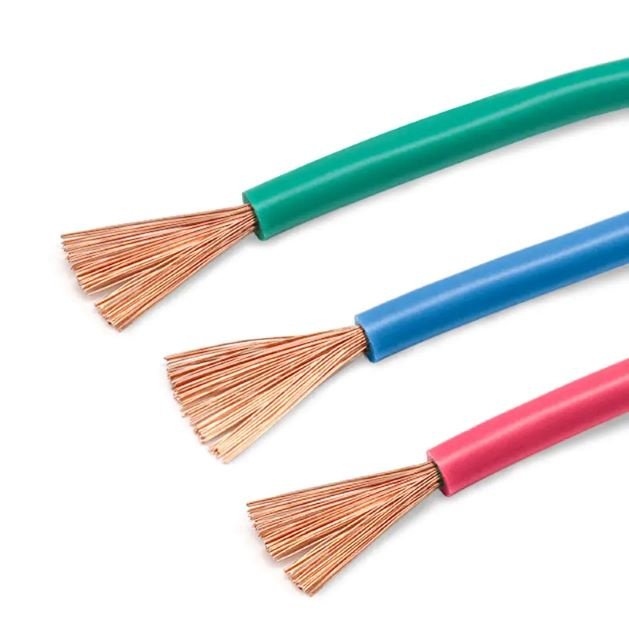
Misidentify a cable as “close enough” and you don’t always get a fire — sometimes you just get intermittent faults that take a maintenance crew three shifts to chase down, or insulation that cracks after one winter cycle and starts tracking moisture into a control panel. Either way, the plant pays: unplanned downtime, scrapped product, accelerated equipment wear, and the kind of corrective procurement that costs 30–40% more than planned buying. Getting industrial wiring right from the specification stage is the only way to avoid that cycle.
Industrial wiring refers to the conductors, insulation systems, protective jackets, and associated hardware used to distribute power and control signals within manufacturing facilities, processing plants, and industrial machinery. It spans conductor sizes from roughly 14 AWG (2.5 mm²) up to 750 kcmil (380 mm²), must meet standards such as NFPA 79 or IEC 60204-1, and is engineered to handle voltages from 600 V into the tens of kilovolts while surviving temperature extremes, mechanical stress, and chemical exposure that would destroy commercial-grade cable in months.
What makes industrial wiring a genuinely distinct discipline — not just heavier-gauge building wire — is how tightly the physical environment dictates every specification decision. The right cable in a food-processing washdown area is wrong inside a steel mill’s cable tray, and both of those are wrong routed next to a variable-frequency drive. That interdependency is what this article works through.
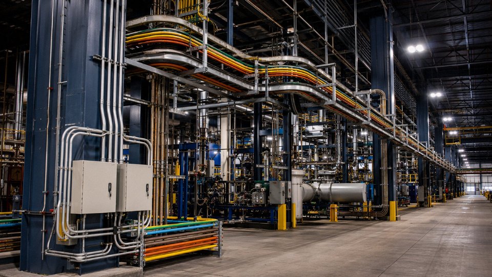
Core Components That Make Up an Industrial Wiring System
Every industrial wiring system is an assembly of interdependent physical elements, and specifying one without understanding the others is how procurement mistakes happen. Here is what you are actually buying.
Conductors and Cable Cores
Bare annealed copper dominates power cables in most fixed plant installations — it’s cost-effective and bonds well under compression lugs. Tinned copper becomes the better choice in marine environments, high-humidity food-processing areas, or anywhere sulfur-bearing atmospheres accelerate oxidation; the tin layer adds maybe 15–25% to conductor cost but can triple service life in those conditions. Aluminum shows up in larger feeder runs, typically 2/0 AWG (67 mm²) and above, where the weight and cost savings justify the extra torque discipline at terminations and the need for anti-oxidant compound.
Stranding class matters more than most specs sheets acknowledge. Class 1 solid conductors work fine in conduit runs that will never move. Class 2 compressed stranding is the standard workaround for most panel wiring and cable trays. Go to Class 5 or Class 6 fine-strand flexible conductors for machine tool wiring, drag chains, and any application with repeated flexing — a Class 2 conductor in a continuous flex application will work-harden and fracture at the termination within a year or two, sometimes faster depending on bend radius and cycle rate.
Insulation Materials
XLPE (cross-linked polyethylene) handles up to 90°C continuous in most ratings and offers excellent dielectric strength — typically 20–30 kV/mm depending on compound formulation — along with good resistance to oils and many solvents. It’s the default choice for medium-voltage power cables in the 5–35 kV range. EPR (ethylene propylene rubber) runs at similar temperatures but is more flexible at low temperatures and maintains better dielectric properties in wet or partially submerged conditions, which is why you see it specified for nuclear, offshore, and underground mining applications.
PVC is everywhere because it’s cheap and self-extinguishing, but above roughly 70°C it softens, and in a fire it releases hydrogen chloride — a serious concern in enclosed areas. LSZH compounds were developed specifically for tunnels, rail, data centers, and any space where evacuation is difficult; smoke density and halogen content are the metrics that matter there, not just flame spread. Thermoplastic elastomers (TPE, TPU) occupy a useful middle ground: better flexibility than PVC at low temperatures, good abrasion resistance, and cleaner combustion profiles, though at a noticeable cost premium.
Shielding and Armoring
For control and instrumentation cables, foil shields (aluminum-polyester laminate) give complete 100% coverage and are fine for static or low-flexing runs. Braided copper shields — typically 85–95% optical coverage — handle flex better and provide lower impedance ground paths, which matters in variable-frequency drive installations where high-frequency noise is the actual problem.
On the mechanical protection side, steel wire armor (SWA) handles direct burial and areas with potential impact or rodent damage. Steel tape armor (STA) costs less but offers less crush resistance; it’s appropriate for cable tray or duct installations where the primary concern is incidental contact. North American MC (metal-clad) cable uses interlocked aluminum armor — it’s not equivalent to SWA and shouldn’t be substituted in applications requiring the latter.
LSZH cables produce significantly less toxic smoke than standard PVC cables in fire conditionsTrue
LSZH compounds are formulated to restrict halogen content below 0.5% HCl emission by weight and limit smoke density; this is verified under IEC 60754 and IEC 61034, which are standard test requirements for LSZH qualification.
Raceways and Containment
Rigid metal conduit (RMC) is the hardest, most protection-intensive option — it’s required in many hazardous locations and wherever physical damage is a realistic risk. EMT (electrical metallic tubing) works in dry indoor environments and is far easier to bend and install, though it shouldn’t be used in wet locations or embedded in concrete without verification against local code. Cable trays are the workhorse of large industrial plants; ladder tray keeps cables cooler and is easier to inspect, while solid-bottom tray protects against dripping liquids. Flexible liquid-tight conduit is essential at motor terminations and any equipment that vibrates or requires periodic repositioning — the liquid-tight rating matters in wash-down or outdoor zones.
Termination Hardware
Compression lugs, done right with the correct die and tool, are the most reliable terminations in industrial service. Mechanical connectors are acceptable for smaller conductors but require re-torquing checks on a schedule, especially near heat sources where thermal cycling loosens fasteners. Terminal blocks in panels should be rated for the fault current and wire range you’re actually using — undersized blocks are a common source of resistance heating that shows up on thermal imaging during maintenance rounds but often gets ignored until it fails.
Overcurrent and Protective Devices
Industrial-rated molded-case circuit breakers and fused disconnects are sized to interrupt fault currents that can reach 65–100 kA in heavy facilities, well beyond what a residential panel device can handle. Motor circuit protectors (MCPs) are specifically calibrated for motor inrush and should not be replaced with standard breakers of the same ampere rating — the trip curves are fundamentally different. Ground fault protection relays in industrial panels are typically set to trip at 5–30 A ground fault current, much higher than the 6 mA threshold in GFCI devices for personnel protection; the industrial threshold is about protecting equipment, not people directly.
Identification and Labeling
IEC 60445 and NEC Article 310 define color conventions that differ between regions — brown/black/grey for line conductors under IEC versus black/red/blue in older US three-phase practice. Heat-shrink wire markers with printed legends hold up in environments where adhesive labels peel off within months. In a well-documented plant, every conductor has a unique identifier that ties back to the panel schedule and the wiring diagram; in a poorly documented one, every fault-finding exercise costs an extra two to four hours of tracing time. That’s the operational argument for doing it right on installation day.
Industrial Wiring Standards and Codes That Govern Design and Installation
Standards aren’t paperwork. Get them wrong and you’re looking at failed inspections, insurance voids, or — in a hazardous location — something far worse. Here’s how the global landscape actually breaks down.
NFPA 70 (National Electrical Code) — The U.S. Baseline
The NEC is the foundational document for electrical installations across the United States, adopted by most states with local amendments. For industrial wiring specifically, four clusters of articles do the heavy lifting.
Article 300 covers wiring methods — conduit fill, separation requirements, burial depths, and protection against physical damage. Article 310 governs conductor ampacity, insulation types, and correction factors for ambient temperature and conduit bundling; this is where you size your cables, not just pick a wire that “looks big enough.” Article 430 is the motor article and it’s dense — it handles branch circuit sizing, overload protection, disconnecting means, and control wiring for motor controllers, which together account for a significant share of the wiring in most production facilities. Articles 500 through 516 cover hazardous locations using the Class and Division system: Class I (flammable gases/vapors), Class II (combustible dusts), Class III (fibers), each divided into Division 1 (normally present) and Division 2 (present only under abnormal conditions). Misclassify a Division 1 space as Division 2 and you’ve specified the wrong enclosure rating — that’s a real failure mode in older plant expansions.
NFPA 79 — Machine-Level Wiring
NFPA 79 is the standard that many automation engineers live inside. It governs electrical equipment on industrial machinery — think CNC machining centers, injection molding presses, automated assembly lines. Conductor color coding under NFPA 79 is specific: green or green/yellow stripe for protective earth (PE), white or gray for neutral, and black for ungrounded conductors in AC circuits. Minimum conductor size for machine control circuits is generally 14 AWG (2.5 mm²), though low-energy logic circuits can go smaller with justification. The standard also mandates a readily accessible disconnecting means at the machine, lockable in the open position — something that’s audited closely during OSHA inspections.
IEC 60204-1 — The International Counterpart
Across Europe, most of Asia, and export markets generally, IEC 60204-1 performs a parallel function to NFPA 79. The two standards have been deliberately harmonized over successive revision cycles, so the overall philosophy is similar: supply disconnection, protective bonding, control circuit requirements. Differences do exist. IEC 60204-1 uses the Zone-based hazardous area system (Zone 0, 1, 2 for gases; Zone 20, 21, 22 for dusts) rather than the NEC Class/Division framework, and color coding follows IEC convention — blue for neutral is standard, while the green/yellow PE requirement is consistent with NEC. Conductor cross-sections are specified in mm² per IEC 60228, rather than AWG.
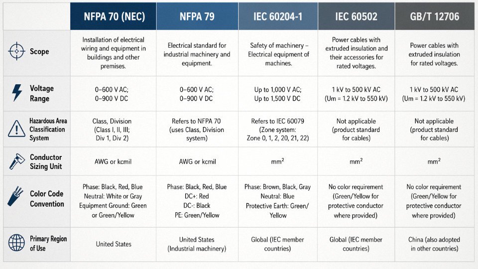
IEC 60502 covers the construction of power cables from 1 kV up to 30 kV, specifying insulation materials, sheathing, and test requirements. If you’re sourcing medium-voltage cable for a substation feed or a long plant run, this is the construction standard your supplier’s product should reference.
GB/T Standards — What Chinese-Sourced Cable Actually Cites
Buyers sourcing from Chinese manufacturers will encounter GB/T 12706 for medium-voltage power cables. GB/T 12706 is closely aligned with IEC 60502 — China adopted IEC as the reference basis when the standard was last revised — but there are detail-level differences in type approval testing sequences and some material specifications. In practice, reputable manufacturers produce to both standards simultaneously and can supply test reports under either. Ask specifically for IEC-basis test reports if your project requires it; a certificate citing only GB/T may not satisfy a European or Middle Eastern owner’s engineer.
Jinda cables are certified to IEC 60502, IEC 60228, and GB/T 12706, with test reports available under both IEC and GB/T frameworks for international procurement.True
Jinda operates five production bases in China with integrated R&D and quality systems, producing cables for customers across more than 50 countries; dual-standard certification is standard practice for export-oriented Chinese cable manufacturers serving international EPC contractors.
Hazardous Location Certifications — ATEX, IECEx, and NEC Class/Division
The two global systems for hazardous area equipment certification — ATEX (European Union directive) and IECEx (international scheme administered by IEC) — both use Zone classification and require equipment to carry a certification mark from a notified or recognized body. NEC Class/Division certification in North America is handled through UL listing or FM approval. These systems are not automatically interchangeable. An ATEX-certified cable gland is not automatically acceptable on an IECEx project, and neither is automatically compliant with NEC without separate listing. For oil and gas, chemical processing, and grain handling applications, verify the specific certification scheme required by the project specification before ordering — substituting one for another is a common and costly mistake.
CE, UL, and CSA — What to Check on a Certificate of Conformity
A certificate of conformity should state the specific standard (with revision year), the certifying body’s accreditation number, the cable type and construction it covers, and any limitations on scope (voltage rating, temperature range, installation method). UL listing confirms compliance with UL standards through ongoing factory surveillance — it’s not a one-time test. CSA covers Canada and is accepted in many U.S. jurisdictions alongside UL. CE marking on cables indicates self-declaration against the Low Voltage Directive or CPR (Construction Products Regulation) in the EU, depending on the application. Ask your supplier which applies and request the declaration of conformity, not just the CE logo on a data sheet.
Industrial Wiring Cable Types Classified by Application and Environment
Getting the cable type wrong is usually where industrial electrical projects start bleeding money — through premature insulation failure, nuisance tripping, or, in the worst cases, a cable fire inside a conduit bundle that nobody can isolate quickly. The taxonomy below is organized by application and environment, which is how engineers actually make decisions on the floor.
Power Cables for Fixed Installation
In North American plants, THWN-2 and XHHW-2 are the workhorses for branch circuit and feeder runs up to 600 V. Both handle 90°C in wet or dry locations; XHHW-2 is the more rugged choice in conduit runs exposed to coolant splash or outdoor raceways. Sizing follows NEC ampacity tables with derating for conduit fill — a bundle of six or more current-carrying conductors in a hot conduit in a foundry environment can push derating factors past 0.5, which catches people off guard.
Internationally, the IEC 60502-1 standard governs 0.6/1 kV power cables with XLPE insulation, steel wire armor (SWA), and PVC oversheath. These are direct-buried under plant roadways, pulled through cable ladders, or installed in underground ducting between transformer bays and motor control centers. Conductor sizing here runs from roughly 1.5 mm² up to 300 mm² or larger depending on fault current requirements and ambient soil temperature.
Medium-Voltage Plant Distribution
Once you cross into 5 kV–35 kV territory — substation feeds, long inter-building runs, utility interconnections — you need screened, XLPE-insulated, armored construction. The metallic screen handles capacitive charging current and provides a fault return path; without it at these voltages, you’re looking at insulation breakdown that doesn’t announce itself until something fails catastrophically.
XLPE insulation outperforms EPR at temperatures above 90°C for most MV plant distribution applicationsTrue
XLPE has a rated maximum conductor temperature of 90°C continuous (105°C emergency) and lower dielectric losses than EPR in typical utility-frequency plant distribution, though EPR remains preferred in wet, highly flexible, or high-cycling applications such as trailing cables.
Jinda’s 35 kV cable product range covers this space for international procurement — XLPE insulation with copper wire screen and double steel wire armor for direct burial or tray installation, relevant to projects in petrochemical, mining, and heavy manufacturing where the substation is not adjacent to the load.
Flexible Trailing Cables for Mobile Machinery
Mining trailing cables, crane festoon cables, and welding cables all share one design requirement: the conductor has to survive bending, not just carry current. High strand counts — sometimes 1,500-plus fine copper strands per core — combined with rubber jackets (EPR or neoprene, depending on oil resistance needs) give these cables endurance ratings in the range of hundreds of thousands of flex cycles. A standard THWN wire in the same application will work for a few months before the conductors start fracturing at the bend point. Welding cables specifically run 100% stranded bare copper under a natural or synthetic rubber jacket, rated to handle the high short-duration currents (easily 200–400 A on a stick welder) without thermal damage.
Control and Instrumentation Cables
PLC panel wiring, field instrument loops, and thermocouple runs need shielding — but the type of shielding matters. Individually shielded pairs (ISP) isolate each signal from adjacent channels; overall shield (OS) designs only block external interference. For analog 4–20 mA loops and low-level millivolt signals, ISP with a drain wire is the standard choice. Low-capacitance constructions (typically targeting under 50–60 pF/m, though this varies by conductor gauge and dielectric material) reduce signal attenuation on long runs. A 300-meter run of high-capacitance cable to a pressure transmitter can round off fast transient signals enough to confuse a DCS.
VFD Cables
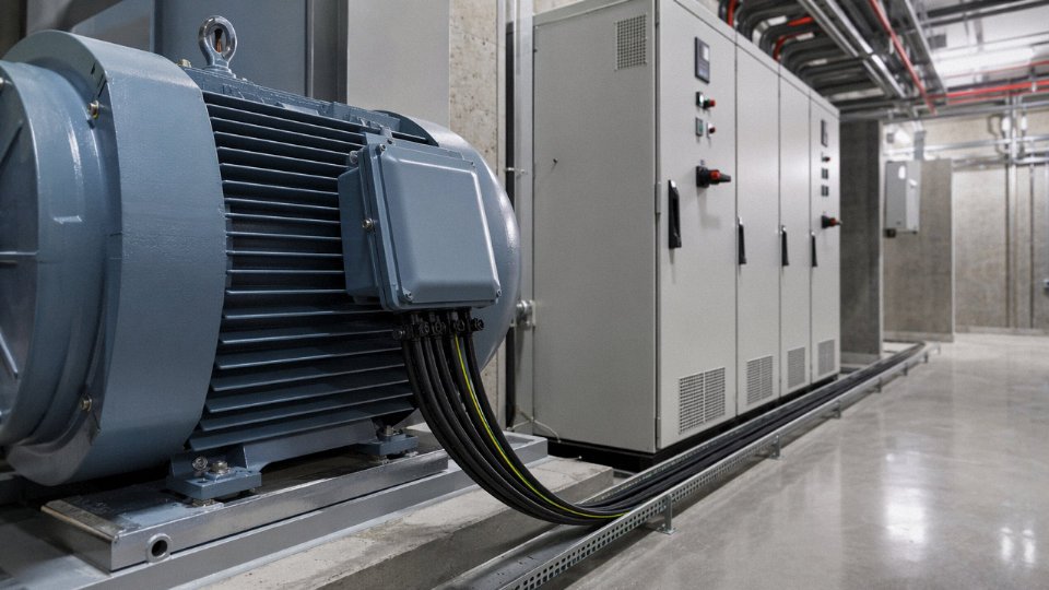
This is the category most often misspecified. Standard power cable installed on a VFD output run develops reflected wave voltages at the motor terminals — pulses that can double the drive’s output voltage at the motor, especially on runs over roughly 15–30 meters depending on cable capacitance and drive switching frequency. Common-mode currents travelling back through asymmetric ground paths also induce bearing currents that pit motor bearings within a year in some cases.
A proper VFD-rated cable uses three symmetrically arranged phase conductors, three symmetrically placed ground conductors (not a single ground in a random position), and a 100% foil-plus-braid shield with full 360° termination at both ends. The symmetrical geometry keeps common-mode impedance balanced and gives the high-frequency return current a low-impedance path that doesn’t go through the motor bearing. Using a standard armored power cable here instead will technically run the motor — but usually not for long without bearing or winding damage.
Fire-Resistant and Fire-Alarm Cables
IEC 60331 and BS 6387 set the baseline for circuit integrity cables — the ones that have to keep the evacuation alarm, emergency lighting, or fire pump running while the building is on fire around them. BS 6387 CWZ classification is demanding: the cable must survive fire, water spray during firefighting, and mechanical shock simultaneously. LSZH (Low Smoke Zero Halogen) jackets are essentially mandatory in enclosed spaces — control rooms, tunnels, offshore platforms — because PVC gives off hydrogen chloride under combustion, which is toxic at low concentrations and corrodes switchgear.
Specialty Industrial Cables
A few types that don’t fit neatly elsewhere but appear regularly on plant BOMs: thermocouple extension cables matched to specific alloy pairs (Type K, J, T) to avoid introducing parasitic EMFs; self-regulating heating cables for pipe freeze protection, where resistance changes with temperature automatically; continuous-flex robotic cables for robot arms with torsion and bending cycles in the millions, typically featuring fine-strand tinned copper, specialized polymer jackets, and helically wound tape layers to prevent core migration; and direct-burial armored cables for perimeter security runs or cross-plant underground feeders where mechanical protection from dig-ins is the primary concern.
Each of these is a specification in its own right. Treating them as interchangeable with general-purpose cable is the kind of decision that shows up as a warranty claim or an unplanned shutdown six months after commissioning.
Industrial Wiring Installation Methods, Routing Practices, and Separation Requirements
Getting the cable spec right is only half the job. A perfectly rated conductor installed sloppily — overstuffed conduit, mixed signal and power trays, no sealing fittings at a hazardous-area boundary — will fail prematurely or create a code violation that shuts down commissioning. Installation method matters as much as the wire itself.
Conduit Fill and Why the 40% Rule Exists
NEC Chapter 9, Table 1 limits conductor fill to 40% of a conduit’s internal cross-sectional area for three or more conductors. The number isn’t arbitrary. Conductors generate heat under load, and a tightly packed conduit acts as an insulating sleeve around them — heat builds, insulation softens, derating becomes necessary, and in a worst case you get an accelerated aging failure that’s nearly impossible to trace back to the fill violation years later.
The calculation sequence: find the actual cross-sectional area of each conductor including insulation (NEC Chapter 9, Table 5 or Table 5A for compact conductors), sum them, then check the result against the conduit’s permitted fill area (Chapter 9, Table 4). Where cable types are mixed — say, THHN control wires alongside XHHW power conductors — use the actual outside diameter for each, not a generic assumption. In practice, procurement often orders the same diameter for all conductors to simplify the calculation, which is sensible when you’re pulling 20+ circuits through a long conduit run.
Cable Tray: Ladder, Ventilated Trough, and Solid Bottom
Ladder tray is the default choice in most heavy industrial plants for power cables 10 mm² and above — good ventilation, easy inspection, straightforward cable additions during future modifications. Ventilated trough works well for smaller control cables where you need some mechanical containment without the airflow penalty of solid bottom. Solid-bottom tray is typically reserved for data or instrumentation runs where physical protection from dropped hardware matters more than heat dissipation.
Support spacing runs up to about 1.5 m maximum under IEC 60364 and most plant engineering standards, though the actual interval depends on tray span load ratings and the weight of filled cables — a tray loaded with 95 mm² armored cables hits its span limit much sooner than one carrying 2.5 mm² control wiring. Bundled cables in tray require derating per IEC 60364-5-52 Table B.52.20; once you stack more than roughly 6–9 single-layer cables, the grouping factor drops to 0.7 or below depending on installation method, which directly affects what conductor cross-section you need to size.
Segregation: Power, Signal, and Data in the Same Building
The 300 mm minimum separation between power cables (600 V and below) and instrumentation or signal cables running in parallel is a reasonable starting point, but it’s a minimum, not a comfortable margin. In plants with variable-frequency drives or large motor feeders, induced noise on parallel signal cables can corrupt 4–20 mA loops even at 300 mm if the run extends beyond 10–15 m. Crossing at 90° is far preferable to parallel routing wherever layout allows.
Medium-voltage cables (above 1 kV) should be physically separated from low-voltage systems by tray tier, barrier, or routing path — not just distance. The EMI argument is secondary here; the primary concern is fault energy containment.
A minimum 300 mm separation between power and signal cables in parallel runs is sufficient to prevent electromagnetic interference in all industrial environments.False
300 mm is a commonly cited minimum, but it is not universally sufficient. Longer parallel runs, high-current VFD feeders, and sensitive instrumentation circuits often require greater separation, 90-degree crossings, shielded cable, or separate enclosed raceways to reliably prevent coupling and noise on signal circuits.
Hazardous Area Wiring Methods
Zone classification drives the method, and mixing them up creates a life-safety problem.
Zone 0 (continuous explosive atmosphere) is restricted almost entirely to intrinsically safe (Ex i) circuits — low-energy instrumentation loops that cannot generate a spark capable of ignition even under fault conditions. Zone 1 installations typically use explosion-proof (Ex d) enclosures with sealed conduit systems; sealing fittings must be installed within 450 mm of any Ex d enclosure entry and wherever conduit transitions to a non-hazardous area. Zone 2 permits increased-safety (Ex e) terminations and, in some cases, standard industrial wiring methods with appropriate enclosure ratings. Skipping a sealing fitting to save time during construction is one of the more common installation shortcuts — and one of the more consequential ones during an incident investigation.
Underground and Outdoor Routing
Direct burial depth requirements vary by voltage class and jurisdiction, but typical guidance is 600 mm minimum cover for LV cables (up to 1 kV) and 900 mm for medium voltage under most IEC- and NEC-aligned codes. Duct bank design adds concrete encasement, pull boxes at intervals no longer than roughly 90–120 m depending on cable weight and bend radius, and manholes at all direction changes. In chemically active soils — near fertilizer plants, wastewater treatment facilities, coastal areas with saline groundwater — bare steel wire armor corrodes faster than most engineers expect. Aluminum-sheathed cables or HDPE-jacketed armored designs are worth specifying from the outset rather than discovering the corrosion problem during a 5-year inspection.
Vibration Zones and Mechanical Protection
At panel and junction box entries on vibrating equipment — conveyors, compressors, mills — flexible conduit length should stay between 450 mm and 600 mm. Too short and the fitting absorbs no movement; too long and it sags, collects moisture, and eventually chafes. Liquidtight flexible metal conduit (LFMC) is standard in most wet or oily industrial environments. Stress-relief clamps at panel entries prevent cable weight from working the termination loose over months of vibration. On mobile equipment (cranes, transfer cars, process robots), cable anchor intervals typically run 300–500 mm on the fixed end, transitioning to a managed loop or festoon system for the travel section.
Labeling, Color-Coding, and Documentation
IEC 60445 defines conductor identification conventions — green/yellow for protective earth, blue for neutral, and brown/black/grey for line conductors in three-phase systems. NFPA 79 requires that every industrial machine conductor be identified at each termination point. In practice, plants that skip this during installation spend the next decade guessing which wire is which during every maintenance outage.
As-built documentation should capture conduit/tray routing, fill levels, cable schedule with conductor IDs, and hazardous-area classification boundaries. It is the record a maintenance technician references at 2 AM during an unplanned shutdown — and it needs to reflect what was actually installed, not what the design drawings originally showed.
Sizing Industrial Wiring Correctly: Ampacity, Voltage Drop, and Short-Circuit Withstand
Getting the wire size right is where industrial cable engineering actually earns its keep. A lookup table can get you close; it cannot get you compliant, efficient, and fault-safe simultaneously. Real sizing works across three dimensions — ampacity, voltage drop, and short-circuit withstand — and you have to satisfy all three before you finalize a conductor cross-section.
Ampacity: The Starting Point, Not the Finish Line
Ampacity is the continuous current a conductor can carry without exceeding its insulation’s rated temperature. IEC 60364-5-52 and NEC Table 310.15 both publish base ratings, but those base values assume specific reference conditions — typically 30°C ambient for IEC, 40°C for NEC. Real plants are rarely that cooperative.
Two correction factors do the most damage in hot or congested installations. The ambient temperature factor k_t reduces rated current when the surrounding air is warmer than the reference — in a foundry or a tropical compressor room running at 50°C, you might apply a k_t of roughly 0.82 on a 90°C-rated XLPE conductor. The grouping or bundling factor k_g is where engineers most often underestimate derating: six loaded cables touching in a tray can push k_g down to 0.57 or lower, depending on arrangement and tray fill. Multiply those factors together and your 95 mm² conductor is suddenly doing the work of something considerably smaller. Thermal insulation scenarios — cables buried under pipe lagging or passing through insulated panels — demand their own correction, often dropping effective ampacity by 30–50%.
Motor Circuits Deserve Their Own Treatment
Motor branch circuits under NEC 430.22 and IEC 60204-1 clause 12.5 are sized at a minimum of 125% of the motor’s full-load amperage, not 100%. This is not conservatism for its own sake. Motors run continuously at or near full load, and the 1.25 multiplier accounts for that sustained thermal stress.
Starting current is a separate concern. Across-the-line starters pull 6–8× full-load amps for anywhere from a fraction of a second to several seconds depending on load inertia. That transient does not require you to upsize the conductor for thermal reasons — the thermal time constant of a copper conductor is long enough that short starts don’t accumulate dangerous heat — but it does affect the short-circuit protection coordination upstream, which feeds back into your conductor selection logic.
Voltage Drop: Where the Formula Actually Matters
The full single-phase formula is V_drop = I × (R·cosφ + X·sinφ) × 2L. For three-phase, replace the 2L factor with √3 × L. At low frequencies and shorter runs, reactance X is often minor and engineers simplify to I × R × 2L, which is reasonable for most MCC-to-motor runs below 100 m. Beyond that, ignoring X introduces real error.
Acceptable limits in industrial practice: 3% maximum on individual branch circuits, 5% total from service entrance to load. Exceed those and you’ll see motors running hot, contactors dropping out at low voltage, and VFD fault trips that look like drive problems but are actually supply quality issues.
A worked example keeps this concrete. Say you have a 75 kW, 400 V three-phase motor drawing roughly 138 A full-load, located 150 m from the MCC. Assume power factor 0.85, a 95 mm² copper XLPE conductor with resistance around 0.193 Ω/km at operating temperature. Voltage drop calculates to approximately 2 × 150 m × 138 A × 0.000193 Ω/m × 0.85 ≈ 6.8 V per phase — about 1.7%, which clears the 3% limit. Drop to 50 mm² and you’re over 3% on that run alone. That’s before any upstream impedance is added.
Short-Circuit Withstand: The Adiabatic Check
Every conductor must survive a bolted fault long enough for protection to clear it. The adiabatic equation is S = I_sc × √t / k, where S is the minimum cross-section in mm², I_sc is prospective fault current in amps, t is the clearing time in seconds, and k is a material/insulation constant. For copper conductors with XLPE insulation, k = 143. With PVC insulation, k = 115.
If your MCC feeds from a 25 kA fault level and the upstream breaker clears in 0.2 s, a 95 mm² copper XLPE conductor gives you a withstand capacity of roughly 143 × 95 / √0.2 ≈ — wait, the formula inverts: S_min = (I_sc × √t) / k = (25,000 × √0.2) / 143 ≈ 78 mm². So 95 mm² clears that check comfortably. Specify 50 mm² and you’re asking the insulation to absorb energy it cannot handle — the result is insulation carbonization, a damaged cable that may pass initial inspection but fail catastrophically under load weeks later.
Copper XLPE conductors use k=143 in the IEC adiabatic short-circuit withstand calculation, while copper PVC conductors use k=115.True
These k values are defined in IEC 60364-5-54 and IEC 60909 supporting standards; XLPE's higher thermal limit allows it to absorb more fault energy per unit cross-section than PVC.
Harmonic Loading and the Neutral Nobody Sizes Correctly
Facilities running large populations of variable frequency drives, switch-mode power supplies, or rectifier-fed equipment carry significant 3rd-harmonic (triplen) currents. In three-phase four-wire systems, triplen harmonics do not cancel in the neutral — they add. In a heavily loaded VFD environment, the neutral can carry 1.73× the phase conductor current. Sizing the neutral identically to the phase conductors, which is standard practice in clean power systems, results in an overloaded and potentially overheated neutral that standard overcurrent protection won’t catch.
The correct response is to specify a neutral conductor sized at 173% of the phase conductor cross-section, or to use dedicated harmonic-rated cables where the neutral is already oversized from the factory. Skipping this step is one of the more common root causes of mysterious panel heat and nuisance tripping in modern automated plants.
The Four-Step Sizing Workflow
Load schedule first — establish continuous and peak currents for every circuit. Then select for ampacity, applying k_t and k_g corrections honestly. Verify voltage drop over actual cable runs, especially for motors located far from the MCC. Finally, run the adiabatic check against the available fault current and protection clearing time. All four steps. In that order.
In practice, the voltage drop check most often drives a conductor upsize; the short-circuit check occasionally forces a further increase on high-fault-current buses. It’s rare that a conductor sized purely for ampacity ends up being the final answer.
Jinda’s technical support team works through this four-step process directly with procurement managers and project engineers on bulk orders — providing cable selection recommendations, run-specific voltage drop analysis, and short-circuit withstand confirmation against the customer’s actual protection coordination data. For international projects where the design team is working across multiple standards simultaneously, that kind of application support tends to prevent the expensive cable re-pulls that happen when sizing is left to the contractor’s discretion.
Industrial Wiring in Hazardous and Demanding Environments: Chemical, Mining, Oil and Gas
Cable selection errors in routine commercial buildings usually mean a callback and a code violation. In a chemical plant, an offshore platform, or a gassy mine, the same mistake can mean a fire, an explosion, or a fatality. These environments aren’t just “more demanding” — they impose fundamentally different specification logic, and the cables that work fine in a motor control center inside a clean factory will fail badly here.
Chemical and Petrochemical Plants
The primary jacket threat in a chemical plant isn’t heat — it’s continuous low-level chemical exposure that quietly degrades standard materials over 18–36 months. PVC, which is perfectly serviceable in dry industrial buildings, absorbs aromatic hydrocarbons and many chlorinated solvents over time. The plasticizers leach out, the jacket stiffens and cracks, and you end up with exposed conductors in exactly the environment where you cannot have them.
CSPE (Hypalon) resists a broad range of acids, oils, and ozone and has a long track record in chemical service — typical operating range is roughly -40°C to +90°C, depending on the specific formulation. CPE jackets offer similar chemical resistance at a lower cost and are easier to extrude in high fill-rate production, though they’re generally considered slightly inferior to CSPE in prolonged ozone and UV exposure. Cross-linked LSZH compounds have gained ground where fire toxicity is also a concern — enclosed chemical processing buildings where smoke evacuation is poor — but you have to verify chemical compatibility for the specific jacket compound, because “LSZH” is a fire behavior classification, not a chemical resistance specification. That distinction trips up procurement teams fairly regularly.
Oil and Gas Offshore Platforms
Offshore work introduces a combination of requirements that no single-environment cable standard fully addresses. IEC 60092-350 governs shipboard and offshore electrical installations, and cables qualified to this standard must pass flame propagation, smoke density, and halogen emission tests appropriate for enclosed marine spaces where evacuation is constrained. Mechanically, cables in offshore tray systems deal with something you don’t see onshore: continuous wave-induced vibration. On a floating production platform, cable trays flex slightly and constantly. Cables need adequate armoring — typically steel wire armor or aluminum wire armor — and the armor terminations need proper mechanical clamping, not just standard glands. Mud-resistant outer sheaths matter for drilling deck wiring, where water-based and oil-based drilling fluids contact cable surfaces routinely.
Mining Trailing Cables
A trailing cable on a continuous miner sees more mechanical abuse per operating hour than almost any other cable in industry. It’s dragged across rock floors, run over by shuttle cars, and flexed through tight radii repeatedly throughout a shift. Conductor stranding must be fine enough to survive this — rope-lay or bunched stranding with a high strand count — and the jacket compound needs abrasion resistance alongside flexibility.
In gassy mines (methane-bearing coal seams, primarily), IEC 60079 and MSHA regulations both apply, depending on jurisdiction. Ground fault monitoring is mandatory in most mining electrical codes; the cable design must accommodate the monitoring conductors as an integral part of the assembly.
Standard PVC-jacketed power cables are not suitable for continuous use in methane-rated mining environmentsTrue
MSHA and IEC 60079 require cables in gassy mine environments to meet flame-retardant and antistatic specifications that standard PVC compounds do not satisfy; dedicated trailing cable constructions with approved jacket materials are mandated
Food, Beverage, and Pharmaceutical Plants
Washdown zones require wiring systems designed around the cleaning process, not just the electrical load. Stainless steel conduit (316L where chlorinated cleaning agents are used) resists the pitting that carbon steel develops after repeated chlorine exposure. Conduit fittings should be IP69K-rated — that rating specifically covers high-pressure, high-temperature water jets, which is exactly what sanitary washdown uses. LSZH insulation makes sense here partly for fire toxicity and partly because some standard PVC compounds can harbor bacteria in surface micro-cracks.
Color-coding in pharmaceutical plants sometimes follows internal hygiene-zone protocols that go beyond NEC or IEC color conventions. If you’re supplying cable to a pharma project, confirm the plant’s internal color standard before ordering — finding out at termination that your blue cables mean something different in that facility’s zone scheme is an avoidable problem.
High-Temperature Environments
Steel mills and glass furnaces push ambient temperatures well beyond the range of most polymer insulations. Silicone rubber insulation handles continuous service to around 180°C and retains flexibility at low temperatures too, which matters in plants where cables run from a hot furnace area through an unheated outdoor section. For applications requiring continuous operation above 250°C — thermocouple extension wiring near furnace elements, for instance — mineral insulated (MI) cable is essentially the only viable option. MI cable is expensive and labor-intensive to terminate properly, but it’s inert and essentially indefinite in service life when correctly installed. Mica-taped fire-resistant cables fill the middle range, providing circuit integrity during fire events without the installation difficulty of MI.
Outdoor Utility-Scale Installations
Solar farm DC string wiring operates in conditions that destroy standard cables within a few years: UV radiation, ground contact or proximity, wide daily temperature cycling, and in many regions, rodent activity. UV-stabilized XLPE jackets rated to TÜV 2PfG 1169 (the PV cable standard) or equivalent are the baseline. The transition point from DC string wiring to the AC collection network — typically at the inverter or combiner box — marks a shift to medium-voltage XLPE armored cable, often direct-buried. Wind turbine tower cables have their own requirement set: continuous flexing as the nacelle yaws, torsional stress, and sometimes very cold ambient temperatures that rule out materials with poor low-temperature flexibility.
Jinda’s production lines cover flame-retardant (FR), fire-resistant (FRC), LSZH, armored, and medium-voltage cable ranges, with manufacturing certifications including IEC, CE, and MSHA-relevant testing that maps directly to the sectors above. When a procurement manager is sourcing for a project that spans, say, an offshore gas processing platform and its onshore pipeline terminal, having a single qualified supplier for both the marine-rated IEC 60092 cables and the direct-burial armored MV feeders onshore significantly reduces qualification overhead and supply-chain complexity.
Common Industrial Wiring Failures, How to Detect Them, and Prevention Best Practices
Wiring failures rarely announce themselves dramatically. Usually they accumulate — a slightly warm termination box, a sporadic PLC input error, an insulation resistance reading that’s drifted down from 800 MΩ to 40 MΩ over three years. By the time something trips or burns, the damage has been progressing for months. Understanding the failure modes, and having a maintenance protocol that catches them early, is what separates a plant that runs at 95% uptime from one that doesn’t.
Insulation Degradation from Thermal Overload
Thermal degradation is probably the most common failure mode on production floors running older equipment. The visual symptoms — tan or brown discoloration on PVC jackets near motor terminations, surface cracking along cable runs near heat sources — are often dismissed as cosmetic. They’re not. Those are signs that the polymer chain in the insulation has broken down irreversibly.
Root cause is almost always one of two things: persistent overloads that nobody bothered to derate for, or cables routed through areas hotter than their rated temperature class. A cable rated to 75°C derated incorrectly for a 40°C ambient conduit bank can easily run 10–15°C above its design limit for years.
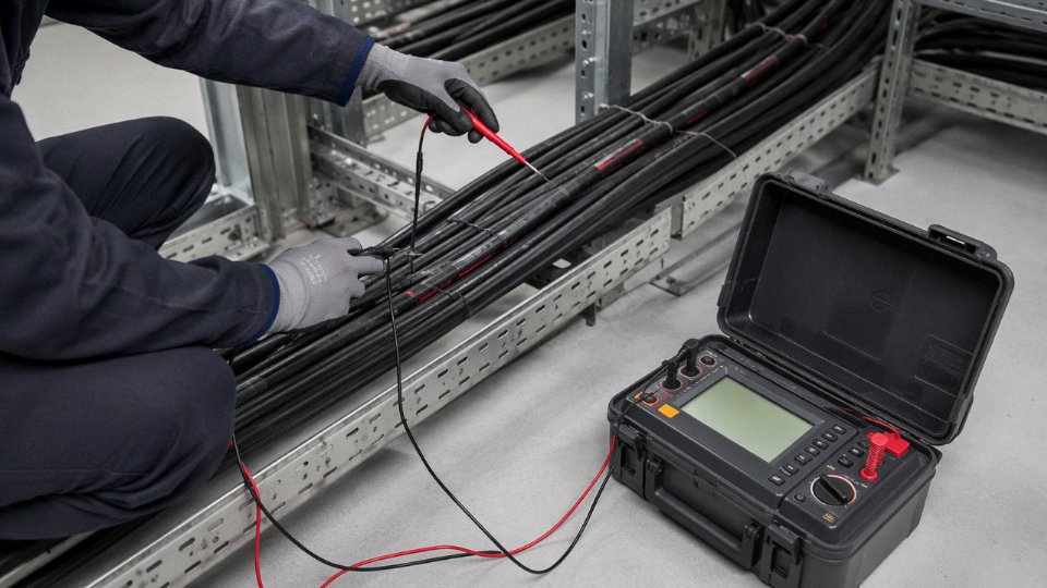
Insulation resistance (IR) testing with a Megger at 500 V DC for low-voltage circuits, or 1,000 V DC for medium-voltage feeders, gives you a quantitative baseline. Healthy cable on a new installation should read well above 100 MΩ·km; anything trending below 10 MΩ·km warrants investigation, and below 1 MΩ·km is a replacement conversation. Test annually, record the values, and trend them — a single low reading is less informative than watching the slope of decline over three years.
Mechanical Damage: Abrasion, Crush, and Flex Fatigue
Cable trays without proper edge protection, or with sharp burrs left from field-cut tray sections, abrade jacket and armor over time through vibration alone. Armored cables generally require a minimum bend radius of 6–10× the cable OD depending on armor type — steel wire armor sits toward the higher end of that range. Violating bend radius during installation creates stress concentrations in the conductor stranding that eventually fatigue-crack, especially on cables feeding reciprocating equipment.
Flex cables for continuous-movement applications — cable tracks on CNC machines, overhead cranes, robotic arms — need to be specified as flexible from the outset. Standard fixed-installation cable will fail at the flexing point within months. This is a purchasing error more than an installation error, and it’s worth catching at the BOM stage.
Connection and Termination Failures
Loose compression lugs and undertorqued terminations are responsible for a disproportionate share of switchgear fires. A loose connection introduces resistance; resistance generates heat; heat accelerates oxidation; oxidation increases resistance further — the cycle runs until something fails or an IR camera catches it first. Aluminum terminations are especially vulnerable because aluminum oxide forms quickly and has poor conductivity.
Every manufacturer publishes torque specifications for their lugs and terminal blocks. In practice these are often ignored after initial installation. An annual retorque program on motor terminal boxes and main distribution panels, particularly in high-vibration environments, costs very little in labor and prevents a significant share of termination failures.
Thermographic (infrared) inspection of energized switchgear terminations can detect resistive heating before it causes failureTrue
IR cameras detect elevated temperature at loose or corroded connections under load, which is an established predictive maintenance technique documented in NETA maintenance standards and widely used in industrial facilities.
Moisture Ingress and the Wicking Problem
Stranded conductors wick moisture. If a cable end is exposed — even briefly, during installation — capillary action draws water longitudinally through the stranding and into panels or junction boxes meters away. On a coastal chemical plant or in a humid food processing environment, this happens faster than most people expect.
The fix is specified at procurement, not after installation: water-blocking tape or gel-filled interstices in the conductor assembly, sealed conduit entry fittings (Appleton or equivalent), and proper end caps on cables stored in the field. A cable with no water-blocking spec costs marginally less; the cost of panel corrosion and unplanned downtime is considerably higher.
EMI and Shield Grounding
Unshielded instrumentation cables running parallel to power feeders in the same tray are a reliable recipe for erratic PLC inputs and false sensor readings. The fix isn’t always a full reroute — sometimes it’s simply specifying shielded twisted-pair cable and grounding the shield correctly. Single-point grounding at the control panel end, with the field end floating, is the standard approach. Grounding both ends creates a ground loop that can make EMI problems worse rather than better.
Predictive Maintenance Tools Worth Using
For medium-voltage cable systems, partial discharge testing identifies insulation voids and contamination before they become tracking faults. Time-domain reflectometry (TDR) locates impedance discontinuities in long cable runs — useful when you have a fault somewhere in a 500-meter buried feeder and need to excavate as little as possible. Thermographic inspection of switchgear, combined with annual IR testing, covers most of what you need for a defensible predictive maintenance program.
The Lifecycle Cost Argument for Correct Specification
A correctly specified cable — right insulation class, appropriate armor, rated for the actual service temperature — realistically lasts 25–35 years in a typical industrial installation. An undersized or thermally mismatched cable in the same environment may require replacement in 7–10 years, and that replacement carries not just material cost but installation labor, production downtime, and potentially hazardous materials disposal. Over a 30-year plant life, the total cost difference between correct and marginal specification, depending on the system size and access difficulty, can run to multiples of the original cable cost. Specifying correctly at procurement is the cheapest maintenance decision you will ever make.
How to Specify and Procure Industrial Wiring for Large-Scale Projects
Procurement failures on large industrial cable projects almost never happen because someone chose the wrong voltage rating. They happen because the specification was vague, the cable schedule was incomplete, and the supplier quoted something subtly different from what the engineer intended. Getting this process disciplined upfront saves far more money than squeezing the unit price.
Building a Cable Schedule That Eliminates Ambiguity
A cable schedule is the master procurement document — a structured spreadsheet or database table where every cable in the project gets its own row: tag number, origin and destination, routed length plus a contingency allowance (typically 10–15% added for field offcuts and rerouting), conductor cross-section, number of cores, voltage rating, insulation material and temperature class, armor type, outer jacket, color coding scheme, applicable standard, and drum allocation. A complete schedule means a supplier in Shanghai can quote exactly what a project engineer in Rotterdam intended. Without it, you get five different interpretations from five different vendors, and the cheapest quote is usually the one that cut the most corners on specification.
Routed lengths deserve attention. Scale-drawing takeoffs routinely undercount vertical runs, cable tray bends, and the slack required at termination points. In practice, add at least 10% to drawing length for horizontal runs and closer to 20% for heavily congested vertical risers.
Writing a Cable Technical Specification
The Cable Technical Specification (CTS) is the companion document to the schedule — it defines how the cables must be built, not just what size they are. Key clauses to lock down: applicable standards (IEC 60502-1 for low-voltage power, IEC 60227 for light-duty control, NFPA 79 for machinery circuits in North American projects); conductor material, purity, and stranding class per IEC 60228 (Class 2 for fixed installation, Class 5 for flexible); insulation and jacket compound with explicit temperature rating — don’t just write “PVC,” specify whether it’s 70°C or 90°C rated, oil-resistant or standard; armor type (steel wire, steel tape, or aluminum wire depending on mechanical exposure); preferred drum lengths to minimize mid-run joints; and FAT requirements.
Drum length preferences matter more than buyers usually realize. Specifying non-standard lengths forces a manufacturer to cut from standard production drums and sell you remnants at a premium, or worse, to deliver short drums that create field splices exactly where you don’t want them.
Factory Acceptance Testing
For any critical project, the CTS should list required tests by reference to the standard, not just by name. Conductor resistance per IEC 60228, routine high-voltage withstand per IEC 60502-1 Table 6, insulation resistance measurement, and spark test continuity for low-voltage cables are the baseline. For projects in oil and gas or mining, specify third-party witness inspection — a representative from a body like Bureau Veritas or Intertek physically attends the test runs at the factory. This is not bureaucratic overhead; it catches compound substitutions and cross-section deviations before 20 tonnes of wrong cable ships to a remote site.
IEC 60502-1 requires routine high-voltage withstand testing on every manufactured length of power cable before dispatch from the factory.True
IEC 60502-1 Clause 15 mandates routine electrical tests, including high-voltage withstand, as a condition of product conformance for each drum length produced.
Evaluating Suppliers Beyond the Price Column
ISO 9001 certification is a floor, not a differentiator — check whether the supplier’s in-house laboratory is calibrated and traceable to national standards, and ask for raw material traceability records: copper rod mill certificates, insulation compound batch numbers, armor wire tensile test data. For multi-year contracts, financial stability matters too. A supplier that can’t fund raw material inventory during a copper price spike will delay your project.
Drum Packaging, Labeling, and Logistics
Standard wooden cable drums run from D630 for small-gauge control cable up to D2500 for large power cable. Container loading limits practical drum weight to roughly 2,500–3,000 kg depending on the container floor rating and forklift capacity at the destination port — heavier drums need flat-rack shipping, which adds cost. For export shipments using wooden drums, ISPM-15 phytosanitary heat treatment is mandatory in most importing countries; confirm this is included in the supplier’s scope, not an afterthought. Cable labeling on the drum flange should include cable tag, cross-section, drum length, gross weight, manufacturing date, and standard reference — all in the project’s required language.
Jinda’s five production bases across China allow order consolidation and container loading from the port most efficient for the destination region, which meaningfully reduces freight time for high-volume orders.
Total Cost of Ownership vs. Purchase Price
A 10–15% premium on cable quality is usually recovered within the installation phase alone. Better-stranded conductors terminate faster and more reliably, reducing labor hours per termination by a small but real margin across hundreds of connections. Cables built to tighter diameter tolerances fit conduit and cable tray fill calculations correctly, avoiding field rework. And cables that don’t fail prematurely don’t generate replacement costs, unplanned downtime, or insurance claims. Over a 20–25 year asset life, the total cost differential between mid-tier and bargain-tier cable is rarely close.
Long-Term Supply Partnership
For buyers running ongoing capital programs — multiple plant expansions, annual maintenance stock replenishment, international projects on rolling schedules — blanket purchase orders and consignment stock arrangements reduce both procurement overhead and lead-time risk. Jinda supports priority production scheduling for customers with committed annual volumes, which matters when copper prices spike and production slots tighten across the industry. The ability to call off stock against a standing order, rather than re-quoting each project from scratch, is the kind of operational simplicity that procurement managers actually value once they’ve lived through a supply disruption.
Frequently Asked Questions About Industrial Wiring
What is the difference between industrial wiring and commercial wiring?
The gap is larger than most people expect. Commercial wiring — offices, retail spaces, light assembly — typically operates at 120/208 V or 240/415 V, handles intermittent loads, and lives in a relatively clean, stable environment. Industrial wiring serves continuous heavy loads that can run 24 hours a day, voltages that in some plants reach 6.6 kV or 35 kV at the distribution level, and physical conditions that would destroy a standard commercial cable within weeks: cutting fluids, ammonia, radiant heat from furnaces, constant flexing on cable tracks, forklift impacts. The governing standards reflect this — NFPA 79 and IEC 60204-1 impose requirements on conductor sizing minimums, shielding, color coding, conduit fill, and grounding that simply don’t apply in a commercial context. In practice, the wrong assumption here costs money. A contractor who specs a commercial-grade THHN in a food-processing wet area will be pulling and replacing it inside 18 months.
Can I use standard NM (Romex) cable in an industrial facility?
No. NM cable is explicitly restricted to dry residential and light-commercial applications. Its PVC jacket and thermoplastic insulation aren’t rated for the mechanical abuse, chemical exposure, or sustained operating temperatures common in industrial settings. Most industrial jurisdictions require cables to be installed in metallic conduit, cable tray, or in armored/MC cable configurations — partly for physical protection, partly because industrial fault currents are high enough that a damaged jacket in a live environment is a serious arc-flash hazard. If someone on your team suggests NM to cut costs on a secondary control run, that’s a conversation worth having before the inspector shows up.
What does LSZH mean and when is it required?
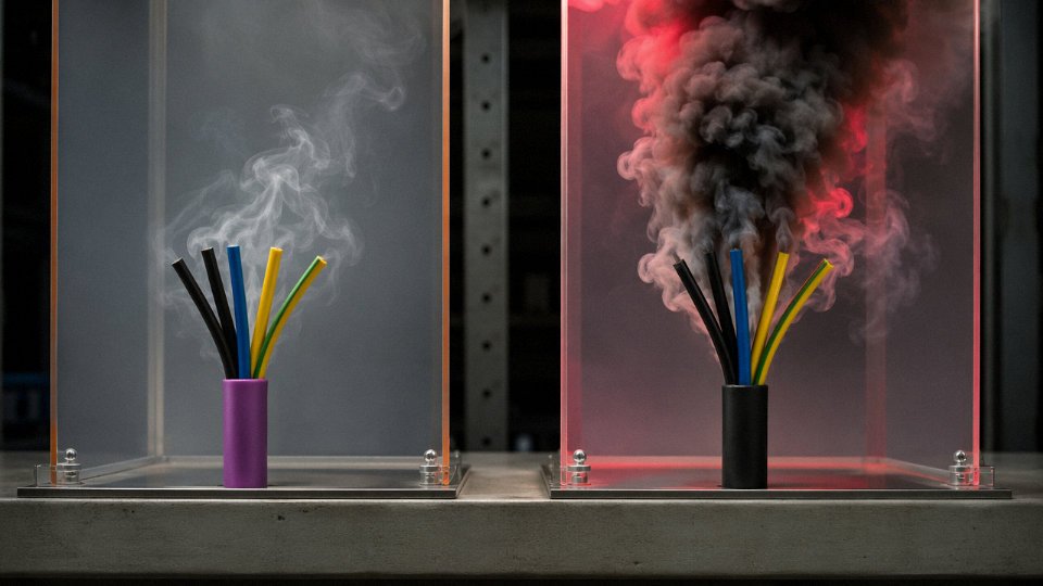
LSZH stands for Low Smoke Zero Halogen. When a standard PVC-jacketed cable burns, it releases hydrogen chloride gas and dense black smoke — both of which are more likely to kill people in a confined space than the fire itself. LSZH compounds are formulated to minimize smoke opacity and eliminate halogen acid gases during combustion. They’re typically mandatory in tunnels, offshore platforms, rail rolling stock, enclosed cable basements, and anywhere that delayed or obstructed evacuation is a real scenario. Some plant owners specify LSZH facility-wide simply to reduce liability and because the price premium over standard jacket compounds has narrowed considerably in recent years.
How often should industrial wiring be inspected and tested?
IEC 60364-6 covers initial verification and periodic inspection. For industrial premises, inspection intervals of roughly 1–3 years are typical, though the right interval depends heavily on environment severity, load cycling, and whether the installation sees any mechanical disturbance. A clean, climate-controlled control room can go longer; a cable run through a hot, vibrating machine gallery probably warrants annual visual inspection at minimum. Medium-voltage systems — 3.3 kV and above — often receive annual partial discharge monitoring because insulation degradation at those voltages can progress fast and fail catastrophically with almost no visible warning.
What cable is required for a VFD (variable frequency drive) application?
Standard power cable is a poor match for VFD output circuits. The drive’s PWM switching generates high-frequency voltage spikes and common-mode currents that, in an unshielded cable run, will radiate EMI across the panel, induce bearing currents in the motor, and erode motor winding insulation over time. A proper VFD cable uses symmetrical three-phase conductors, three symmetrically placed ground conductors (not a single drain wire), a 100% aluminum foil shield, and a minimum 85% coverage braided copper shield over that. The symmetrical geometry controls impedance and gives the shield an unbroken 360° return path for high-frequency current. Cable length matters too — reflected wave voltage stress increases with run length, and beyond roughly 30–50 meters (depending on drive and motor ratings) you’re looking at either a load reactor, a dV/dt filter, or both.
VFD-rated cables with symmetrical ground conductors and dual-layer shielding reduce motor bearing current damage and radiated EMI compared to standard power cable in variable frequency drive applications.True
The symmetrical three-ground-conductor geometry provides a low-impedance high-frequency return path that reduces common-mode current, which is the primary mechanism of electrical bearing erosion in VFD-driven motors. This is consistent with IEEE 1346 guidance and VFD manufacturer installation requirements.
What is the minimum conductor size for industrial control wiring?
Both NFPA 79 and IEC 60204-1 set 0.75 mm² (roughly 18 AWG) as the floor for control circuit conductors. Some signal wiring can go down to 0.5 mm² where it’s mechanically protected — inside a cable duct in a panel, for instance — but in a high-vibration environment like a press or a compressor skid, 0.5 mm² conductors work-harden at terminations and fail eventually. In my experience, most experienced panel builders default to 1.0 mm² for all control wiring just to avoid callbacks.
How does Jinda Special Cable Group support international industrial projects?
Jinda’s involvement starts earlier than most customers expect — the team can review cable schedules, assist with technical specification drafting, and flag compatibility issues before a purchase order is cut. Supply is certified to IEC, GB, and UL standards depending on the destination market, and factory acceptance testing is available for large or specification-critical orders. Drum packaging is coordinated for export compliance, which matters more than it sounds on multi-container orders. With 37 years of manufacturing experience and active supply relationships across 50-plus countries, Jinda also carries the institutional knowledge of what documentation, test reports, and labeling different import markets actually require — not just what the standard says they require, which is sometimes a different thing.