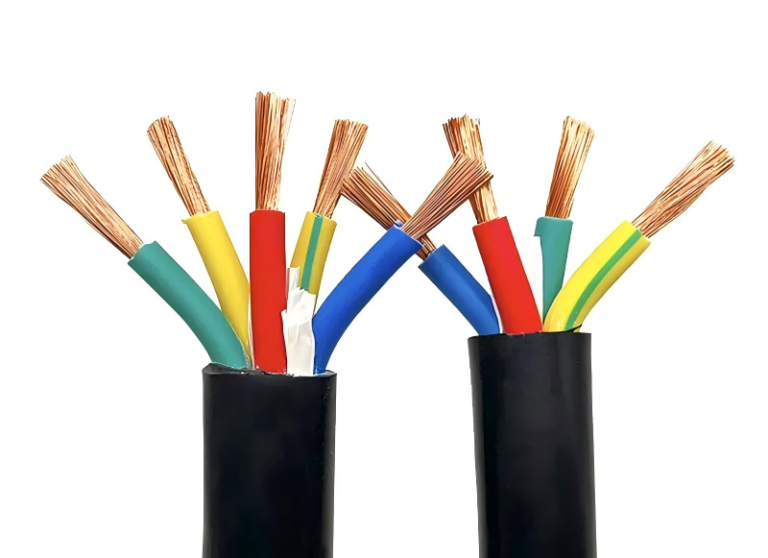
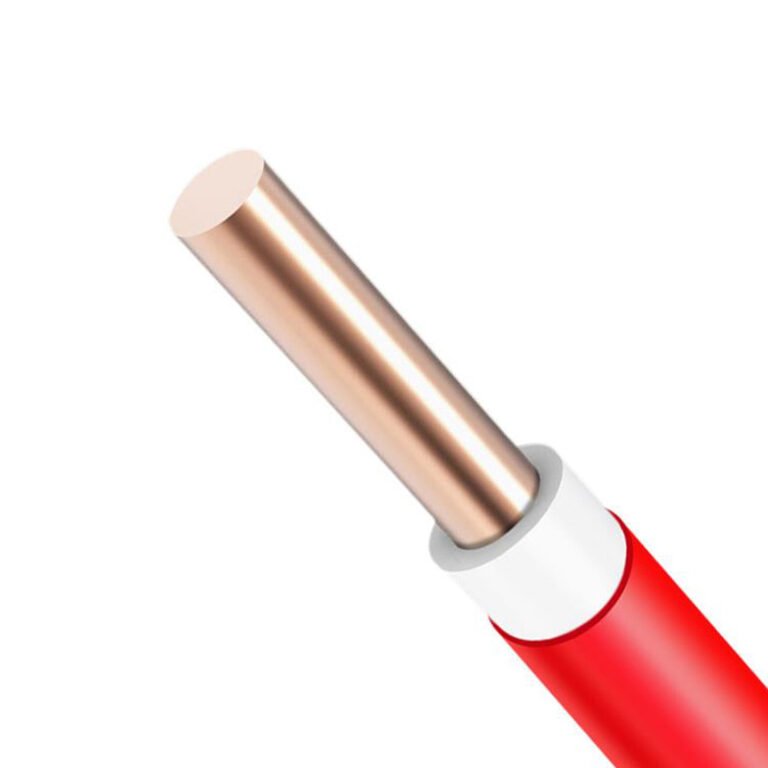
Flex cycles matter more than most procurement teams realize until a cable fails mid-shift. Strand a robot arm or a mobile welding carriage with a rigid conductor that was never rated for continuous bending, and you are not just looking at a replacement cable — you are looking at unplanned downtime, a scrap pile building up while maintenance hunts for the right spec, and expedite fees on a part that should have been right the first time. The fix is not exotic; it starts with understanding what conductor class you actually need, and why Type 3 flexible cable exists as a distinct product category.
A Type 3 cable is a flexible multi-conductor cable built around IEC 60228 Class 5 or Class 6 stranded conductors, designed for applications involving repeated movement, bending, or mechanical stress. Unlike fixed-wiring cables, its fine-wire strands — sometimes 189 or more per conductor — distribute bending strain across the cross-section, allowing the cable to survive 30,000 or more standardized flex cycles without conductor fatigue failure.
What makes this category genuinely interesting — and where engineers often get it wrong — is that “flexible” covers a surprisingly wide range of real-world demands. A drag-chain cable on a CNC gantry sees tight, repetitive bending every few seconds for years. A portable power lead on a construction site flexes occasionally but gets coiled, kinked, and run over. Both are called flexible. Both might be called Type 3. The conductor geometry, jacket compound, and lay length that keep one alive will quietly destroy the other.
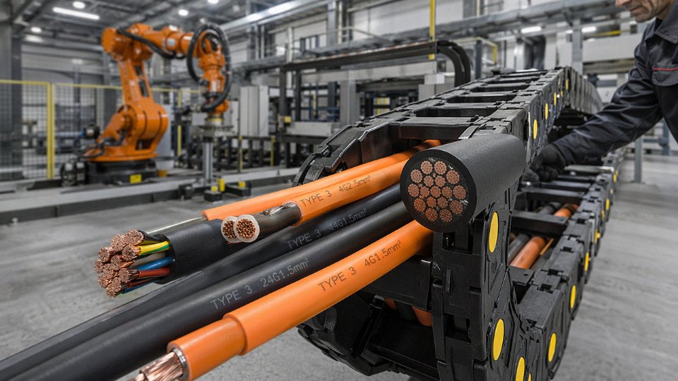
Type 3 Cable Construction: Conductors, Insulation Layers, and Jacket Materials Explained
The performance of a Type 3 cable under repeated flexing comes down almost entirely to how each layer is engineered — and whether those layers work together or fight each other during movement. A cable that looks adequate on a datasheet can fail in six months on a drag chain if the wrong insulation compound is paired with a stiff jacket. Here’s what each layer actually does.
Conductor Architecture: Why Strand Count and Wire Geometry Matter
The conductor is where most of the mechanical action happens. IEC 60228 Class 5 conductors use either bunched stranding (all wires twisted in one operation) or rope-lay construction (groups of smaller bundles twisted together), with fine annealed copper wire throughout. Annealing — a controlled heat treatment that relieves work-hardening — is non-negotiable here. Without it, repeated bending fatigues the copper quickly, and you start seeing broken strands inside intact insulation, which is the worst kind of failure because it’s invisible.
Typical strand counts for common cross-sections give you a practical feel for the difference between classes: a 1.5 mm² Class 5 conductor runs around 30 individual wires, while a 4 mm² conductor typically uses 56 wires. Step up to Class 6 and those numbers climb significantly — finer wires, more of them, and tighter geometric tolerances on each bundle. At 16 mm² and above, rope-lay construction becomes standard because you simply can’t bundle that many fine wires into a stable circle any other way.
Conductor Coating: Bare vs. Tin-Plated Copper
Bare annealed copper is fine for most dry indoor applications. Tin plating — a 1–3 µm electrodeposited layer — is specified whenever the cable will see sustained humidity, salt spray, or contact with sulfur-containing compounds. Marine cable runs, food-processing environments with cleaning chemicals, and battery-room wiring are the typical cases. The trade-off is a modest increase in contact resistance at the termination point, roughly 5–15% higher depending on connector type and plating thickness. In most power applications that difference is irrelevant. In low-voltage signal circuits it occasionally matters, so check before defaulting to tin-plated on instrumentation cable.
Insulation Compounds
Four materials cover the vast majority of Type 3 applications:
PVC is the workhorse — cheap, processable, available in a wide range of formulations, rated to 70°C continuous. Dielectric strength typically falls between 15–20 kV/mm depending on formulation and thickness. It becomes stiff below about -5°C to -10°C, which is worth remembering for outdoor installations in northern climates.
XLPE (cross-linked polyethylene) handles 90°C continuous and resists moisture absorption better than PVC. Dielectric strength is higher, usually 20–30 kV/mm, and the cross-linking means it retains shape under sustained load rather than creeping.
EPR (ethylene propylene rubber) is the preferred choice when low-temperature flexibility is the priority — it stays pliable down to roughly -40°C and tolerates mechanical abuse well. Common in offshore and mining cables.
Silicone rubber is a specialist material for static high-heat environments — rated 180°C and above, with excellent dielectric properties — but it tears relatively easily and doesn’t belong on anything that moves aggressively. Medical equipment and furnace wiring are the real use cases.
Shielding Options for Flexible Service
Braided copper shields provide good EMI attenuation (typically 85–98% coverage) and work fine in fixed or low-flex installations. In high-flex service — robot arms, continuous drag chains — braid wires fatigue at the crossover points and eventually break, degrading shield continuity. Spiral (serve) shields, where a single layer of copper wire is wound helically, flex far better because the wires don’t cross and lock against each other. The trade-off is slightly lower EMI attenuation. Wire armor (SWA) is almost never appropriate on true flexible cable; the steel wires resist bending, work-harden, and eventually crack the jacket from the inside.
Spiral (serve) shields outperform braided shields in continuous high-flex applications such as drag chains and robotic cable tracksTrue
Braided shield wires fatigue at crossover points under repeated flexing, causing intermittent shield breaks. Spiral-wound shields avoid crossover contact and maintain continuity through substantially more flex cycles, which is why IEC and major OEM specifications for trailing cables and energy-chain cables specify serve shields rather than braid.
Outer Jacket Materials
PVC jackets are cost-effective and adequate for light industrial use. Oil-resistant grades (often marked TM2 or similar per IEC 60811) tolerate incidental hydraulic fluid contact but not continuous immersion.
PUR (polyurethane) is the jacket material of choice for machine tool and drag-chain cable. It resists cutting abrasion better than PVC by a factor of roughly 3–8x depending on formulation, handles mineral oils well, and stays flexible at low temperatures. It costs more — plan for a 20–40% cable cost premium depending on jacket wall thickness and grade.
LSZH (low-smoke zero-halogen) is specified for enclosed public spaces, offshore platforms, and tunnel wiring where combustion byproducts are the primary hazard concern. It doesn’t resist abrasion or oils as well as PUR, so specifying it in a machine tool environment is usually a mistake.
EPDM rubber jackets handle UV, ozone, and weathering better than any of the thermoplastics. Used on outdoor trailing cables, mining equipment, and anywhere the cable is exposed to sunlight indefinitely.
Reference Table: Common Type 3 Sizes, Strand Counts, and Approximate Dimensions
| Cross-Section | Approx. Strand Count (Class 5) | Conductor OD (mm) | Typical Single-Core Jacket OD (mm) |
|---|---|---|---|
| 0.75 mm² | 24 | ~1.1 | 3.5–4.2 |
| 1.5 mm² | 30 | ~1.5 | 4.0–4.8 |
| 2.5 mm² | 50 | ~1.9 | 4.5–5.5 |
| 4 mm² | 56 | ~2.4 | 5.2–6.2 |
| 6 mm² | 84 | ~2.9 | 5.8–7.0 |
| 10 mm² | 80 | ~3.7 | 7.0–8.5 |
| 16 mm² | 126 | ~4.7 | 8.5–10.2 |
| 25 mm² | 196 | ~5.8 | 10.0–12.5 |
| 50 mm² | 396 | ~8.2 | 13.5–17.0 |
Dimensions are approximate and depend on insulation wall thickness, jacket compound, and manufacturer tolerances. Always verify against the specific product datasheet before designing conduit fill or cable tray layouts.
Type 3 vs. Type 1 and Type 2 Cables: Flexibility, Bend Radius, and Application Suitability Compared
The three flexibility types are not just catalog categories — they reflect fundamentally different conductor architectures, and mixing them up in a specification has real consequences on the plant floor.
How the Three Types Actually Differ
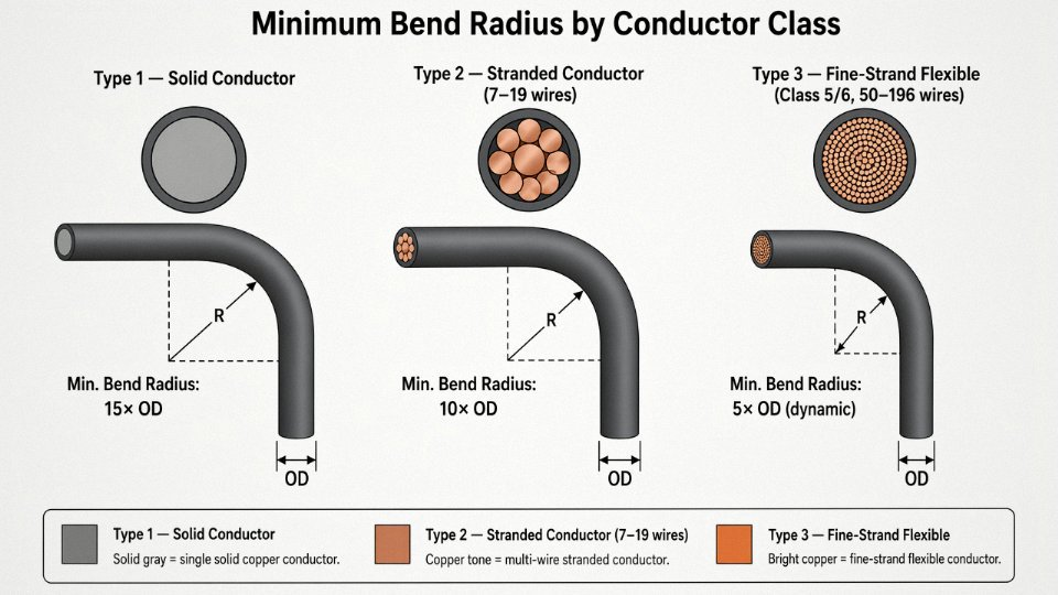
Type 1 uses a solid conductor: one wire per phase, no stranding at all. It’s stiff by design, meant to be pulled into conduit once and left there for decades. Type 2 moves up to a multi-strand construction — typically 7 to 19 wires bundled together — which makes it manageable enough to route through a control cabinet or reposition during a machine rebuild, but it was never engineered for repeated bending. Type 3 is a different animal entirely. The conductor is built from fine wires, often 50 to 189 individual strands depending on cross-section, twisted in a specific geometric pattern so the wire bundle can flex without individual wires work-hardening and fracturing. That distinction — fine-strand geometry versus merely “more than one wire” — is what separates a cable that lasts in a drag chain from one that fails in six months.
Bend Radius: Where the Numbers Actually Come From
Minimum bend radius is not arbitrary. It’s the tightest curve the cable can sustain without inducing plastic deformation in the conductor or cracking the insulation.
Solid Type 1 conductors typically require a static minimum bend radius of around 15× the cable’s outer diameter. Try to bend a 16 mm² solid conductor tighter than that and you’ll kink it — once kinked, the insulation is mechanically compromised even if it still passes a voltage test the next morning.
Type 2 stranded cable drops that to roughly 10× OD for occasional re-routing. That’s fine for panel wiring that gets repositioned during commissioning and then stays put.
Type 3 flexible cables — properly manufactured to IEC 60228 Class 5 or Class 6 — are rated for dynamic bend radii of 5× to 7.5× OD in drag-chain or cable-track service, and as low as 4× OD for hand-held portable equipment like power tools or extension leads. The actual figure depends on conductor cross-section, jacket compound, and whether the cable is specified for guided or unguided movement. A 2.5 mm² PUR-jacketed Type 3 cable behaves noticeably differently in a high-speed 5-meter drag chain than a 35 mm² version does.
Flex-Life Cycles: Concrete Benchmarks
IEC 60228 Class 5 Type 3 cables can survive 30,000 to 100,000 flex cycles depending on construction, versus fewer than 5,000 for solid Class 1 conductorsTrue
IEC 60228 and IEC 60811 test protocols confirm these figures; the wide Type 3 range reflects variables including strand count, pitch lay, jacket compound, and bend radius used during testing
In practical terms: a robotic welding arm cycling eight hours a day at 30 cycles per minute will accumulate roughly 14,400 flexes per shift. A Type 2 cable in that application is statistically likely to see conductor fatigue fractures within a few weeks. Type 1 would probably fail faster.
The Resistance Trade-Off
More strands means more wire-to-wire contact interfaces, and that pushes DC resistance up slightly compared to an equivalent solid conductor. For 1.5 mm² cross-section, a solid Class 1 conductor runs around 12.1 Ω/km; a Class 5 fine-strand conductor of the same nominal size sits closer to 13.3 Ω/km per IEC 60228 limits. That’s roughly a 10% increase. In a 10-meter machine tether carrying 10 A, the additional voltage drop is fractions of a volt — completely irrelevant. In a long power distribution run of several hundred meters feeding a sensitive load, it can start to matter, and an engineer should run the numbers rather than assume.
Application Suitability at a Glance
| Application | Type 1 | Type 2 | Type 3 |
|---|---|---|---|
| Fixed conduit wiring, building infrastructure | Correct choice | Acceptable | Overkill, higher cost |
| Control panel wiring, occasional repositioning | Poor — stiff, hard to dress | Correct choice | Works, minor cost premium |
| Machine tool tethers, drag-chain tracks | Do not use | Will fail — fatigue fracture | Correct choice |
| Robotic arm cables, continuous dynamic flex | Do not use | Do not use | Correct choice |
| Portable tools, extension leads | Do not use | Marginal, short service life | Correct choice |
Specification Mistakes That Actually Cost Money
The most common error I see in procurement specs is substituting Type 2 into a drag-chain application because the project engineer assumed “stranded” meant “flexible.” It doesn’t. Stranded just means not solid. A 7-wire Class 2 conductor has wire diameters three to four times larger than a 50-wire Class 5 conductor of the same cross-section, and those thick wires work-harden and snap under repeated bending just as solid wire does — only a bit more slowly.
Wrong minimum bend radius is another one. Specifying a Type 3 cable but mandating a 10× OD bend radius in the cable track installation drawing because “that’s what we use for everything” wastes most of the flexibility engineering that went into the cable. Conversely, forcing a PVC-jacketed Type 3 cable into a tight-radius drag chain in a cold environment — say, a food processing line running at 4°C — will crack the jacket within a season. PUR jacket is not optional in those conditions; it’s the difference between annual cable replacement and five-year service life.
International Standards and Approvals Governing Type 3 Flexible Cables
Specifying a flexible cable for a single plant is complicated enough. Specifying one that ships to Rotterdam, Houston, and Singapore in the same purchase order — while satisfying local inspectors at all three destinations — is where procurement teams genuinely earn their keep. The standards landscape is not chaotic, but it does require knowing which document governs the conductor, which governs the finished product, and which regional marking scheme your end customer’s safety inspector actually checks on arrival.
IEC 60228: Where the Conductor Classification Starts
Everything begins here. IEC 60228 defines conductor classes, and for Type 3 flexible cable the relevant classes are Class 5 (flexible) and Class 6 (extra-flexible). Class 5 conductors must survive a minimum of 30,000 standardized flex cycles — compare that to fewer than 5,000 for a Class 1 solid conductor, and you start to understand why using the wrong class in a drag-chain application costs you a cable replacement every few months rather than every few years. Class 6 pushes further still, with finer individual wire diameters and higher strand counts — sometimes 189 wires or more per conductor — primarily for welding leads, robotic arms, and similar high-cycle duty. Cross-sections covered run from 0.5 mm² up to 630 mm², though in practice most flexible cable procurement sits in the 1.5–95 mm² range. The specific upper limit depends heavily on the application: a portable generator set cable rarely exceeds 35–50 mm² per conductor, while a large offshore umbilical is a different conversation entirely.
IEC 60227 and IEC 60245: The Finished-Cable Product Standards
Once the conductor class is established, the finished cable is governed by either IEC 60227 (PVC-insulated) or IEC 60245 (rubber-insulated). Both cover voltage ratings at 300/500 V and 450/750 V, define the test methods for insulation resistance, voltage withstand, and aging, and — critically — assign the designation codes that should appear on the cable drum label and the purchase order. H05VV-F (light-duty PVC flexible, 300/500 V) and H07RN-F (heavy-duty rubber flexible, 450/750 V, natural rubber jacket) are the two you encounter most often in industrial settings. If a supplier quotes you a “flexible cable” without citing one of these designations, ask which standard their product actually complies with before the order ships.
Reading the HAR Marking System
In EU and EEA markets, cables manufactured to harmonized European standards carry the HAR mark — a small diamond logo stamped on the outer jacket at regular intervals, usually every metre. The designation code tells you everything: H07RN-F breaks down as H (harmonized), 07 (450/750 V rating), R (rubber insulation), N (natural rubber sheath), F (flexible conductor). A cable carrying a valid HAR mark is accepted across all EU member states without country-by-country re-testing. That is a meaningful procurement advantage; buying non-HAR cable and attempting to qualify it separately for Germany, France, and Poland simultaneously will cost you time you probably don’t have.
HAR-marked flexible cable meeting IEC 60245 is accepted across EU member states without additional national re-testingTrue
The HAR marking scheme, administered by CENELEC, is a multilateral agreement among national electrotechnical committees that grants mutual recognition of conformity testing results across all participating member states.
North American Equivalents: NEC Article 400, UL 62, and SOOW
The US and Canadian markets do not use IEC designations. Under NFPA 70 (NEC), flexible cables fall under Article 400, with UL 62 covering rubber-insulated flexible cord specifically. The cable designations you encounter are SOOW (600 V, oil-resistant, outdoor-rated) and SJOOW (300 V, junior service). These are functionally comparable to a Class 5 flexible rubber cable under IEC 60245, though the test protocols differ enough that a HAR-marked H07RN-F cable cannot simply be relabeled as SOOW for a US job site. If your project spans both markets, specify both — dual-listed cable exists but carries a cost premium of roughly 15–30% over single-standard product, depending on conductor size and order volume.
Marine and Offshore: IEC 60092, DNV, Lloyd’s, and Bureau Veritas
Shipboard and offshore platform installations add another layer. IEC 60092-350 covers general construction and test requirements for shipboard electrical cables; IEC 60092-376 addresses specifically the flexible cables used in those environments. Beyond the IEC baseline, class society type approvals — DNV GL, Lloyd’s Register, Bureau Veritas — impose additional requirements for flame propagation (IEC 60332 bunched-cable testing), smoke density, and halogen emission. Low-smoke halogen-free (LSZH) sheathing is often mandatory. A flexible cable that passes IEC 60245 perfectly may still fail a DNV type approval if it hasn’t been tested to these supplementary criteria. Always confirm class society approval status before quoting for offshore or marine tenders; the paperwork gap between “compliant with IEC” and “type-approved by Lloyd’s” has delayed more than one offshore project.
GB Standards and Dual-Compliance for Export
China’s GB/T 5023 (PVC flexible cables) and GB/T 5013 (rubber flexible cables) align closely with their IEC counterparts — the technical requirements are largely harmonized, which simplifies dual-compliant production. Jinda’s five production bases manufacture to both GB and IEC standards, which means a procurement team sourcing for a project with Chinese domestic components alongside export-bound equipment can draw from the same production run rather than managing two separate supply chains. In practice, confirming dual compliance on the test report — not just the product datasheet — is the step that gets skipped under schedule pressure, and it’s the step that surfaces problems at port inspection.
Key Application Sectors for Type 3 Cable: Where and Why This Construction Is Specified
The technical case for fine-wire flexible construction only becomes concrete when you can point to the machine, the environment, and the failure mode it prevents. Here is where Type 3 cable actually earns its cost premium.
Industrial Automation and Robotics
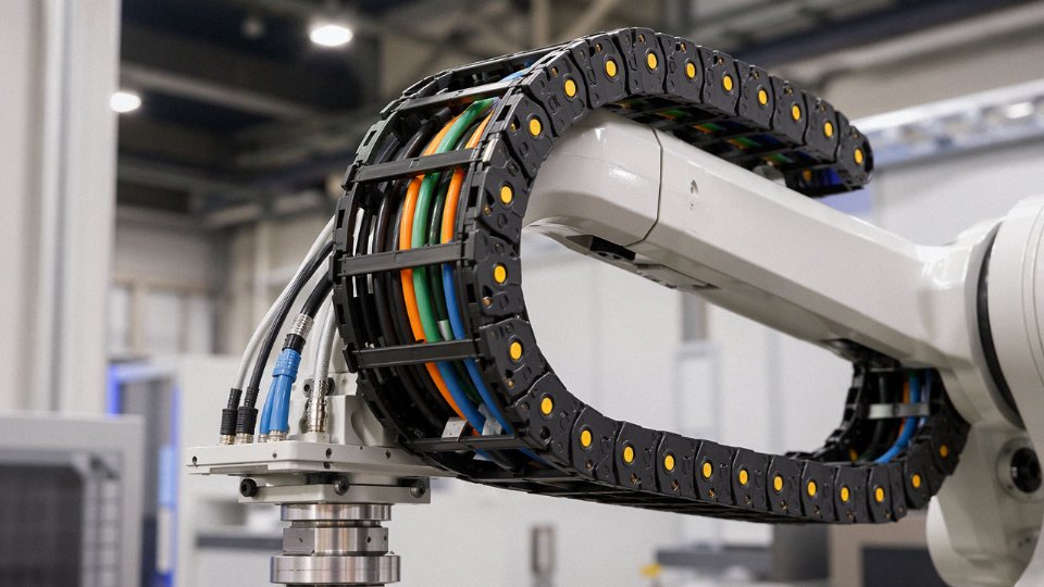
Robot tether cables and servo motor connections are probably the most demanding flex duty you will find in a factory. A six-axis arm running a welding cycle might complete 2–3 million articulations per year, and the cable bundle at each joint sees simultaneous bending, torsion, and lateral displacement. Class 6 fine-wire conductors — typically 189 wires or more in cross-sections from 0.5 mm² up to around 6 mm² for signal and power combined — are the only practical choice here. PUR jacketing resists the hydraulic fluid and weld spatter that are just facts of life in these cells. Specify drag-chain-rated versions for linear tracks and torsion-rated versions for rotary joints; they are not interchangeable, and mixing them up is a common source of premature jacket splitting.
Machine Tools and CNC Equipment
Metalworking environments are quietly brutal on cables. Coolant mist, neat cutting oil, and swarf accumulation will destroy a standard PVC jacket in months. PUR-jacketed Type 3 cables rated against IRM 902 oil per IEC 60811-2-1 hold up considerably better — in practice, two to four times the service life compared to standard PVC in flood-coolant environments, though actual longevity depends heavily on coolant chemistry and whether the cable is clamped or free to drain. Spindle drive cables also need low-capacitance construction to avoid interfering with the drive’s feedback loop at high switching frequencies, so always cross-check the electrical parameters, not just the mechanical flex rating.
Construction and Portable Power Equipment
Rubber-jacketed Type 3 cable — H07RN-F equivalent construction — is standard for portable generators, electric hand tools, and temporary distribution boards on construction sites. The critical spec here is low-temperature flexibility. A cable that stiffens up and cracks at -15°C is a genuine hazard on a winter site; IEC-rated rubber compounds that stay workably flexible down to around -25°C are worth specifying by name in the purchase order, not left to the supplier’s discretion.
Stage, Entertainment, and Event Production
Touring concert and theatre rigs put cables through a punishment that is easy to underestimate: daily coiling and uncoiling by hand, dragging across concrete floors, and getting pinched under equipment cases. Low-smoke zero-halogen (LSZH) or PUR jacketing is mandatory in most enclosed venues and exhibition halls under fire codes, and Class 6 construction means the cable survives the mechanical abuse long enough to matter. Cold-temperature flexibility matters here too — outdoor festivals in spring and autumn regularly drop below 5°C overnight.
Marine, Offshore, and Subsea
Deck equipment and crane control umbilicals on offshore platforms need halogen-free, mud-resistant constructions that carry Type Approval from the relevant classification society — Lloyd’s Register, DNV, Bureau Veritas, or equivalent depending on flag state. ROV tether cables are a specialized subset where neutral buoyancy and seawater resistance compound the flex requirements significantly.
Renewable Energy
Solar tracker systems rotate roughly 180° per day — not extreme torsion, but relentless and continuous over a 25-year asset life. Wind turbine nacelle wiring faces vibration and slow torsional movement as the nacelle yaws. Both applications favor Type 3 construction specifically because the fine-wire conductor handles low-amplitude, long-duration cyclic movement better than a rigid conductor that work-hardens and cracks.
Type 3 flexible cables using Class 5 or Class 6 conductors must pass a minimum of 30,000 standardized flex cycles under IEC 60228, compared to fewer than 5,000 cycles for rigid Class 1 conductors.True
IEC 60228 defines conductor classes and their associated flex-cycle requirements; Class 5 and 6 fine-wire constructions are specifically designed for flexible and highly flexible service duty respectively, with substantially higher cycle thresholds than Class 1 solid or Class 2 stranded rigid conductors.
Medical and Cleanroom Equipment
Silicone-insulated Type 3 cable for patient-connected devices is a different world from industrial automation — biocompatibility certifications, repeated autoclaving or chemical sterilization, and flexibility at body temperature are the governing requirements rather than oil resistance or torsion rating. Class 6 extra-flexible construction in small cross-sections (typically 0.5–2.5 mm²) keeps the cable pliable enough for handpiece leads and pendant cables that clinicians handle constantly throughout a shift. Silicone also tolerates the temperature cycling of steam sterilization without the jacket crazing that eventually shows up in PVC equivalents.
How to Select the Right Type 3 Cable: A Step-by-Step Specification Checklist for Engineers
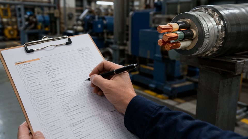
Getting the specification wrong costs more than the cable itself. A re-pull in a drag chain installation, or a premature jacket failure on a robot arm, typically means unplanned downtime measured in shifts, not minutes. Work through the following steps in sequence before issuing any RFQ.
Step 1 — Define the Movement Profile
This is the decision that everything else flows from. There are four distinct categories: static flexible (the cable gets repositioned occasionally during maintenance but doesn’t move in service), dynamic flexible (continuous back-and-forth travel, typically in a cable carrier or drag chain), torsional flexible (rotational movement around the cable’s own axis, common in robot arm wiring), and trailing cable (dragged or pulled across floors in mining, port equipment, or mobile machinery).
Dynamic and torsional applications impose the most demanding requirements on conductor strand count and jacket hardness. For continuous drag-chain duty, you generally need IEC 60228 Class 5 or Class 6 construction — strand counts that can reach 189 or more fine wires per conductor on larger cross-sections — and a jacket Shore A hardness in roughly the 75–85 range, firm enough to resist abrasion from the carrier yet supple enough not to crack under repeated bending. A static flexible cable with a Class 5 conductor will survive torsional service for a while, but it will work-harden and fail early. Don’t assume flexibility grade alone is sufficient; jacket compound selection is equally load-bearing for service life.
Step 2 — Voltage, Current, and Cross-Section
Confirm the system voltage class first: 300/500 V, 450/750 V, or 0.6/1 kV are the most common industrial designations and each corresponds to specific insulation wall thicknesses under IEC 60227 and related standards. Then calculate current-carrying capacity using IEC 60364-5-52 correction factors for grouping and ambient temperature — a cable bundled with five others in a 45 °C enclosure can see a derating of 30–40% compared to its free-air rating, which is enough to bump you one or even two cross-section sizes up from an initial estimate.
Step 3 — Temperature Range
Operating temperature (continuous) and installation temperature (minimum) are two separate numbers and both matter. PVC insulation loses practical flexibility below roughly -5 °C — which sounds fine until you’re commissioning outdoor equipment in January and the cable won’t route cleanly through the carrier. EPR and PUR compounds stay pliable down to around -40 °C; silicone handles down to approximately -60 °C but comes with its own mechanical fragility trade-offs. State both values explicitly in your specification.
Step 4 — Chemical and Environmental Exposure
PVC fails relatively quickly in aromatic hydrocarbons — toluene, xylene-based degreasers — and degrades under prolonged UV exposure without stabilizer additives. PUR resists most cutting fluids and hydraulic oils well and handles ozone better than standard PVC. If you’re in food processing or pharmaceuticals, check whether the jacket compound holds the relevant food-contact or low-migration certification. Get the actual chemical resistance table from the manufacturer, not a marketing claim.
PUR-jacketed Type 3 cables resist most industrial cutting fluids and hydraulic oils better than standard PVC-jacketed equivalents.True
PUR (polyurethane) has significantly higher resistance to aliphatic hydrocarbons, mineral oils, and emulsified cutting fluids compared to general-purpose PVC compounds, a characteristic documented in IEC and manufacturer chemical resistance data.
Step 5 — Shielding and EMC
If the installation falls under the EU Equipment Directive or similar EMC frameworks, an unshielded cable often isn’t an option — confirm this before specifying. Between braid and spiral (served) shields: braid provides better overall coverage and lower transfer impedance, but a spiral shield survives high-cycle flex applications considerably longer because it doesn’t suffer from the work-hardening failure mode at braid crossing points. For drag-chain applications with more than roughly 50,000 cycles expected, spiral shielding is usually the pragmatic choice.
Step 6 — Safety Certifications and Flame Category
Identify the required third-party marks upfront — HAR for Europe, UL/CSA for North America, DNV or BV for marine and offshore — because these affect both the manufacturing process and lead times. Flame and smoke category isn’t interchangeable: IEC 60332-1 covers single-cable flame propagation, IEC 60332-3 covers bunched cables in tray installations, IEC 61034 covers smoke density, and IEC 60754 covers halogen emission. In public infrastructure, rolling stock, and offshore platforms you typically need all four. Specify each one explicitly; “flame retardant” alone is ambiguous.
Step 7 — Mechanical Protection and Bend Radius Compatibility
Before finalizing the cable selection, measure the actual bend radius of the drag chain or cable carrier already installed on the machine. A standard catalog chain from a major European manufacturer typically runs minimum bend radii between 50 mm and 300 mm depending on the chain series — and the selected cable’s allowable dynamic bend radius must be equal to or less than that figure. If it isn’t, you either need a more flexible cable variant or a different carrier. This check gets skipped constantly in practice and it is one of the more avoidable causes of early cable failure.
Type 3 Cable Testing Methods and Quality Verification: What Factories Should Prove Before You Buy
Every procurement manager who has dealt with a field failure caused by substandard flexible cable knows the real cost is never just the cable itself — it’s the unplanned downtime, the root-cause investigation, and the credibility problem with the end customer. Getting the right test documentation before the order ships is the only practical defense.
Routine Tests on Every Production Reel
These are the baseline. If a supplier can’t produce these for each reel, stop the conversation.
Conductor DC resistance per IEC 60228 confirms that the actual conductor cross-section matches what’s printed on the drum label. Resistance values depend on temperature, so check that the test report references 20 °C. A reading more than roughly 5–8% above the standard limit usually means the conductor is undersized — either fewer wires than specified or wires drawn slightly oversize during fine-wire production. Either way, you have a heating problem waiting to happen.
Spark testing (high-voltage AC or DC, typically 6–8 kV depending on insulation wall thickness) is run inline at production speed on 100% of the cable. Any pinhole, thin spot, or contaminant in the insulation wall triggers a spark event and flags that meter length for rejection. A factory running a genuine 100% spark-test line will have continuous pass/fail logs tied to reel serial numbers. If the supplier offers only a batch sample certificate, that’s a process gap worth probing.
Insulation resistance measurement, usually expressed as MΩ·km, validates bulk insulation quality after extrusion. Values well below the IEC minimums — which depend on insulation material and conductor size but commonly fall in the range of hundreds to several thousand MΩ·km — indicate absorbed moisture, degraded compound, or contamination during extrusion. A marginally low result that passes on the day of shipment can fail within weeks once the cable is in a humid or thermally cycled environment.
Type Tests and Design Qualification
Type tests are not run on every reel; they qualify the design. But they must exist, and they must match your actual product, not a related variant.
The flex endurance test is the one that matters most for Type 3. Conductor class (IEC 60228 Class 5 or Class 6) and wire diameter directly affect cycle count — a Class 6 construction using wire finer than 0.1 mm will outlast a coarser Class 5 conductor by a significant margin in continuous flex applications, sometimes by a factor of three or more depending on bend radius and the mechanics of the installation. Demand the actual cycle count achieved, not just a “pass” statement.
Tensile strength and elongation at break per IEC 60811 confirm that the insulation and jacket compounds haven’t been over-extended or under-cured during processing. Cold-bend testing at the cable’s minimum rated temperature (often −30 °C or −40 °C for general industrial grades) checks whether the jacket or insulation cracks when handled in cold storage or outdoor winter installations — a failure mode that often doesn’t show up visually until the cable is energized.
For oil-resistant jackets, the oil immersion test per IEC 60811-2-1 is non-negotiable on machine tool and press-floor applications. Compound that hasn’t been properly formulated will swell, soften, and lose tensile properties after immersion, typically tested at elevated temperature over 24–168 hours depending on the sub-test.
Fire Performance: Match the Test to the Application
This is an area where under-specification is genuinely dangerous and over-specification just wastes money.
IEC 60332-1 (single vertical flame, single cable) is the minimum for most industrial installations. IEC 60332-3 tests bunched cables and matters the moment you’re running cables in trays or conduit — Category A is the most demanding, suited for large cable installations in buildings or tunnels; Category C covers the majority of industrial panel and machinery builds. IEC 61034-2 (smoke density) becomes critical in enclosed spaces where evacuation is a concern — metro systems, tunnels, offshore platforms. IEC 60754-1 and -2 measure halogen acid gas emission and corrosivity, which is why LSZH (low-smoke zero-halogen) cables carry these certificates: in a fire, halogen gases corrode electronics and are toxic in confined spaces. If your project spec says LSZH, the cable needs both 60754 tests, not just the smoke density test.
Third-Party Certification vs. Self-Declaration
A manufacturer’s own test report is only as trustworthy as the manufacturer’s lab and their incentive to be honest. A certificate issued by a notified body — VDE, KEMA, DEKRA, BASEC, UL, or similar — means an independent organization tested production samples and audits the factory periodically for compliance. The difference matters most when the cable is going into a regulated application (medical, offshore, rail) or crossing into a market where customs or the end customer will scrutinize documentation.
Third-party certified flexible cables (e.g., VDE or KEMA approved) provide stronger supply chain assurance than manufacturer self-declaration alone.True
Notified bodies conduct independent sample testing and periodic factory audits, whereas a manufacturer's own test report reflects internal testing with no external verification of equipment calibration, sample selection, or result integrity.
Reading a Certificate Correctly
Most procurement teams look at the logo and the pass/fail line. That’s not enough. Check: the test standard version (IEC 60811:2012 and older editions have different test protocols — a certificate against a superseded edition may not satisfy a current project spec); the sample description, which should explicitly state conductor class, cross-section, number of cores, insulation and jacket material, and construction details; the certificate validity date and scope (some certificates cover a cable family defined broadly, which may or may not include the specific cross-section you’re ordering). When in doubt, ask the supplier to confirm in writing that the certificate scope covers the exact part number on your purchase order.
Factory Audit Indicators for Flexible Cable Quality
The equipment a factory runs tells you whether their quality claims are physically achievable. Fine-wire drawing for IEC 60228 Class 6 conductors requires wire drawn to below 0.1 mm diameter, which demands precision drawing dies, tension control, and annealing equipment that a rigid-cable facility simply doesn’t have. Computer-controlled stranding machines with real-time tension monitoring ensure consistent lay length and prevent the uneven wire distribution that causes premature fatigue in flex cycles. Environmental test chambers capable of −40 °C cold-bend and heat-aging at 100–136 °C support genuine in-house type testing rather than outsourcing to a lab the supplier rarely uses. Jinda’s five production bases covering 470,000 m² are structured to keep fine-wire drawing, stranding, extrusion, spark testing, and environmental testing within the same manufacturing system — which matters for traceability when a customer requests full batch records on a critical project.
The uncomfortable reality: a supplier who pushes back on providing reel-level test reports, whose certificates reference vague sample descriptions, or who can’t show you a spark-test log tied to your specific reel serial number is asking you to absorb quality risk that they should be carrying. That’s worth remembering before you approve the shipment.
Frequently Asked Questions About Type 3 Cable
Is Type 3 cable the same as Class 5 or Class 6 in IEC 60228?
Not exactly, and the distinction matters when writing specifications. “Type 3” is a flexibility designation that appears in certain national and product standards — it tells you the cable is intended for flexible or portable use. IEC 60228 is a different document entirely: it defines conductor construction classes, where Class 5 sets the wire count and maximum strand diameter needed to achieve flexible-service performance, and Class 6 pushes further into fine-wire territory for extra-flexible duty.
In practice, most Type 3 cables are built on Class 5 conductors. Type 3H or “highly flexible” variants — the kind you’d find on a welding set lead or a portable drill press — use Class 6. The two standards are complementary, not interchangeable labels for the same thing. A cable can satisfy IEC 60228 Class 5 without being designated Type 3 in any product standard, so always verify both the conductor class and the product standard on the test report, not just one of them.
Can Type 3 cable be used in fixed conduit installations?
Yes, without any technical objection. The flexible conductor construction does nothing harmful in a static installation — it simply sits there. What you are paying for is flex capability you will never use. Depending on cross-section and jacket material, Type 3 will run roughly 15–40% more expensive than an equivalent rigid Type 1 cable, depending on copper pricing, strand count, and order volume. If budget is tight and the cable genuinely never moves after installation, Type 1 or Type 2 is the rational choice. That said, in mixed plants where maintenance teams pull and re-route cables during shutdowns, having Type 3 throughout simplifies stocking and reduces the risk of someone grabbing the wrong reel.
What is the maximum voltage rating available for Type 3 flexible cable?
Standard product ranges cover 300/500 V for light-duty portable equipment and 450/750 V for industrial and heavy-duty applications. Those two ratings cover the vast majority of plant-floor use. Beyond that, medium-voltage flexible cables — typically 6/10 kV, sometimes 8.7/15 kV — are manufactured with Class 5 stranded conductors specifically for mining trailing cables, offshore umbilicals, and mobile substations. Construction at those voltage levels adds screening, additional insulation thickness, and usually an armoring or reinforcing layer, so lead times and minimum order quantities are considerably longer. Don’t assume a standard catalog item exists; MV flexible cable is almost always made to order.
How do I identify a Type 3 cable by its designation code?
The harmonized European system is the most systematic. Take H07RN-F 3G2.5: H = harmonized standard, 07 = 700 V (450/750 V system), R = rubber insulation, N = natural rubber jacket, F = flexible (Class 5 conductor), 3G = three conductors including a green/yellow earth, 2.5 = 2.5 mm² cross-section. Each position in the code carries specific meaning once you know the key.
Equivalent designations in other systems include SOOW under UL/NEC (North America), NGFLGÖ under VDE (Germany), and YZ or YC under Chinese GB standards. The underlying construction is often similar; the naming convention just reflects which standards body wrote the product specification. When importing cable across markets, map the designation codes carefully — a procurement manager assuming SOOW and H07RN-F are interchangeable has occasionally discovered voltage-rating or jacket-compound differences after the cable is already on site.
What is the difference between drag-chain cable and standard Type 3 flexible cable?
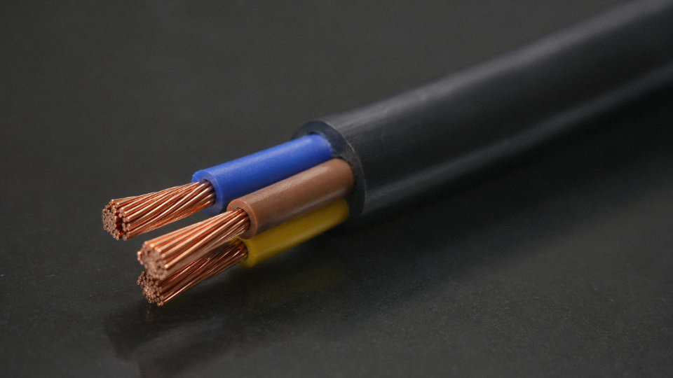
This is probably the most common misspecification I see. Type 3 is rated for repeated flexing — the IEC 60228 Class 5 conductor test standard requires a minimum of 30,000 flex cycles, which sounds like a lot until you put it on a machine tool axis cycling 80 times per hour. Drag-chain (cable carrier) cables are a specialized sub-category engineered for continuous, unidirectional back-and-forth bending; they are tested to millions of cycles, use finer wire stranding than standard Class 5 or 6, and typically carry a harder polyurethane jacket that resists both abrasion against neighboring cables inside the carrier and the compressive loads the carrier trough imposes. The jacket hardness that makes a drag-chain cable durable in a carrier would make a standard Type 3 cable feel stiff and unpleasant to handle in a handheld tool application. Specify drag-chain cable for drag-chain applications; don’t assume any flexible cable qualifies.
How should Type 3 cable be stored to avoid pre-installation damage?
Store on the original reel, upright, in a dry indoor space at roughly 5–35°C. This sounds obvious, but outdoor laydown yards in summer can hit 50°C at ground level, and PVC jackets left coiled tight under that heat will take a permanent set. Never coil tighter than the cable’s minimum bend radius — for a 2.5 mm² H07RN-F that’s typically around 40–50 mm, depending on overall diameter. Don’t stack heavy items on reels; flattening the cross-section stresses conductors unevenly and can cause pre-installation insulation cracking. Rubber-jacketed cables have one specific storage sensitivity that catches people off guard: ozone. Electric motors and older fluorescent ballasts both emit ozone, and rubber jackets can micro-crack with prolonged exposure even before the cable has been touched. Keep rubber cable away from those sources in storage.
Does Jinda supply custom Type 3 cable constructions for non-standard specifications?
Yes. With R&D, production, and technical support under one roof across five manufacturing bases in China, Jinda can accommodate non-standard conductor cross-sections, unusual core counts, specialty jacket compounds (silicone, TPE, low-smoke halogen-free), and customer-specific color coding or sequential meter marking. Custom constructions go through full test certification at accredited third-party laboratories.
Jinda's Type 3 flexible cables are produced across five integrated manufacturing bases in China with full in-house R&D, testing, and after-sales support.True
This reflects verified organizational information about Shandong Jinda Special Cable Group Co., Ltd. as provided in the project brief.
Lead times for custom work vary considerably — a minor jacket color change on a running product might add two to three weeks, while a new conductor-insulation-jacket combination requiring new tooling and a full type-test campaign realistically takes three to five months. Get that timeline discussion started early if you’re working toward a project commissioning date.