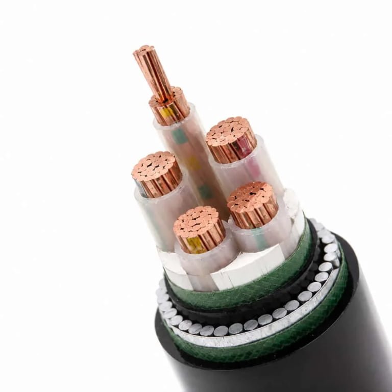
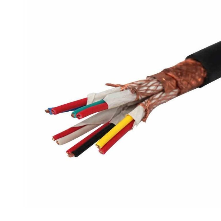
Get the burial depth wrong on a low voltage cable run and you will not find out immediately — you will find out at the worst possible moment. A cable laid 300 mm too shallow under a yard where forklifts eventually start tracking a new path, or under ground that freezes harder than the original site survey suggested, will fail in ways that are maddeningly difficult to fault-find: intermittent insulation breakdown, ground fault trips that clear themselves, neutral degradation that shows up as flickering on a panel three buildings away. Excavating to locate the fault costs more than the original installation would have cost done properly. That gap between “we followed a rough rule of thumb” and “we followed the applicable standard for this specific loading condition” is where most buried cable failures actually live.
For most low voltage cable installations rated 600 V to 1000 V, the minimum burial depth runs from 600 mm to 1000 mm depending on jurisdiction, soil conditions, and whether vehicular traffic crosses the route. IEC 60364-5-52 sets 600 mm as a common residential baseline; NEC Article 300.5 requires up to 900 mm under roadways carrying vehicle traffic. Adding mechanical protection — conduit or concrete encasement — can legally reduce those figures by 150–300 mm under the relevant standard.
What most site guides skip entirely is the conditional logic underneath those numbers. The 600 mm figure is not a universal safe answer — it is a floor that applies under a specific set of assumptions, and several ordinary site conditions will push the requirement higher before you even consult the local authority. Understanding which variables actually move the needle, and by how much, is the difference between a cable trench you dig once and one you dig twice.
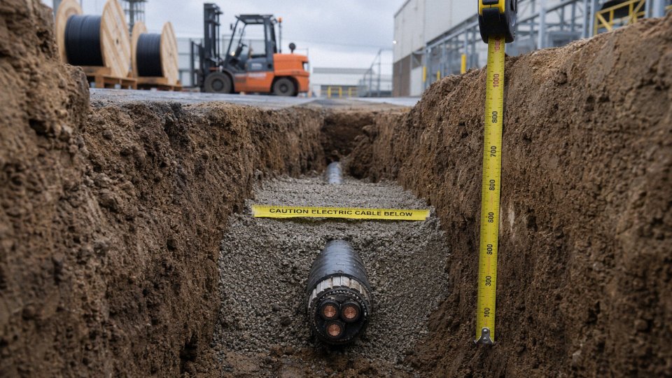
International Standards Compared: IEC, NEC, BS 7671, and AS/NZS Minimum Depth Requirements
Getting burial depth right starts with knowing which rulebook actually governs your project — and that answer is less obvious than it sounds. Four frameworks dominate most of the world’s low voltage underground work, and they don’t fully agree with each other.
IEC 60364-5-52: The Global Baseline
IEC 60364-5-52 sets a 600 mm minimum cover for cables rated up to 1000 V installed directly in general ground. That figure is widely cited as the international reference point, but in practice it functions more as a floor than a finished answer. National annexes routinely push the requirement upward — Germany, the Netherlands, and several Gulf states all adopt the IEC family but apply local deviations that can reach 700–800 mm in standard ground. If you’re supplying cable for a project that says “designed to IEC,” ask immediately which national annex applies before the trench dimensions are locked.
NEC Article 300.5: North American Complexity by Wiring Method
The NEC takes a different approach. Rather than a single depth figure, Article 300.5 ties minimum cover to the wiring method, voltage level, and location. The key numbers:
| Wiring Method | Residential 120/240 V | Commercial / 600 V Class | Under Concrete Slab |
|---|---|---|---|
| Direct burial cable | 600 mm (24 in) | 600 mm (24 in) | 150 mm (6 in) |
| Rigid metal conduit (RMC) | 150 mm (6 in) | 150 mm (6 in) | 150 mm (6 in) |
| Intermediate metal conduit | 150 mm (6 in) | 150 mm (6 in) | 150 mm (6 in) |
| PVC conduit (Schedule 80) | 450 mm (18 in) | 600 mm (24 in) | 150 mm (6 in) |
| Under a public road or driveway | 600 mm minimum regardless of method | 600 mm minimum | — |
The distinction between residential 120/240 V branch circuits and commercial 480 V feeders matters particularly for Schedule 80 PVC: the residential allowance of 450 mm disappears once you cross into the commercial voltage tier. Inspectors catch this regularly on mixed-use development sites where the electrical design shifts from residential panels to a commercial service entrance partway through the same trench run.
NEC Article 300.5 permits direct burial cable at 150 mm depth when installed under a concrete slab at least 50 mm thick.True
NEC Table 300.5 explicitly lists 6 inches (approximately 150 mm) as the minimum cover for direct burial cables installed beneath a concrete slab of at least 2 inches (50 mm), regardless of voltage class up to 600 V.
BS 7671 / IET Wiring Regulations 18th Edition: Depth Plus the Tape Requirement
BS 7671 (18th Edition) is the governing standard across the UK and much of the Commonwealth. Minimum depths are 500 mm under footpaths, 600 mm in gardens and cultivated ground, and 900 mm beneath roads carrying vehicle traffic. Those numbers are fairly consistent with IEC, but BS 7671 adds an operational requirement the other standards don’t mandate: a marker tape — typically yellow, reading “Caution: Buried Cable Below” — must be laid roughly 100 mm above the cable. In practice that tape has probably prevented as many third-party dig-ins as the depth itself. Skipping it is a compliance failure and, more importantly, a genuine hazard when a landscaper with a mini-excavator shows up two years later.
AS/NZS 3000 and AS/NZS 3008: Australia and New Zealand
The AS/NZS framework specifies 500 mm in lawns and garden beds, 600 mm under driveways and private vehicle areas, and 750 mm under public roads. Those numbers look slightly shallower than some other regimes at the road level, but the practical ceiling is higher than the standard suggests — state-level Distribution Network Service Provider (DNSP) rules in Queensland, Victoria, and New South Wales frequently impose their own requirements that exceed AS/NZS 3000 minimums by 100–200 mm. For any grid-connection work or street-crossing in Australia, the local DNSP specification is the one that actually controls. The AS/NZS standard is the fallback, not the final word.
The Multi-Standard Trap
| Standard | Region | General Ground | Under Road | Conduit Reduction | Key Reference |
|---|---|---|---|---|---|
| IEC 60364-5-52 | Global (with national annexes) | 600 mm | 900 mm (typical annex) | 150–300 mm | Clause 522.8.10 |
| NEC Article 300.5 | USA and territories | 600 mm (direct burial) | 600 mm | Down to 150 mm (RMC) | Table 300.5 |
| BS 7671 18th Ed. | UK, Commonwealth | 600 mm (garden) | 900 mm | ~150 mm with protection | Regulation 522.8.10 |
| AS/NZS 3000 | Australia, New Zealand | 500–600 mm | 750 mm | 150 mm typical | Clause 3.9 |
The common trap on international or investor-funded projects: cables crossing a border, or a project where the owner specifies NEC compliance on a site physically located in an IEC jurisdiction. Both sets of rules then technically apply, and they don’t always produce the same trench depth. This conflict must be resolved in writing — ideally in the project specification — before trenching begins, not discovered during an inspection. A 150 mm difference in specified depth across a kilometer-long cable route is a non-trivial rework cost if the wrong standard was followed.
How Surface Loading and Traffic Classification Change the Required Depth
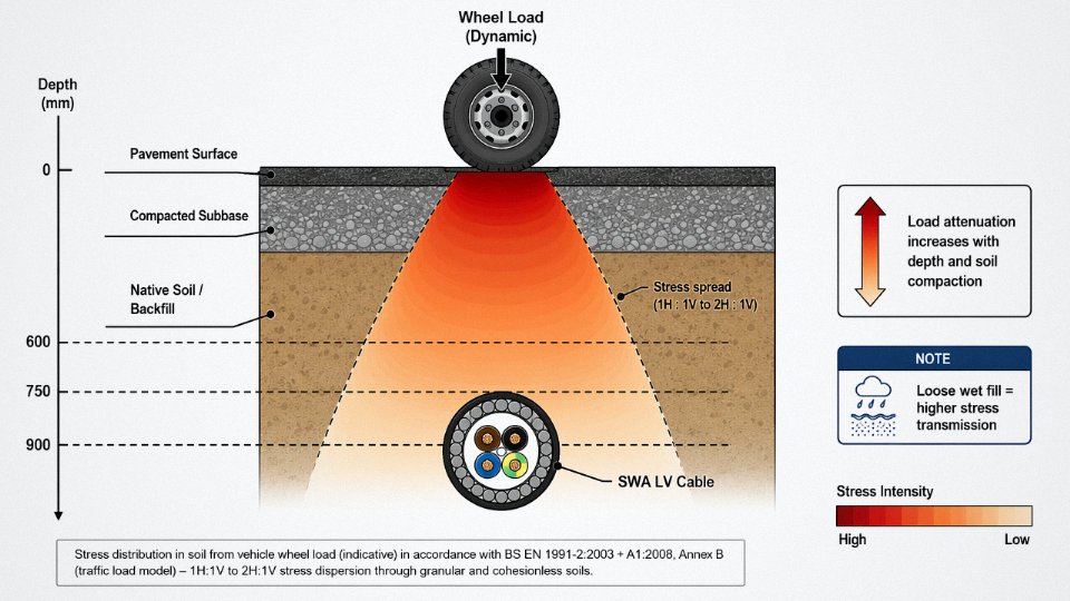
The ground above a buried cable is not passive. Every vehicle that crosses it sends a pressure wave downward through the soil column, and that wave doesn’t disappear — it attenuates with depth, spreading across a wider area as it goes. The question engineers need to answer before setting trench depth is simple but consequential: at the burial plane, does the residual soil stress exceed the cable’s rated crush resistance? Get that wrong and you’re not looking at immediate failure. You’re looking at progressive armor deformation, insulation creep, and an intermittent fault that shows up 18 months later during a production peak.
The Physics Behind the Depth Requirement
Dynamic wheel loads are worse than static ones — typically by a factor of 1.3 to 1.5 for highway vehicles, higher for plant equipment with hard rubber or steel wheels. Soil transmits these loads as a cone of stress that widens roughly at a 1:1 to 2:1 ratio depending on compaction and moisture content. Loose, wet backfill transmits load more efficiently (and more dangerously) than well-compacted granular fill. That’s worth remembering when the groundworks crew is rushing to close a trench before rain.
Four Practical Surface Loading Zones
In practice, site engineers work with four surface categories, each carrying a depth increment above the residential baseline (typically 600 mm under IEC 60364-5-52 or NEC Article 300.5 for non-traffic zones):
| Surface Zone | Typical Traffic | Depth Over Baseline | Notes |
|---|---|---|---|
| Pedestrian only | Foot traffic, cyclists | +0 mm (baseline applies) | Verify no future vehicle access |
| Light vehicle | Passenger cars, light vans | +150–200 mm | Common in residential driveways |
| Medium vehicle | Delivery trucks, ≤3.5 t axle | +200–300 mm | Industrial estates, loading areas |
| Heavy vehicle / HGV | Articulated trucks, plant, rail | +300–500 mm, plus duct | Often 900–1100 mm minimum cover |
These increments depend on soil class, cable OD, and whether mechanical protection is added. They are not universally codified — some jurisdictions specify them directly, others leave it to engineering judgment backed by BS EN 1991-2 (traffic loading) or AASHTO for North American projects.
Road Resurfacing: The Retroactive Hazard
Here’s a situation that catches people out regularly. A cable buried to 750 mm cover in 1998 may now sit at only 580 mm cover because the road surface has been built up through successive resurfacing layers — 40 mm here, 30 mm there. The cable hasn’t moved. The grade level has. As-built records showing depth to cable centerline from the original surface datum are essential, and frankly, most facilities don’t keep them well enough. If you’re taking over an existing site, probe before you assume.
Road resurfacing can reduce the effective cover depth of a buried cable without any excavation or cable movement occurring.True
Each asphalt overlay raises the finished grade level, reducing the vertical distance between the cable and the new surface. A cable originally installed at 750 mm cover can end up with 550 mm or less after two or three resurfacing cycles over 20–30 years.
Armor Selection as a Depth Management Tool
Steel wire armored (SWA) cable and steel tape armored (STA) cable both provide crush resistance that some standards recognize as a partial substitute for burial depth. IEC and BS 7671 allow reduced minimum cover — typically 150–300 mm less than unarmored equivalents — when armored cable is direct-buried. A worked example: unarmored 1 kV cable under a light vehicle zone might need 900 mm cover; the same route using SWA cable could be acceptable at 600–700 mm under the same standard, depending on the authority having jurisdiction. SWA is generally preferred for cables above 50 mm² where longitudinal mechanical stress during installation is also a concern; STA suits smaller conductors in stable soil where the primary risk is radial crushing.
In my experience, SWA adds meaningful protection against incidental excavation damage too — a JCB bucket that would sever an unarmored cable will often slide off SWA, giving the operator a chance to stop. Not guaranteed, but it matters.
Special Cases That Need Their Own Rules
Rail crossings are categorically different. Network Rail (UK) specifies 1000–1200 mm minimum cover for LV cables crossing under tracks, with mandatory duct encasement and marker tape. UIC 778-3 sets similar requirements for international rail infrastructure. The dynamic loading from a loaded freight bogie is a different order of magnitude from a road vehicle, and the vibration is cyclical, which accelerates mechanical fatigue.
Airport aprons present a related problem: aircraft ground loads are extremely high, concentrated over small gear footprints, and the soil is typically heavily compacted to a controlled bearing capacity — which actually helps with load distribution. Apron cable installations usually require concrete duct encasement regardless of depth.
Frost-heave-prone soils add a different constraint entirely. In climates where the frost line reaches 600–900 mm (northern Canada, Scandinavia, parts of northern China and Russia), burial depth must place the cable below the frost line, not just meet the traffic loading requirement. These two requirements must be evaluated together, and the deeper of the two governs. A cable at 800 mm in Manitoba might be fine for traffic loading but still within the frost zone in a severe winter.
Loading Zone Decision Matrix
| Surface Zone | Min Cover (Unarmored) | Min Cover (SWA/STA) | Recommended Armor | Additional Measures |
|---|---|---|---|---|
| Pedestrian | 600 mm | 450–500 mm | Optional | Warning tape |
| Light vehicle | 800–900 mm | 600–700 mm | STA or SWA | Warning tape + marker posts |
| Medium vehicle | 900–1000 mm | 700–800 mm | SWA | Concrete slab or duct |
| HGV / plant | 1000–1100 mm | 900–1000 mm | SWA mandatory | Duct encasement + concrete |
| Rail crossing | 1000–1200 mm | 1000–1200 mm | SWA + duct | Concrete encasement required |
Depths shown are indicative ranges; verify against the governing national standard and the specific soil investigation for the site. Soil bearing capacity and backfill specification both shift these numbers.
Soil Type, Thermal Resistivity, and the Hidden Depth-Versus-Ampacity Trade-off
Burial depth conversations almost always focus on mechanical protection and regulatory minimums. The electrical side of the equation — what depth actually does to a cable’s continuous current rating — gets far less attention, and that gap causes real problems on commissioning day.
Why Soil Thermal Resistivity Matters More Than Most Site Engineers Expect
Every current-carrying cable is a heat source. The soil around it is the heat sink. How efficiently that heat gets away from the cable depends almost entirely on the soil’s thermal resistivity, measured in K·m/W. Dry sand typically sits around 2.0–2.5 K·m/W. Moist loam comes in around 0.9–1.2 K·m/W. Wet clay can drop to 0.7–0.9 K·m/W. Those differences are not academic — a cable rated for, say, 250 A in moist loam may need to be derated to somewhere in the 195–220 A range if it ends up in the same trench geometry but surrounded by dry sand. The thermal path is longer and more resistive, so the conductor runs hotter at the same load.
Depth compounds this. IEC 60287 models the soil above the cable as a thermal resistance that the cable heat must conduct through to reach ambient. Bury a cable at 700 mm in dry sandy soil, then move it to 1200 mm in the same soil without changing anything else, and the continuous current rating typically drops by somewhere between 8 and 15%, depending on conductor cross-section, cable construction, and actual soil moisture content at that depth. The deeper zone in many climates is drier and more thermally resistive than the surface layer. You gained mechanical protection; you quietly lost ampacity.
Controlled Thermal Backfill: The Engineered Fix
The practical solution on medium-to-large installations is controlled thermal backfill, usually abbreviated CTB. It’s a sand-cement-flyash mixture — proportions vary, but the target is a placed thermal resistivity of roughly 0.7–1.2 K·m/W once cured, combined with adequate compressive strength to prevent settlement. CTB gets placed in the immediate cable zone, typically 150–300 mm around the cable or duct, and it breaks the dependence between burial depth and ampacity loss. You can go to 1200 mm for traffic loading compliance without accepting the thermal penalty of native sandy soil at that depth. The material cost is real but usually modest relative to the cable cost, and on a high-load feeder circuit it often saves a conductor size upgrade.
Rock, Coral, and Hard Compacted Soils
In some sites — basalt underlays in volcanic regions, coral limestone in Pacific island projects, heavily compacted laterite in parts of Africa and Southeast Asia — trenching to 900 mm or 1000 mm is either prohibitively expensive or genuinely impractical. Most standards permit reduced cover depths when cables are routed through rigid conduit or concrete encasement, typically allowing 150–300 mm of reduction. Beyond the compliance benefit, a cable-in-duct system allows future replacement by pulling new cable without re-excavation. That replaceability argument tends to win the cost-benefit analysis quickly on any circuit that runs under hardscape.
The Moisture Migration Problem in Sandy Soils
A subtler failure mode appears in dry or desert climates where a continuously loaded cable in sandy soil at 600 mm depth generates enough sustained heat to drive residual moisture outward, progressively drying the surrounding soil and raising its thermal resistivity over months or years. This isn’t a theoretical concern — it’s a well-documented mechanism in IEC 60287-1-1. The safe response is either conservative derating from the outset, a thermal engineer’s site-specific assessment, or CTB to stabilize conditions.
Matching Cable Construction to Soil Conditions
Depth and soil aggressiveness should also drive cable construction choices. XLPE insulation outperforms PVC above roughly 70°C continuous conductor temperature and handles thermal cycling better over decades in deep installations. In soils with high sulfate content, acidic pH, or wet-dry cycling, an outer jacket of medium-density polyethylene or a corrugated steel armor with PE oversheath significantly extends service life compared to plain PVC oversheath, which can become brittle and crack over 15–25 years in aggressive ground conditions. Jinda’s armored XLPE constructions — the double steel wire armored and corrugated aluminum sheath variants — are specified specifically for situations where both depth and soil chemistry create long-term degradation risk.
Increasing burial depth always improves cable ampacity by placing the cable in cooler, more stable ground.False
Deeper burial increases the length of the thermal conduction path to the surface and, in dry sandy soils, places the cable in drier, more thermally resistive ground. This typically reduces continuous current rating by 8–15% compared to shallower burial in the same soil, unless controlled thermal backfill is used to manage the thermal environment around the cable.
Mechanical Protection Methods and How Each One Affects Your Trench Depth
The choice of protection method isn’t just a materials question — it directly sets your legal minimum depth, your trench excavation cost, and your long-term liability if something goes wrong. Get it backwards and you’re either over-excavating (wasted labor, disrupted services) or under-protecting (potential cable strike, regulatory non-compliance, insurance disputes).
Direct Burial Without Additional Protection
This is acceptable only when you’re using an armored cable — SWA (steel wire armored) or XLPE/SWA/PVC to IEC 60502-1, or an equivalent armored construction — in stable, undisturbed ground away from vehicle traffic. The armor resists incidental dig-in damage from hand tools, but it is not a substitute for depth in trafficked ground. Typical minimum depth ranges from 600 mm in residential pedestrian-only zones to 900 mm under lightly loaded private roadways, depending on jurisdiction and soil class. Unarmored cable direct-buried without conduit doesn’t meet most utility or municipal specifications full stop, regardless of depth.
Plastic Conduit and HDPE Duct
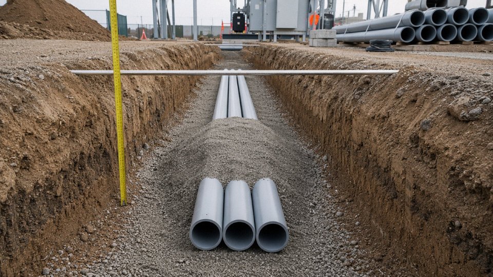
Encasing a cable in a rigid or semi-rigid duct — HDPE, uPVC, or corrugated HDPE (“twinwall”) — isolates it from point loads by distributing stress across the conduit wall and surrounding bedding. This is where you get a genuine depth credit. Under NEC Article 300.5, rigid metal or nonmetallic conduit in residential applications can reduce the cover requirement to roughly 450 mm. Some IEC national annexes permit 500 mm to the top of the duct under similar conditions. The conduit-fill rule for LV feeders is one cable per duct — not because of electrical code per se, but because pulling two feeders through a single duct creates unmanageable friction over any appreciable run length and makes future replacement nearly impossible without cutting. Spare ducts (capped and mandrel-tested) cost almost nothing incremental and have saved more than a few projects from expensive re-excavation.
Concrete Encasement
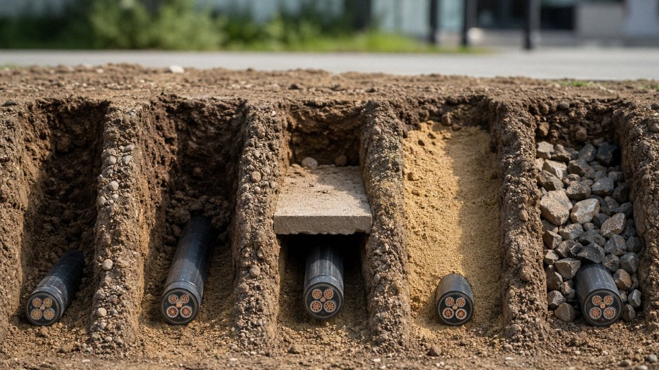
A concrete surround — typically 75–100 mm around the conduit or cable — substantially increases the structural load capacity of the installation and is the standard requirement under public roads, footpaths with vehicle crossings, and any surface subject to unpredictable heavy loading. Minimum mix specification is C20 (20 MPa compressive strength); weaker mixes crack under thermal cycling and lose their protective function faster than you’d expect. The concrete itself doesn’t reduce depth arbitrarily — you still need 600–700 mm from finished surface to the top of the concrete envelope under most road-crossing specs, which means the cable sits at roughly 700–800 mm depending on conduit diameter. Yellow polyethylene marker tape must be laid 300 mm above the top of the concrete, in the backfill, as a mandatory secondary warning layer. Skipping the tape because “the concrete is obvious” is a common mistake that creates real problems during future utility work.
A 75–100 mm C20 concrete surround meets the structural load requirement for cable installations under public roads in most IEC-aligned national standards.True
IEC 60364-5-52 and associated national annexes specify concrete encasement as the accepted method for installations under trafficked surfaces; C20 is the widely referenced minimum compressive strength in civil works specifications associated with these installations.
Cable Protection Tiles and Cover Slabs
Clay or concrete tiles placed 150–250 mm above the cable serve as a physical strike warning during future excavation. They do not earn you a depth reduction — the cable still has to be at the required minimum depth beneath them. Utility companies, particularly DNOs in the UK and network operators following AS/NZS 3000 in Australia, mandate them regardless of armoring. In practice, the tile layer is the thing that stops a careless excavator bucket from severing a feeder before the operator even realizes there’s a cable there. Cheap insurance.
Warning Tape and Electronic Marker Systems
Bright yellow polyethylene marker tape (“CAUTION — BURIED ELECTRIC CABLE”) installed at approximately 300 mm depth acts as the first visual alert during hand-dig verification. This is separate from the tape above concrete described earlier. Electronic marker balls — passive RFID devices placed at joints, changes of direction, and service connections — allow GPS-compatible detection wands to locate the cable without excavation. Their real value is in the as-built record: a GPS survey of the installed route, logged against the electronic markers, is the document that prevents third-party dig-ins five or fifteen years later when nobody on site remembers where the cable runs. Many contractors treat as-built records as a paperwork formality. They’re not. They’re the difference between a routine utility query and a four-day outage plus a legal dispute.
Bundling, Trefoil Arrangement, and the Depth-Derating Interaction
When multiple LV cables share a single trench, mutual heating becomes the governing constraint. Three single-core 240 mm² XLPE cables in trefoil touching formation, direct buried at 700 mm in average soil (thermal resistivity roughly 1.0–1.5 K·m/W), typically require a grouping derating factor of around 0.79–0.82 compared to a single cable in isolation — the exact figure depends on soil thermal resistivity, burial depth, and ambient ground temperature, all of which shift seasonally. Increasing the trench depth to 900 mm improves heat dissipation slightly, but the more effective intervention is horizontal separation: 250 mm between cable centers reduces mutual heating substantially and usually recovers most of the derated ampacity without deepening the trench. If you must run the cables in touching trefoil due to trench width constraints, apply the full IEC 60364-5-52 Table B.52.21 derating and upsize the cable cross-section accordingly at the design stage — not as a site fix after the cable is already on the drum.
Step-by-Step Trench Design and Cable Laying Procedure for Compliant LV Installations
Getting the standards right on paper means nothing if the trench itself is wrong. Every phase below builds directly on the depth and protection decisions covered in earlier sections — skip a step and you’ll likely be digging again.
Step 1 — Pre-Installation Survey
Before a single bucket of soil moves, run a CAT (Cable Avoidance Tool) and signal generator (Genny) sweep across the entire route. In practice, passive CAT scanning alone misses dead cables and plastic water mains, so always use the Genny to induce a signal on metallic services. Mark every detected utility with spray paint and flag pins, then cross-reference with the utility records you should have already requested — they rarely match perfectly, which is why both are necessary.
Soil classification matters here, not just for trench wall stability but because it feeds directly into the thermal resistivity assumptions you made at the design stage. A quick hand-texturing test or a lab sample from the route centreline will tell you whether you’re in sandy loam, heavy clay, or something worse. If the route profile has significant gradients, a simple level survey prevents the annoying situation where your trench hits minimum depth at one end and is 400 mm too deep at the other. Permits and traffic management approvals should be in hand before excavation begins — not chased in parallel. Regulatory inspectors have very little sympathy for “we started and then applied.”
Step 2 — Trench Excavation
Trench width should be cable OD plus at least 150 mm either side. For a single 95 mm² multicore that’s roughly 400 mm wide minimum; for a multi-cable run with mandatory separation, add the required inter-cable spacing on top. Trench walls in loose granular soils need shoring — a trench box or hydraulic shores depending on depth and ground conditions. Don’t rely on the “it’ll probably be fine for a day” logic; trench collapses are fast and the consequences are severe.
High water-table sites need continuous dewatering throughout excavation and laying. A small submersible pump and a temporary sump at the lowest point of the trench is the standard approach. Laying cable into standing water is a quality and safety failure regardless of whether the cable itself is rated for it.
Step 3 — Bedding Layer
Place 75–100 mm of fine sand or selected fine granular fill at the trench bottom before any cable goes in. The material must be free of stones larger than roughly 20 mm — in practice, screened sharp sand works well; unscreened site-won material almost never does. Compact lightly to close voids. Point loading from an undetected sharp stone against the cable jacket over years of thermal cycling is one of the more common causes of insulation failure that gets misattributed to “cable defect.”
Step 4 — Cable Laying
Minimum bending radius for LV multicore cables typically runs 6–12 × cable OD depending on construction — armoured SWA cables sit toward the tighter end of that range, unarmoured flexible types toward the wider. Never estimate by eye on corners. Use a radius guide or premeasured template at every directional change.
Handle drums on a proper cable drum roller; pulling off the flank creates twist that telegraphs through the entire run and can open armour wires at terminations years later. On long straight pulls over roughly 150–200 m, a cable roller every 3–5 m prevents jacket abrasion against the trench floor.
In high-ambient-temperature environments — southern climates, or routes running under reflective surfaces — lay the cable in a gentle horizontal snake pattern. That small amount of slack accommodates thermal expansion and prevents the cable pulling tight against duct ends or joint bays during peak loading.
Step 5 — Surround and Initial Backfill
Bring fine sand surround up to 75 mm above the cable crown, again free of coarse aggregate, compacted gently in a single pass. Then place your protection tiles — concrete tiles for road crossings and high-traffic areas, plastic interlocking tiles acceptable for garden and light pedestrian routes — centred over the cable.
Warning tape goes above the tiles, typically 300–400 mm below finished surface level so it’s encountered before anyone gets close to the cable. “Caution: Buried Electrical Cable Below” is the minimum text; specifying the voltage and cable reference on the tape is better practice, though not always followed in the field.
Step 6 — Final Backfill, Compaction, and Reinstatement
Backfill in 150 mm compacted layers. Under roadways, most highway authority specifications require 95% standard Proctor density; under soft landscaping, 90% is usually acceptable. Use a plate compactor for upper layers, but keep heavy compaction equipment well clear of the cable surround zone to avoid transmitting shock loading downward.
Surface reinstatement must match the surrounding material — asphalt over asphalt, concrete over concrete. A poorly reinstated surface that settles differentially over the trench will be traced back to you.
The step that gets skipped most often: as-built documentation. Record exact depth measurements, GPS coordinates at every joint, every change of direction, and every point where depth deviates from design — even slightly. Do it on the day, not from memory a week later.
Warning tape alone without protection tiles provides no mechanical protection to the cable.True
Warning tape is a detection and warning device only. It alerts excavators that a cable is present but offers zero resistance to mechanical damage. Tiles or conduit are required for physical protection, per IEC, NEC, and most national standards.
A complete as-built record, submitted to the asset owner before handover, is what separates a professional installation from one that causes a three-day outage when a telecoms contractor cuts a cable nobody knew was at 500 mm instead of 750 mm.
Common Installation Mistakes That Lead to Cable Failure and How to Prevent Them
Getting the trench depth right on paper is only half the job. A surprising number of cable failures — jacket cracking, insulation breakdown, premature termination faults — trace back not to bad cable selection but to installation shortcuts that looked acceptable at the time. These aren’t edge cases. They show up repeatedly on site audits, and most of them are preventable with a few minutes of forethought.
Shallow Burial in Unconsolidated Fill
This one is more common than it should be. A contractor backfills a disturbed area, places the cable at what measures as 700 mm from the current surface, and signs off. The problem is that recently placed fill — particularly silty or granular material dumped without proper compaction — can settle 80–200 mm over the following wet season, depending on fill depth, material type, and drainage. Effective cover drops accordingly, sometimes below the regulatory minimum, sometimes into the range where a road grader or a concrete saw for a neighboring project can reach it.
The fix is straightforward: measure depth from original undisturbed grade, or from the final engineered compacted surface verified with a density test. Never from loose spoil. If you’re unsure which surface counts, the conservative choice protects you legally and operationally.
Ignoring Future Grade Changes
Road overlay programs routinely deposit 50–150 mm of new asphalt over existing pavement, sometimes in multiple lifts across a decade. Every millimeter added to the surface is a millimeter subtracted from the effective burial depth. A cable installed at 900 mm under a road that receives two overlay cycles at 80 mm each is functionally sitting at 740 mm — which may fall short of the required depth under heavy traffic classifications.
Design for the surface you expect in 20 years, not the one that exists today. Where a future overlay schedule is uncertain, installing in a rigid conduit from the start preserves the option to assess and adjust later without excavation.
Stone Contamination in Cable Bedding
Using excavated spoil as bedding material is a chronic shortcut. Native soil often contains angular stone fragments — flint, broken aggregate, concrete rubble — that create point-load stress against the cable outer jacket under compaction and subsequent ground movement. You won’t see the damage immediately. The jacket cracks gradually, moisture ingress follows, and the insulation failure shows up 18 to 36 months later, usually under peak summer loading when soil moisture is lowest and conductor temperature is highest.
Fine sand bedding with maximum particle size of 5 mm, placed 75–100 mm below and above the cable, is the minimum acceptable standard for direct-buried LV cables in most jurisdictions.True
IEC 60364-5-52 and BS 7671 guidance documents specify granular bedding free of stones, sharp particles, or debris. Many national annexes set 5 mm as the maximum particle size for cable bedding material.
Specify imported fine sand. Test it — or at least visually inspect and sieve a sample — before it goes in the trench. The cost difference over a project is trivial compared to a mid-route joint repair.
Exceeding Minimum Bending Radius During Pulling
Kinking almost always happens at duct entry points, at direction changes around obstacles, or where pulling tension is highest and the crew is rushing. The insulation damage may be invisible and may pass a post-installation insulation resistance test at 1 kV DC. It still fails. The degraded zone becomes a stress concentration under thermal cycling — the conductor expanding and contracting every time load changes — and the fault develops within a few years.
Cable rollers at every bend are not optional. Before pulling begins, check the minimum bending radius in the cable datasheet; for typical armored LV cables it runs roughly 8–12 times the overall cable diameter, depending on construction. Mark that radius physically on the duct entry with tape if necessary. One kinked meter of cable can cost more to locate and repair than the entire original installation labor.
Reverting to Native Backfill Mid-Route on Thermal-Critical Segments
A project specifies controlled thermal backfill (CTB) for the first 50 meters out of a substation, then reverts to native spoil because the budget ran tight or the thermal engineer wasn’t involved in the field execution. If that mid-route section happens to pass through dry sand or cracked clay — materials with thermal resistivity above 1.5 K·m/W — you’ve created a thermal bottleneck. The cable runs hot at that point, accelerating insulation aging across the entire circuit.
Perform a thermal audit of the full cable route before procurement, not after. Any segment where native soil is dry, poorly graded, or shows resistivity above 1.5 K·m/W should be specified for CTB. This usually affects 10–30% of a typical route, depending on local geology and seasonal conditions.
Poor As-Built Records
This failure mode costs money years after the project closes. Cables laid at the correct depth, installed correctly, with no mechanical protection issue — but with no reliable positional record. A third-party contractor trenching for a new drainage line strikes the cable because the site drawing says “approximately here” and the utility locator couldn’t get a signal through the conduit material.
Mandate GPS-referenced as-built records with horizontal accuracy of ±150 mm or better. Deposit copies with the local utility authority and the building or infrastructure owner — not just in the contractor’s file. The marginal cost of a good GPS survey during installation is negligible. The cost of locating, exposing, jointing, and re-energizing a struck 1 kV cable is not.
Selecting the Right Low Voltage Cable Construction for Direct Burial: A Specification Guide
Getting the trench depth right is only half the job. Bury the wrong cable construction and you’ll be excavating again within a decade — or sooner, if ground conditions are aggressive.
Voltage Designation: Why 0.6/1 kV Matters
The standard designation for LV direct burial cable is 0.6/1 kV. Those two numbers are not interchangeable marketing figures. The first (0.6 kV) is the rated voltage phase-to-earth; the second (1 kV) is phase-to-phase. Both must be satisfied simultaneously by the insulation system.
The dangerous procurement error — and it happens more often than it should, usually when a project manager is squeezing budget — is specifying a 300/500 V cable for a direct burial run on a 400 V three-phase system. Phase-to-phase voltage on that system is 400 V, which already exceeds the cable’s rated 500 V under certain fault conditions, and the insulation wall thickness on a 300/500 V cable is simply not designed for the moisture ingress and mechanical stress of a buried environment. The result is typically insulation breakdown within two to five years, sometimes faster in wet clay soils. Always specify 0.6/1 kV minimum for any direct burial LV application.
Insulation: XLPE or PVC?
For direct burial, XLPE (cross-linked polyethylene) is the better insulation in almost every case. Its permissible continuous conductor temperature is 90°C versus 70°C for PVC — that 20°C headroom translates directly into either higher current capacity for the same conductor cross-section, or longer insulation life at the same load. XLPE also absorbs less moisture over time, which matters in a buried cable that may sit in seasonally waterlogged ground for decades.
PVC insulation is not wrong for direct burial — it remains acceptable in stable, dry soils, shorter runs, and moderate load cycles where life expectancy of 20–25 years is sufficient. The cost premium for XLPE over PVC is typically 8–15% on the insulation material alone, and in most projects that premium pays back in extended service life before the first major maintenance cycle.
Armor Selection: Match the Ground Condition
| Armor Type | Best Application | Practical Note |
|---|---|---|
| SWA (steel wire armor) | General direct burial, all soil types | Provides earth continuity path; most common choice |
| STA (steel tape armor) | Larger multicore cables (≥ 25 mm²) | Less flexible; avoid in routes with significant bending |
| DSTA (double steel tape armor) | Rocky ground, sites with rodent activity | Extra crush resistance; adds roughly 10–15% to cable OD |
| AWA (aluminum wire armor) | Single-core cables in AC systems | Eliminates eddy current losses that steel armor causes on single-core |
For most distribution runs in urban or suburban direct burial — standard backfilled trenches, no extraordinary mechanical hazard — SWA with XLPE insulation is the workhorse combination. Switch to DSTA when the trench log shows rock fragments, demolition rubble, or when the site has a known rodent problem. AWA is essentially mandatory on single-core cables above roughly 95 mm² conductor; using SWA on single-core AC cables causes measurable eddy current heating and efficiency loss.
Outer Sheath: PVC vs. Polyethylene
Black PE (polyethylene) outer sheath outperforms PVC Type ST2 in three specific conditions: acidic or alkaline soils (pH below 5 or above 9), termite-active regions, and any installation where the cable transitions from underground to exposed above-grade — PE’s UV stability means you don’t need a separate conduit sleeve for the emergence point. In neutral, stable soils with no chemical aggression, PVC sheath is cost-effective and performs adequately. Specify PE wherever soil chemistry is uncertain; the cost difference is small and the risk reduction is not.
Conductor Sizing for Buried Runs: Balancing Ampacity and Voltage Drop
Buried cables run cooler than surface-clipped cables of the same cross-section because soil provides more uniform heat dissipation — typically 10–20% higher ampacity, depending on soil thermal resistivity and depth. That advantage is real, but long direct burial runs introduce a voltage drop problem that sometimes dominates the sizing decision.
A worked example: 150 m run, 63 A three-phase load, 400 V system, XLPE/SWA/PVC, direct buried in medium soil (thermal resistivity ~1.5 K·m/W). A 16 mm² copper conductor satisfies ampacity at that burial condition, but voltage drop over 150 m at 63 A calculates to roughly 6.5–7%, exceeding the typical 5% design limit. Stepping up to 25 mm² brings voltage drop to approximately 4%, within limits, with ampacity comfortably above requirement. The thermal headroom XLPE provides helped avoid going to 35 mm² — so insulation choice and conductor sizing interact directly.
Jinda’s Direct Burial LV Cable Portfolio
Shandong Jinda manufactures 0.6/1 kV direct burial cables across XLPE and PVC insulation variants, with SWA, STA, DSTA, and AWA armor configurations covering the full range of site conditions described above. Products carry IEC 60502-1 type approval, CE marking, and are available with SANS 1507 and AS/NZS 5000.1 certification for African and Australian/New Zealand projects — which matters when local inspection authorities require documentation at commissioning rather than accepting self-declaration.
Jinda's LV direct burial cables undergo third-party type testing per IEC 60502-1, with drum test certificates and routine factory test reports available per shipment.True
IEC 60502-1 requires type tests (conductor resistance, insulation resistance, voltage test, and mechanical tests on armor) and routine factory tests on every production length; drum certificates are standard commercial practice for export cable supply and Jinda's quality documentation process supports this.
Factory routine tests — conductor resistance, high-voltage insulation test, spark test on sheath — are performed per drum and the certificates ship with the goods. For project procurement where the engineer needs to verify construction against specification before installation, Jinda’s technical team can provide product-specific data sheets showing actual construction dimensions, weight per meter, and derating tables for various installation conditions. Reach out with your project voltage, conductor size range, armor preference, and sheath requirement; a project TDS usually turns around in two to three working days.
Frequently Asked Questions About Low Voltage Cable Burial Depth
Can I bury a low voltage cable at 300 mm if I put it in conduit?
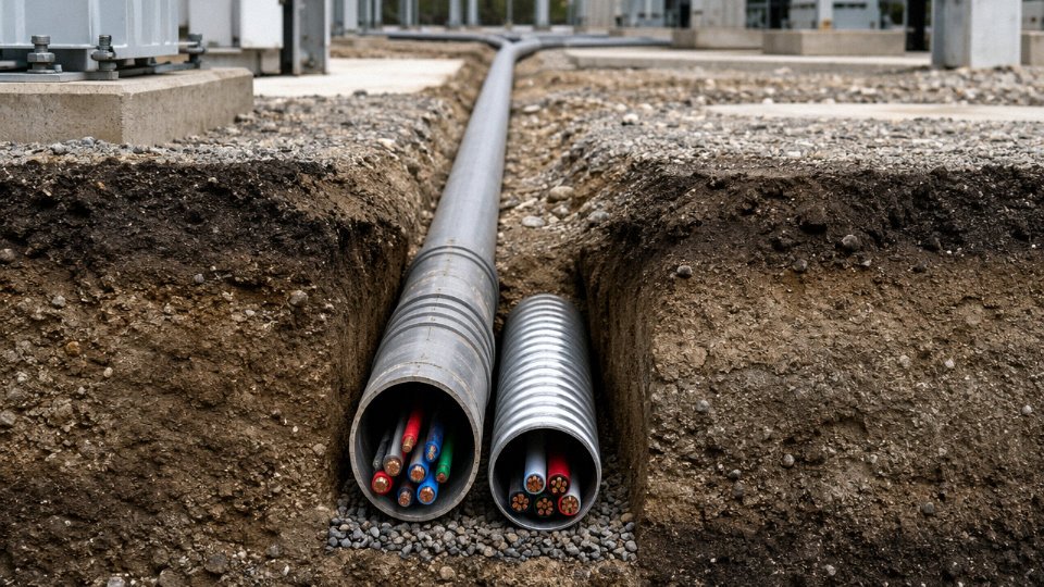
Sometimes — but the conditions are narrower than most contractors assume. NEC Article 300.5 does permit 300 mm cover for rigid metal conduit (RMC) or intermediate metal conduit (IMC) in specific locations, including certain under-slab configurations. That concession does not extend to open ground, unpaved driveways, or any surface where a spade could realistically reach the conduit during routine landscaping or utility work. Under roads carrying vehicle traffic, the NEC still requires 600 mm regardless of conduit type. IEC-based codes generally don’t offer the same shallow-conduit concession at all. The practical rule: always pull up the actual table from the standard governing your jurisdiction and identify the surface-type column before you decide the trench depth. A 300 mm trench that’s compliant under a concrete basement slab in one country may be a clear violation 10 meters away in the garden.
Does armor on a cable mean I can bury it shallower?
There is a depth credit available under some codes — BS 7671 Appendix 4 does recognize that steel wire armored (SWA) cable in a garden or low-traffic area can be installed at reduced depth compared to unarmored cable. In practice that credit is typically in the range of 50–100 mm, not enough to make a meaningful commercial difference to your trench cost. More critically, armor offers zero statutory depth relief under roads. The mechanical protection SWA provides is real — it resists incidental spade strikes and rodent damage — but the depth requirements under trafficked surfaces exist to protect against compressive loads that armor alone cannot withstand. Armor and depth are not substitutes for each other. Check clause-level guidance, not just the general rule.
What happens if a cable ends up buried too shallow after construction?
This is unfortunately common when other trades backfill a trench without realizing a cable crew had already laid and partially covered a run. Options, roughly in order of preference: re-excavate and re-lay at the correct depth; pour a reinforced concrete slab or cap over the shallow section to provide equivalent mechanical protection (this usually requires an engineer’s calculation and sign-off); or, where the loading analysis genuinely supports it, obtain a formal variance document with a risk assessment accepted by the authority having jurisdiction. What you cannot do is leave it shallow, cover it over, and say nothing — that creates both a safety liability and a contract issue if the cable fails and the installation records show non-compliance.
How deep for a garden or lawn?
Under BS 7671 and most IEC-derived national codes, 500–600 mm is the typical minimum for low-traffic domestic areas. Local distribution network operators (DNOs or utilities) sometimes impose their own requirements — 600 mm is common even in gardens under UK utility specifications — so check those separately from the wiring regulations. Armored cable and marker tape at 100–150 mm above the cable are strongly recommended at any depth in a garden. Future owners will dig for planting, and a warning tape has saved more cables than any other single precaution in domestic installations.
Is there a maximum burial depth?
No standard sets a formal upper limit. In practice, economic and ampacity considerations tend to cap direct burial at roughly 1,200–1,500 mm. Deeper than that, you’re usually better off installing a HDPE duct with a draw rope so the cable can be replaced without full excavation — because at that depth, re-excavation cost often exceeds the cable cost itself.
How do I verify depth before excavating near an existing cable?
Start with a CAT (cable avoidance tool) instrument and a signal clamp to induce a traceable signal onto the cable. That gives you route and estimated depth. Estimated. Before any mechanical equipment comes within 500 mm of the detected signal, hand-dig a series of inspection pits (potholing) to expose the cable and measure actual cover at intervals. Depth readings from a locator can be off by 20–30% depending on nearby metalwork and signal distortion — treat them as guidance, not measurement.
CAT locator depth readings can deviate significantly from actual burial depth due to electromagnetic interference from adjacent metalwork or parallel cables.True
Signal induction locators estimate depth from field geometry; parallel conductors, reinforcing steel, and multiple cables in the same route all distort the field and reduce depth accuracy. Physical exposure by hand-digging remains the only reliable verification method before mechanical excavation.
Does Jinda supply cables certified for direct burial in specific export markets?
Yes. Jinda’s armored LV cable range is type-tested to IEC 60502-1, which covers rated voltages up to 1 kV and is the baseline specification for direct burial in most IEC-jurisdiction countries. Beyond that, specific product families carry CE marking for European markets, SANS 1507 compliance for South Africa, and AS/NZS 5000.1 compliance for Australia and New Zealand. Getting the right certification matters for customs clearance, contractor compliance documentation, and insurance — not just for technical performance. Bring your project country, surface loading classification, and cross-section requirements to the Jinda technical team and they can match you to a compliant cable construction rather than leaving you to reverse-engineer the standard yourself.