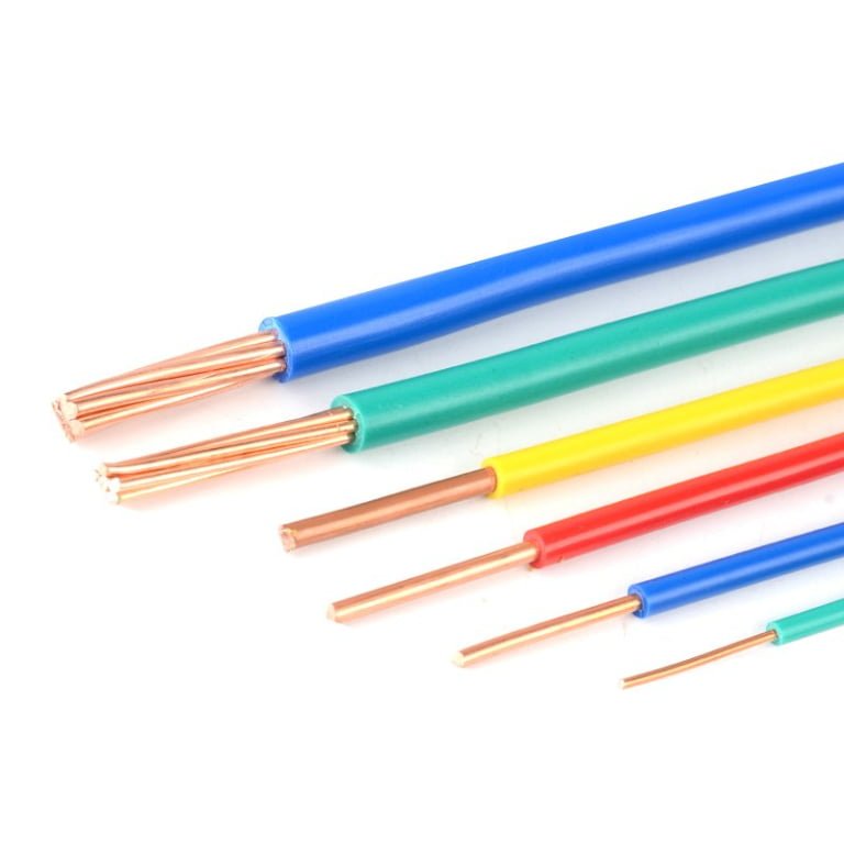
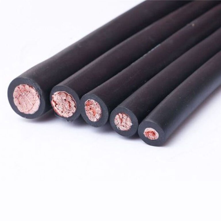
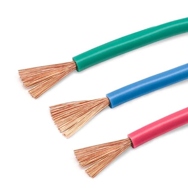
Cables that look identical on the shelf can behave completely differently once they’re installed in a moving application. Specify a rigid Class 1 or Class 2 conductor where the cable flexes repeatedly — a drag chain, a robotic arm, a festoon system — and you’re looking at work-hardening, conductor fatigue, and eventual strand fracture. That failure mode rarely announces itself cleanly; resistance climbs slowly, intermittent faults start appearing, and by the time someone pulls the cable and cuts into it, you’ve already lost hours of production tracing a problem that the wrong conductor class created from day one.
A Type 5 cable is a flexible electrical cable whose conductor is built to IEC 60228 Class 5, meaning it is made from a large number of fine stranded wires — for example, at least 30 individual wires in a 1.5 mm² conductor and at least 56 in a 4 mm² conductor — which allows it to bend repeatedly without fatigue, accept tighter installation radii (typically 4–6× the outer diameter versus 8–10× for rigid conductors), and maintain low DC resistance, staying at or below 13.3 Ω/km for 1.5 mm² and 7.98 Ω/km for 2.5 mm² at 20°C.
What most procurement specs don’t capture is that Class 5 isn’t just a flexibility rating — it’s a strand count discipline that affects everything downstream: termination method, ferrule sizing, current-carrying capacity derating, and even the insulation compound you can realistically extrude over fine wire bundles at production speed. The distinction matters more than it looks on a datasheet.
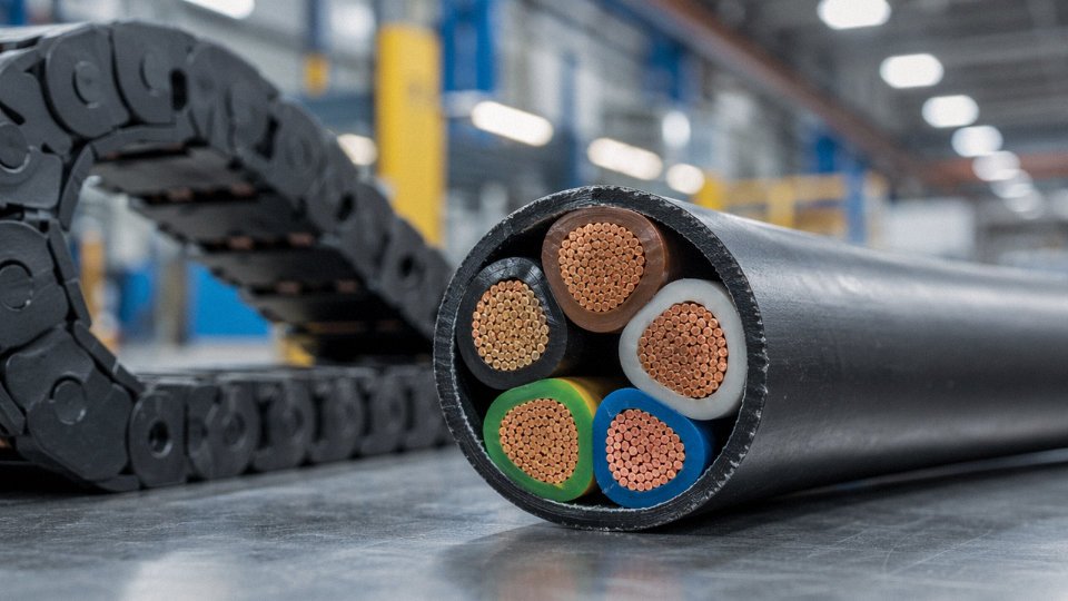
IEC 60228 Class 5 vs. Class 1, 2, 4, and 6: Technical Comparison You Can Use for Specification
Conductor class selection is where specifications go wrong most often — not in the insulation choice, not in the sheath compound, but in whether the engineer picked the right flexibility class for the actual installation. The IEC 60228 standard defines six conductor classes, and confusing them costs money. A Class 2 cable routed through a cable track that flexes 50 times a day will fail by work-hardening fracture within months. A Class 6 welding cable specified for fixed panel wiring is money wasted on fine-wire construction you don’t need. Class 5 sits in the middle of that range, and understanding exactly where it sits matters.
The Full Class Comparison in One Place
| Class | Conductor Form | Wire Count (e.g., 4 mm²) | Max DC Resistance at 20°C (4 mm²) | Intended Movement | Typical Cross-Section Range |
|---|---|---|---|---|---|
| 1 | Solid | 1 wire | ≤ 4.61 Ω/km | None — fixed only | 1–400 mm² |
| 2 | Standard stranded | ≥ 7 wires (4 mm²) | ≤ 4.61 Ω/km | Fixed installation, no flexing | 0.5–2500 mm² |
| 4 | Flexible stranded | ≥ 28 wires (4 mm²) | ≤ 4.70 Ω/km | Occasional repositioning | 0.5–300 mm² |
| 5 | Flexible stranded | ≥ 56 wires (4 mm²) | ≤ 4.70 Ω/km | Regular flexing, cable tracks, pendants | 0.5–300 mm² |
| 6 | Extra-flexible | Finer wires than Class 5 | ≤ 4.70 Ω/km | Continuous high-cycle bending | 0.5–120 mm² typically |
DC resistance limits for Classes 4, 5, and 6 at a given cross-section are identical under IEC 60228 — flexibility is achieved by subdividing wire count, not by reducing conductor area. The resistance advantage of Class 5 over Class 1/2 comes only when you move to larger cross-sections where solid or coarsely stranded conductors become impractical to terminate.
Class 1 and Class 2: Right for Fixed Wiring, Wrong Everywhere Else
Solid Class 1 conductors are fine for building wiring inside conduit or trunking where nobody is bending them after installation. They’re cheaper per meter and easier to terminate in screw terminals. But copper work-hardens — repeated bending forces dislocations through the crystal lattice until micro-cracks propagate and the conductor fractures. Even Class 2, which uses a small number of relatively thick strands, has poor fatigue resistance. In practice, Class 2 is acceptable for wiring inside a panel where cables are dressed once and never touched again. Route it through a drag chain and you’ll be chasing intermittent faults within a year.
Class 4: The Intermediate Option That’s Often Overlooked
Class 4 is genuinely useful for power cables on equipment that gets repositioned occasionally — think portable generators, temporary site power feeds, or equipment that moves monthly rather than daily. With roughly half the wire count of Class 5 at a given cross-section, it’s more flexible than Class 2 but cheaper to manufacture than Class 5. The reason Class 5 tends to win in modern specifications is fatigue life under repeated bending cycles. If there’s any chance the cable will flex regularly, the cost delta between Class 4 and Class 5 is small enough that most procurement managers just standardize on Class 5 and avoid the guesswork.
Class 6: Superior Flexibility, at a Price
Class 6 uses finer individual wire diameters than Class 5 — sometimes 0.1 mm or below per strand — which is why welding cables, festoon crane systems, and robotic arm wiring require it. The fine wires distribute bending stress across a far larger number of flex points, extending fatigue life dramatically under continuous high-cycle operation. That manufacturing complexity costs roughly 15–35% more per meter than equivalent Class 5 cable, depending on cross-section and copper pricing at the time. For a cable track on a machine that indexes 40 times per minute, Class 6 is correct. For a pendant control cable on an overhead crane that travels a few times an hour, Class 5 is almost always sufficient and will last the equipment’s service life without issue.
The Electrical Resistance Crossover — and Why Manufacturing Quality Matters
Because Class 5 subdivides the copper cross-section into many fine wires, skin effect at 50 or 60 Hz power frequencies is negligible — the skin depth in copper at 50 Hz is roughly 9–10 mm, far larger than any individual strand diameter. What does matter is wire-to-wire contact resistance and the conductor’s overall fill factor. A poorly compressed or unevenly stranded Class 5 conductor can show DC resistance that’s technically within spec but sits at the high end of the allowed band, which matters on long cable runs. Tight quality control on stranding pitch, lay ratio, and compaction is what separates Class 5 conductors that comfortably clear the IEC resistance limit from those that just squeak past it.
IEC 60228 Class 5 conductors at 4 mm² must achieve a minimum wire count of 56 individual wiresTrue
IEC 60228:2004 Table 5 specifies that Class 5 flexible conductors at 4 mm² nominal cross-section require a minimum of 56 wires, compared to a minimum of 7 wires for Class 2 at the same cross-section.
Annealed Copper: The Detail That Actually Determines Flex Life
IEC 60228 requires that Class 5 conductors use plain or tinned annealed copper — not hard-drawn wire. This distinction is critical and sometimes glossed over in commercial specifications. Wire drawing cold-works the copper: the crystal grains elongate and accumulate dislocations, raising tensile strength but drastically reducing ductility. Annealing — heating the drawn wire to roughly 200–400°C depending on the process, then controlled cooling — allows recrystallization. New equiaxed grains form, dislocations annihilate, and the copper recovers elongation values typically in the 20–30% range. Without that step, a conductor made from hard-drawn wire might meet the DC resistance specification on day one but will crack under flex cycling far earlier than IEC-compliant annealed wire. When auditing a supplier, ask specifically for the annealing process parameters and incoming copper rod elongation test data. It’s the single most overlooked quality checkpoint in Class 5 conductor manufacturing.
How Type 5 Cables Are Manufactured: Wire Drawing, Stranding, and Conductor Assembly
Manufacturing a Class 5 conductor that actually performs in continuous flexing service — rather than just passing a resistance test on a spool — comes down to process discipline at three stages: wire drawing, annealing, and stranding. Cut corners at any one of them and the cable will survive commissioning but fail in service, usually at the worst possible time.
Wire Drawing: From Rod to Fine Wire
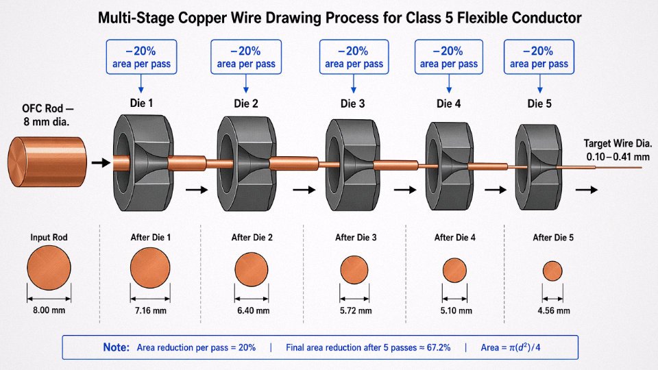
The process starts with oxygen-free copper rod, typically 8 mm diameter, produced via continuous casting. Oxygen-free rod matters because residual oxygen forms Cu₂O grain-boundary inclusions that cause wire breaks during drawing at fine gauges — a problem you won’t always catch during incoming inspection but will absolutely see as die-wear patterns and wire breaks on the drawing machine.
The rod is drawn down through a sequence of tungsten carbide dies, each reducing the cross-sectional area by roughly 15–25% per pass. Depending on the target wire diameter and the total reduction ratio required, this can mean anywhere from 12 to 25 die passes. For Class 5, individual wire diameters typically land between 0.10 mm and 0.41 mm depending on the conductor cross-section and the wire count needed to meet IEC 60228 minimums — 30 wires at 1.5 mm², 56 wires at 4 mm², 126 wires at 16 mm², and so on upward. Fine wire drawing at 0.10–0.15 mm is genuinely demanding; die alignment, lubricant temperature, and spool tension all interact. A poorly maintained drawing line will produce wires with diameter variation across the spool that causes resistance non-uniformity across the finished cable length.
Annealing: The Step That Determines Flexibility
Cold-drawn copper is work-hardened and brittle. Without proper annealing it will crack under repeated bending, full stop. Two methods are used in practice: batch (bell) annealing in a controlled-atmosphere furnace, and continuous inline annealing integrated directly into the drawing line via a resistance-heating or induction section. Inline annealing is faster and more consistent for high-volume fine wire production; batch annealing gives more process flexibility for special alloys or thicker gauges but requires careful temperature uniformity across the furnace load.
The target is minimum elongation at break of ≥20% for fine wires meeting IEC 60228 Class 5. Underannealed wire — a common consequence of rushing cycle times or running furnace loads too dense — will measure close to spec in tensile strength but fail the elongation test and, more importantly, crack after a few hundred flex cycles in the installed cable. This is the failure mode that causes “premature” flex cable failures that plant maintenance teams often blame on the application rather than the conductor manufacturing.
IEC 60228 Class 5 requires a minimum elongation at break of 20% for fine copper wiresTrue
IEC 60228 specifies minimum elongation requirements for annealed conductors; fine wires in Class 5 flexible conductors are expected to meet ≥20% elongation at break, which is a standard acceptance criterion in conductor manufacturing and testing.
Stranding: Bunching vs. Concentric Lay
Class 5 conductors are built using one of two stranding geometries, and the choice matters operationally. Concentric (rope-lay) stranding arranges wires in defined layers with alternating lay direction; this is preferred for larger cross-sections, say 16 mm² and above, where geometric stability and predictable resistance are priorities. Bunch stranding — where wires are twisted together without a precise geometric pattern — is common for fine flexible conductors at smaller cross-sections. It’s faster to produce and gives slightly better flex life in some orientations, but conductor diameter can be less consistent and the bundle is harder to terminate cleanly if the installer is careless.
Lay length is a real trade-off. Shorter lay lengths improve flexibility but marginally increase conductor resistance because each wire travels a longer helical path. In practice, the optimization sits somewhere between 8× and 16× the conductor pitch diameter for typical Class 5 flexible applications, though the right number depends on the flex cycle count requirement and the insulation system being applied over the conductor.
Tinning Options and Resistance Implications
Tinned conductors are specified when the cable will be used with high-temperature insulation materials (silicone rubber, PTFE), in aggressive chemical environments where bare copper would corrode at the wire surfaces and cause inter-strand oxidation, or where the conductor ends will be soldered rather than crimped. Both hot-dip tinning — where wires pass through a molten tin bath during drawing — and electrolytic tinning are used. Hot-dip tinning gives a thicker, more uniform coating but can change wire diameter slightly; electrolytic is more precise and better for very fine wire gauges.
The resistance penalty is small but real. A fully tinned Class 5 conductor typically runs 2–4% higher DC resistance than an equivalent bare copper conductor, because tin has roughly 6–7× the resistivity of copper and the coating effectively reduces the copper cross-section slightly. For most applications this is negligible. In a high-ampacity busbar feeder where you’re running near the continuous rating, it’s worth checking against the ≤1.91 Ω/km limit at 10 mm² — though in practice tinned conductors at that size are unusual.
Quality Control at Each Stage
Laser micrometers on the drawing line provide continuous wire diameter measurement — not sample-based, continuous — which is the only practical way to catch die wear before it produces out-of-tolerance wire across a full production drum. Finished conductor resistance is measured per IEC 60228 at 20°C before insulation extrusion. Strand count and conductor diameter are verified per reel. For export production, flex-cycle fatigue testing on finished cable samples is run to confirm that the annealing and stranding parameters hold up in the application, not just in the raw wire test.
Jinda’s five production bases across China, covering 470,000 m² of manufacturing space, include dedicated fine wire drawing lines and multi-stage stranding equipment sized for consistent Class 5 production at volume. In-house testing laboratories are calibrated to IEC standards, which matters for international export documentation — a third-party test report from a lab that doesn’t have traceability to the IEC reference standards is worth less than it looks on paper. For bulk procurement programs, process consistency across a large production run is ultimately what separates a reliable supply partner from a supplier that passes the sample inspection and then drifts.
Insulation and Jacket Materials Paired with Class 5 Conductors: PVC, XLPE, Rubber, and Beyond
IEC 60228 stops at the conductor. It governs how many wires make up a 1.5 mm² or 16 mm² conductor, what the maximum DC resistance must be, and how the strands are assembled — nothing more. The moment you step off the manufacturing floor with a finished cable, you’re working under a completely different set of standards: IEC 60227 for PVC flexible cables, IEC 60245 for rubber-insulated flexible cables, and a range of product-specific standards beyond those. A Class 5 conductor is a starting point, not a finished specification. The insulation compound, the jacket material, any shielding layers, and the applicable product standard together determine what temperature the cable can actually handle, whether it survives oil splash or UV exposure, how it behaves at −30°C in an outdoor Nordic installation, and whether it passes the regulatory checks your end customer requires.
PVC: Workhorse Pairing, With Real Limitations
PVC-insulated Class 5 cable is the default choice across most commercial and light industrial work. It’s inexpensive relative to alternatives, color-coding is straightforward (the IEC color palette is well-supported by PVC compounders), and continuous service at 70°C covers a wide range of building and panel wiring applications. For most procurement managers sourcing general-purpose flexible cable, PVC covers roughly 60–70% of use cases without much debate.
The problem shows up in winter, or in cold storage facilities. Standard PVC gets stiff — genuinely stiff, to the point where installers curse it — at temperatures below around −15°C to −20°C, and some cheaper plasticizer packages start showing brittleness even at −10°C. Cold-flexible PVC compounds (sometimes marketed as “Arctic” or “cold-weather” grades) extend usable range down to −30°C or so, but you need to explicitly specify this. Don’t assume it’s included because it’s not.
XLPE: Where Higher Current Density Matters
Crosslinked polyethylene bumps the continuous temperature rating to 90°C, which in practical terms means you can run more current through the same conductor cross-section — or downsize the conductor while maintaining the same rating. XLPE also has a lower dielectric constant than PVC, which matters for longer cable runs where capacitive effects become meaningful, and its chemical resistance is noticeably better. In industrial power flex applications — think motor feeds on automated production lines — XLPE-insulated Class 5 cable is increasingly the engineer’s first choice where the extra cost is justified by the thermal headroom.
XLPE insulation allows higher current ratings than PVC for the same conductor cross-section due to its higher temperature rating.True
Current-carrying capacity tables in IEC 60364-5-52 and similar standards assign higher ampacity values to 90°C-rated conductors compared to 70°C-rated PVC conductors of identical cross-section, under equivalent installation conditions.
Rubber Compounds: When Flexibility and Harsh Environments Are Non-Negotiable
EPR (ethylene propylene rubber) is the standard choice for mining cables, marine portable power, and any application where the cable is routinely dragged across rough surfaces in cold conditions. It maintains genuine flexibility down to −40°C and handles mechanical abuse that would crack PVC-insulated cable in a single shift. CSP — chlorosulfonated polyethylene, historically known by the trade name Hypalon — adds ozone and UV resistance on top of EPR’s mechanical properties, making it the go-to jacket for outdoor portable equipment and cables exposed to weathering over years.
Silicone rubber is a different category entirely. Ratings of 150°C to 180°C are typical, with some specialty compounds going higher. You see it in furnace wiring, industrial ovens, and aerospace harnesses. It’s expensive and somewhat mechanically fragile compared to EPR, so it doesn’t belong in drag-chain or high-abrasion environments regardless of temperature requirements.
TPE and PUR: The Machine-Tool Standard
Polyurethane (PUR) jackets over Class 5 cores have essentially become the default specification for drag-chain cables and machine tool wiring in European machinery manufacturing. The abrasion resistance is genuinely exceptional — in controlled flex testing, PUR-jacketed cables typically outlast PVC equivalents by a wide margin in continuous flex applications. Oil resistance is strong enough for most machining-center environments. TPE compounds offer similar performance in many cases and carry a recyclability advantage over thermoset rubbers, which matters for procurement teams working toward end-of-life material recovery commitments.
Shielding Layers and Their Effect on Flex Performance
Layering shielding over insulated Class 5 cores adds EMI rejection but always affects bend radius and flex life — a tradeoff worth understanding before specifying. Braided copper shields handle repeated flexing reasonably well and provide good low-frequency EMI attenuation, suitable for most industrial control cables. Foil (aluminized polyester) plus a drain wire gives better high-frequency rejection and is lighter and thinner, but the foil itself is less tolerant of repeated tight bending — it work-hardens and eventually cracks. Spiral (serve) shields sit between the two: more flex-tolerant than foil, less shielding effectiveness than braid, but often the right answer for drag-chain applications where the cable flexes millions of cycles and moderate shielding is sufficient. Specify the wrong shield construction for a drag-chain application and you’ll be replacing cables within months rather than years.
Application Map: Where Type 5 Flexible Cable Is the Correct and Required Choice
Knowing the strand count and resistance figures is necessary, but it doesn’t answer the real question on the plant floor: where does Class 5 actually belong, and where are you wasting money by over-specifying flexibility you don’t need? The answer cuts across sectors in ways that aren’t always obvious from reading the standard alone.
Industrial Machinery and Factory Automation
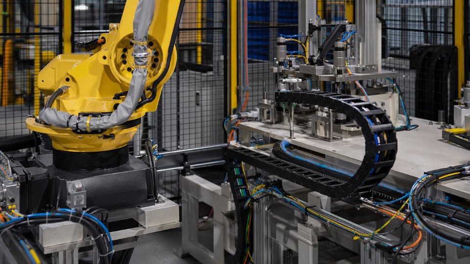
This is the heartland of Class 5 cable. Machine tools, robotic work cells, conveyor drive cabinets, and servo motor connections all subject their cables to continuous, repetitive movement — sometimes millions of flex cycles over a machine’s service life. A rigid Class 1 or Class 2 conductor will work-harden at the bend point and fracture internally long before any visible jacket damage appears. The failure mode is insidious: intermittent continuity faults that show up as random drive trips, which maintenance teams often chase for days before finding the broken conductor strand.
For servo and encoder cables, specify Class 5 with a PUR (polyurethane) outer jacket and individually shielded pairs. PUR handles hydraulic oil splash and the mechanical abrasion from cable tracks far better than standard PVC. For general machine wiring that sees oil mist rather than direct immersion, Class 5 with an oil-resistant PVC jacket per IEC 60227 designation codes is usually adequate and considerably cheaper.
Building Services and Portable Power Distribution
IEC 60227-4 and IEC 60227-5 designate H05VV-F and H07VV-F cable types — both built on Class 5 conductors — as the standard for domestic appliance leads, extension cords, and portable power distribution on construction sites. The flexibility here isn’t about repeated mechanical cycling; it’s about handling during installation and the need for a cable that can be coiled, routed around corners, and plugged in without fatiguing the conductor at the terminal.
There’s a practical ampacity point worth knowing. In conduit, a flexible Class 5 conductor fills the cross-section more uniformly than a Class 1 solid wire, which can produce marginally better thermal contact with surrounding conductors and conduit fill. The difference is small, but it occasionally matters when a specifier is borderline on a conduit fill calculation and reluctant to upsize.
Renewable Energy and Solar Installations
DC string cables running from panel junction boxes to combiner boxes often use Class 5 conductors inside XLPE-insulated, UV-stabilized double-insulated constructions per IEC 62930 (the EN 50618 H1Z2Z2-K designation is the one you’ll actually see on cable drums in Europe). The flexibility matters most during installation — roof surfaces are uneven, panel arrays require cables to be looped and dressed by hand, and installers working quickly will bend cables into tight radii without much thought. A Class 5 conductor tolerates that; a Class 2 conductor in the same situation can develop micro-cracks at the strand level before the system is even energized.
IEC 62930 / EN 50618 H1Z2Z2-K solar cable specifications require Class 5 conductors to provide adequate flexibility during installation on uneven roof and ground-mount surfaces.True
IEC 62930 (identical to EN 50618) specifies flexible conductors (Class 5 per IEC 60228) for photovoltaic system cables precisely because installation on uneven surfaces requires a conductor that tolerates tight bending without strand fracture.
Marine and Offshore Applications
IEC 60092 is the governing series for shipboard electrical installations, and it is unambiguous: portable equipment and shore power connections require flexible conductors. Class 5 is mandatory in these roles. Flag state regulations — and most classification societies including Lloyd’s, DNV, and Bureau Veritas — additionally require halogen-free, flame-retardant sheathing, because smoke toxicity in an enclosed vessel is a life-safety issue, not just a property damage concern. Specifying a standard PVC-sheathed flex here is a compliance failure, not a cost saving.
Mining and Heavy Industry
Trailing cables for continuous miners, mobile crushing plant, and portable substations live hard lives. They get dragged across broken rock, run over by equipment, and coiled in wet sumps. Class 5 or Class 6 conductors inside heavy-wall rubber sheathing per IEC 60245 or applicable national mining standards handle this environment because the stranding allows the conductor to distribute mechanical stress across hundreds of wires rather than concentrating it. Class 5 is usually the procurement default; Class 6 is specified when the equipment manufacturer explicitly requires it or when very tight minimum bend radii are unavoidable.
Data Centers and Low-Voltage Infrastructure
Patch leads, power whips, and PDU branch cables in data center environments get moved. Rack equipment gets swapped out, cable managers get reorganized, and over a five-to-ten-year service life the cumulative handling adds up. A Class 1 solid conductor in that environment will eventually develop hairline fractures at crimp terminations and connector entries — not from a single event but from repeated small deformations. Class 5 conductors don’t work-harden the same way. For anyone specifying or procuring PDU cables, power whips, or any flexible power distribution element in a high-density compute environment, Class 5 is simply the correct choice, and the cost premium over equivalent solid-conductor cable is negligible at the cross-sections involved (typically 1.5 mm² to 6 mm²).
International Standards and Approvals That Govern Type 5 Cable Products: IEC, UL, VDE, and Regional Requirements
IEC 60228 as the Foundation Layer
Before any country-specific approval matters, IEC 60228 Class 5 compliance has to be established. Every downstream product standard that references flexible conductors — whether it’s a European harmonized specification, a UL category, or a Gulf-region adoption of British Standards — either directly cites IEC 60228 or runs parallel conductor requirements that functionally mirror it. You cannot substitute regional approval for this foundation. A VDE certificate doesn’t override IEC 60228; it supplements it, adding test requirements for the finished cable on top of a conductor that was already built to Class 5 geometry and resistance limits.
In practical procurement terms: if a supplier cannot produce a test report showing conductor resistance at 20°C at or below the IEC 60228 Class 5 limits (1.91 Ω/km for 10 mm², 7.98 Ω/km for 2.5 mm², and so on), no downstream approval certificate is worth the paper it’s printed on.
Decoding the IEC 60227 and IEC 60245 Designation System
IEC 60227 covers PVC-insulated cables; IEC 60245 covers rubber-insulated cables. Both use a structured alphanumeric designation that tells you everything you need to know — once you know how to read it.
Take H05VV-F and H07RN-F as the two workhorses most purchasing managers encounter:
- H = harmonized cable type (recognized across EU member states)
- 05 / 07 = voltage rating: 05 means 300/500 V, 07 means 450/750 V
- V / R / N = insulation or sheath material: V is PVC, R is rubber, N is neoprene (polychloroprene)
- F = flexible stranded conductor (Class 5)
- The trailing numbers indicate core count and cross-section, e.g., 3G2.5 means 3 cores, 2.5 mm², with a green/yellow earth
H07RN-F is the cable you find on construction site distribution boards, portable generator sets, and heavy workshop equipment — rubber insulation, 450/750 V, Class 5 flex conductor. H05VV-F shows up in lighter industrial applications and appliance leads. Getting the designation wrong in a specification leads to either an underrated cable in the field or unnecessary cost from over-specification.
European Approvals: VDE, KEMA/DEKRA, BASEC, and the HAR Mark
CE marking under the Low Voltage Directive (2014/35/EU) is mandatory for cables sold into EU markets, but CE alone is a manufacturer’s self-declaration. What actually carries weight with specifiers is third-party certification from a notified body — VDE in Germany, KEMA/DEKRA in the Netherlands, BASEC in the UK.
The HAR harmonization mark on a cable drum indicates that the cable was manufactured to a harmonized European standard and certified by a recognized national testing body within the HAR scheme. In practice, a drum marked with the HAR lozenge can be sold across all participating European countries without re-testing. For procurement managers sourcing cable for projects spanning multiple EU countries — a common situation in infrastructure, renewables, and industrial automation — a single HAR-certified product simplifies approval paperwork considerably.
Post-Brexit, BASEC certification no longer automatically grants EU market access, though it remains the standard for UK projects. Buyers supplying both markets typically need to verify that their cable supplier holds both BASEC and a continental HAR-scheme certification.
North American Market: UL and CSA
UL and CSA certification is where IEC-familiar engineers hit friction. UL 62 covers rubber-insulated flexible cables and cords; UL 66 covers thermoplastic-insulated flexible cords. The Canadian equivalent is CSA C22.2 No. 49. The underlying test methodology overlaps substantially with IEC, but there are real differences:
- UL uses AWG cross-sections, not IEC mm² values. A 12 AWG conductor is roughly 3.31 mm², which doesn’t map cleanly to the IEC 2.5 mm² or 4 mm² sizes. This matters when substituting products or comparing resistance specifications.
- UL conductor flexibility categories don’t use the Class 1–6 IEC nomenclature. “Extra-flexible” UL cord types approximate Class 5, but a direct claim of equivalency needs to be backed by test data, not just a label comparison.
A cable with IEC 60228 Class 5 conductor construction is automatically UL-listed for flexible cord applications.False
IEC 60228 and UL listing are separate certification processes with different test protocols and administrative requirements. IEC Class 5 construction is necessary but not sufficient for UL listing; the cable must be separately submitted to and approved by UL under the relevant category (UL 62 or UL 66).
Jinda supplies cables certified under both IEC-based harmonized standards and UL/CSA categories, which matters for export-oriented manufacturers and OEM buyers shipping finished equipment to multiple markets.
Middle East, Southeast Asia, and Africa
SASO (Saudi Arabia), SIRIM (Malaysia), KEBS (Kenya), and SABS (South Africa) each have their own regulatory frameworks, but in practice most of them either adopt IEC standards directly or base their national standards on IEC or British Standards. The result: a cable with solid IEC 60228 Class 5 conductor compliance plus a VDE or BASEC product certificate is broadly accepted across these markets, usually with a local type-approval registration step rather than full re-testing.
The Gulf Cooperation Council’s ESMA and SASO schemes have been tightening import controls over the past several years. Documentation requirements — test reports, factory audit certificates, country-of-origin declarations — are increasingly rigorous. Suppliers who can produce a full documentation package upfront reduce clearance delays significantly.
Factory Certification and Third-Party Audit Requirements
Product approvals only answer part of the question. International buyers awarding long-term supply contracts typically require ISO 9001 quality management certification and ISO 14001 environmental management certification at the factory level, plus the option to conduct or commission third-party factory audits through SGS, Bureau Veritas, or Intertek.
This is where supplier infrastructure matters. A manufacturer operating across five production bases, as Jinda does, needs consistent quality management systems across all sites — a single ISO 9001 certificate covering a head-office operation while other sites run unaudited is a red flag worth probing during due diligence. Jinda’s quality infrastructure spans its full manufacturing footprint, which means the audit findings at one site are representative of actual production capability rather than a showroom exercise.
In my experience, the buyers who skip the factory audit step — relying solely on certificates — are the ones who end up with quality inconsistencies on the fourth or fifth shipment. Certificates tell you what a supplier was capable of on a particular test date. Audits tell you whether they can repeat it.
Specifying and Ordering Type 5 Cable: A Practical Guide to Cross-Section Selection, Current Ratings, and Derating
Starting from Load Current and Working Backward
The right sequence for cross-section selection is load first, installation conditions second, derating third. Start with the design load current, then find the base current-carrying capacity for your conductor in the applicable IEC 60364-5-52 installation method — buried, in free air, on a tray, clipped to a surface, in conduit. Each method has a different base rating because it affects how efficiently the cable sheds heat.
Grouping derating is where most specifiers underestimate the correction needed. When you bundle Class 5 flexible cables together in a drag-chain or cable tray, each cable raises the ambient temperature around its neighbors. IEC 60364-5-52 Table B.52.17 gives grouping factors; for a group of five cables touching in a horizontal tray, the factor is typically in the range of 0.60–0.75 depending on arrangement — meaning you may need to upsize by one or two cross-section steps.
Worked example. A 16 A circuit runs as one of five cables inside a drag-chain, PVC-insulated, ambient 40°C. Base tabulated capacity for 2.5 mm² in enclosed conditions is roughly 18–20 A before correction. Apply a grouping factor of around 0.68 (five cables, enclosed, touching) and an ambient correction for 40°C of approximately 0.87: effective capacity ≈ 20 × 0.68 × 0.87 ≈ 11.8 A. That’s below 16 A, so 2.5 mm² is undersized. Moving to 4 mm² gives a base of roughly 25–27 A, yielding an effective capacity around 14.8–15.9 A — still marginal. In a real drag-chain with thermal buildup, 6 mm² is the defensible choice. Many engineers stop at the first derating step and miss the second. Don’t.
Cross-Section Range and the Semi-Flexible Reality
IEC 60228 Class 5 is defined from 0.5 mm² up to 2500 mm², but commercially available flexible Class 5 cable in standard catalog stock concentrates between 0.5 mm² and 240 mm². Above roughly 95 mm², the conductor transitions to rope-stranded construction — multiple bunched strands rather than a single fine-wire assembly — and the cable becomes semi-flexible at best. You can still bend it on installation, but don’t expect it to survive a drag-chain or repeated dynamic flex at those sizes. For large cross-sections in genuinely flexible applications, consult the manufacturer about special bunched-rope constructions; it’s a different product family.
Voltage Drop Calculation
Because IEC 60228 specifies maximum DC resistance for Class 5 conductors at 20°C, voltage drop is calculable before you order. For single-phase:
V_drop = I × R × L × 2
where R is conductor resistance in Ω/m and L is run length in meters.
| Cross-section | Max DC resistance (Ω/km, 20°C) | Voltage drop (V per A per 100 m, single-phase) |
|---|---|---|
| 1.5 mm² | ≤ 13.3 | ≤ 2.66 |
| 2.5 mm² | ≤ 7.98 | ≤ 1.60 |
| 4 mm² | ≤ 4.95 | ≤ 0.99 |
| 6 mm² | ≤ 3.30 | ≤ 0.66 |
| 10 mm² | ≤ 1.91 | ≤ 0.38 |
| 16 mm² | ≤ 1.21 | ≤ 0.24 |
For a 20 A load on a 50 m single-phase run in 2.5 mm²: V_drop = 20 × 0.00798 × 50 × 2 = 15.96 V. That’s over 7% on a 230 V system — well outside the 4% limit common in European industrial practice. Upsize to 6 mm² and the same run drops to about 6.6 V, which is acceptable.
Temperature Correction for Resistance
IEC 60228 resistance limits are stated at 20°C. A cable running continuously at 70°C in a warm enclosure has higher actual resistance. The correction uses the copper temperature coefficient α = 0.00393 per °C:
R_T = R_20 × [1 + 0.00393 × (T − 20)]
At 70°C, the multiplier is 1 + 0.00393 × 50 = 1.197 — nearly 20% higher resistance than the 20°C figure. At 90°C continuous, you’re looking at roughly 1.28×. For voltage-drop-critical circuits or precision heating loads, this correction isn’t optional. It’s often ignored on short runs and becomes a real problem on long supply cables to sensitive equipment.
IEC 60228 resistance values are specified at 20°C and must be temperature-corrected for accurate voltage drop calculations at operating temperature.True
IEC 60228:2004 Section 3 states that resistance limits apply at 20°C, and correction using the copper temperature coefficient is standard practice per IEC 60287 and IEC 60364 application guidance.
Mechanical Specification Checklist
Before finalizing a specification, work through these in order — skipping any one of them is where cables fail in service:
- Bend radius: Class 5 typically allows installation radii of 4–6× cable outer diameter; dynamic flex applications in drag-chains require specific ratings from the cable manufacturer, usually confirmed at a defined cycle count
- Flex cycles: State the required service life cycles explicitly — 1 million cycles for a light-duty machine tool and 5 million for a high-speed automation axis are very different constructions
- Environmental exposure: UV, cutting oils, coolants, hydraulic fluid, abrasion from cable carrier contact — each narrows the insulation and jacket selection
- Temperature range: Minimum installation temperature matters; PVC-jacketed cable below −10°C can crack during laying. Maximum continuous operating temperature drives insulation class
- Flame and smoke requirements: IEC 60332-1 (single vertical), IEC 60332-3 (bunched), IEC 61034 (smoke density), IEC 60754 (halogen-free) — know which apply before specifying compound
Ordering Information for Bulk and Export Projects
Type 5 flexible cable is highly customizable, which means ambiguous purchase orders create delays. To get a fast, accurate quotation from Jinda’s technical team, provide: conductor cross-section and IEC 60228 Class 5 confirmation; number of cores (Jinda’s range runs from 2 to 60+ cores for multicore flexible constructions); shielding requirements (unshielded, foil, braid, or combination); insulation and jacket material with temperature rating; jacket color and any core identification standard (number printed, color-coded, or both); drum or reel lengths; and any country-specific certifications needed — VDE, HAR, CE, or others.
Surface-level specs get surface-level responses. The more precisely you define the mechanical and environmental requirements upfront, the shorter the back-and-forth before production approval. That matters on large export orders where lead time starts when documentation is complete.
Quality Pitfalls and How to Verify Type 5 Cable Compliance Before Shipment
The Class 5 label is easy to print. The conductor underneath is harder to fake — but plenty of suppliers try anyway. For procurement teams buying flexible cable at volume, especially across international supply chains, the gap between a compliant reel and a substandard one is not visible until the cable is already installed, drawing current, and heating up.
The Most Common Fraud: Strand Count Substitution
Reducing wire count is the cheapest way to shave copper cost while keeping the outer diameter plausible. A manufacturer draws thicker wires, bundles fewer of them, and calls it Class 5. The resulting conductor looks and measures close to the right cross-section — sometimes within a millimeter or two on OD — but the flexibility and fatigue life are closer to Class 2 or Class 4.
Detection is straightforward if you have ten minutes and a loupe. Request a conductor cross-section sample — a clean transverse cut through the conductor — and count the individual wires. IEC 60228 sets minimums: 1.5 mm² requires at least 30 wires, 4 mm² at least 56, 16 mm² at least 126. If a supplier’s sample falls short, that’s your answer.
A faster field check: measure DC resistance with a calibrated bridge or microhmmeter and compare against IEC 60228 Class 5 maximums. At 20°C, 2.5 mm² must read no higher than 7.98 Ω/km and 10 mm² no higher than 1.91 Ω/km. A coarser conductor with fewer, thicker wires will typically read higher resistance than a properly stranded Class 5 because individual wire work hardening and contact geometry differ. Not always dramatically, but measurably.
Undersized Cross-Section
This one causes fires. A declared 2.5 mm² conductor that actually measures 2.2 mm² carries roughly 12–15% more resistance per meter than specified. In a circuit running near rated current continuously — a motor drive cable, a machine tool feeder — that translates directly to heat. IEC 60228 permits a small minus tolerance on conductor area as inferred from resistance measurement, roughly −3%, but genuinely substandard products often run 8–15% light. At that point you’re outside any tolerance band and into misrepresentation.
Have your inspector pull a 1-meter sample, strip insulation, and perform a gravimetric cross-section measurement or a precision resistance measurement. Both methods work. If the resistance-derived cross-section is more than 3% below nominal, reject the reel.
Insulation Thickness Violations
IEC 60227 (PVC) and IEC 60245 (rubber) both specify minimum average and minimum point insulation thickness indexed to voltage class and conductor size. Thin spots matter more than average wall because dielectric breakdown initiates at the thinnest point. Request the insulation thickness measurement report from the factory test certificate — a legitimate manufacturer records both average and minimum spot values per core. Cross-check those numbers against the applicable standard table. If the supplier cannot produce that report, that absence tells you something.
Third-Party Pre-Shipment Inspection
For any order above roughly 5,000–10,000 meters, the cost of an SGS, Bureau Veritas, or Intertek inspection at the factory or load port is trivial against the cost of installed-and-failed cable. A practical protocol covers: dimensional checks (OD, insulation wall, sheath wall) with calibrated digital micrometers; DC resistance per IEC 60228; 100% spark test confirmation from production records; and a destructive sample check on strand count and conductor cross-section. Specify these in your purchase order as a shipment condition, not as an optional add-on.
Certificate Verification
VDE, UL, and BASEC certificates can be independently verified online without contacting the supplier.True
VDE certificates are searchable at the VDE CERTIPEDIA portal by certificate number. UL certifications are verifiable via UL Product iQ. BASEC maintains a publicly accessible certified products list at basec.org.uk. Cross-checking a certificate number against these databases takes under two minutes and catches photocopied or expired documentation immediately.
Never accept a certificate as a scanned PDF alone. Certificate numbers can be typed into the VDE CERTIPEDIA portal, UL Product iQ, or the BASEC certified products list in under two minutes. If the number returns no result, or returns a different product family or manufacturer name, the document is at minimum outdated and possibly fabricated.
Jinda’s Internal Quality Assurance Workflow
Incoming copper rod is tested for conductivity and cross-section before it reaches the drawing line — substandard rod is a common upstream source of resistance non-conformance that manufacturers running volume on thin margins tend to skip. During stranding, resistance is measured in-process at intervals tied to reel length, not just at end-of-line. Every insulated conductor passes 100% spark testing before jacketing. Final routine test certification accompanies each drum shipment, with test methods referenced to IEC 60228 for conductor resistance and IEC 60811 for insulation and sheath mechanical properties. Those test records are available to buyers on request, not buried in a quality manual.
In practice, the difference between a compliant supplier and a cost-cutting one shows up in these records. Ask for them early — a supplier reluctant to share incoming copper test data and in-process resistance logs is telling you something about where they cut corners.
Frequently Asked Questions About Type 5 Cable
Is Type 5 cable the same as Class 5 cable?
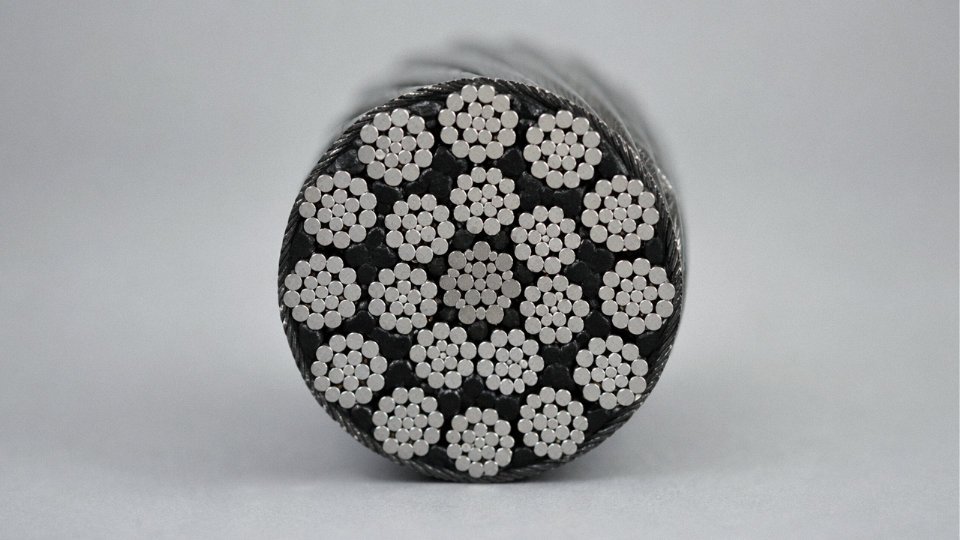
Yes, completely. “Type 5” and “Class 5” describe the same conductor construction defined in IEC 60228. The formal standard uses “Class 5” throughout, but trade catalogues, drum labels, and distributor price lists across Europe, the Middle East, and Southeast Asia routinely say “Type 5” — it’s the same product. If a supplier datasheet says Type 5 and references IEC 60228, you’re reading about a Class 5 conductor: flexible, stranded copper, with minimum wire counts (≥30 wires at 1.5 mm², ≥56 at 4 mm², ≥126 at 16 mm²) and maximum DC resistance limits enforced at 20°C. The terminology confusion mostly catches out procurement teams working across regions where one term dominates. Electrically and mechanically, there is no difference.
What is the difference between Class 5 and Class 6 flexible cable?
Both classes use fine stranded copper and are genuinely flexible — but Class 6 pushes further. Individual wire diameters in a Class 6 conductor are smaller still, which delivers meaningfully higher flex-cycle life. For welding cable, robotic arm cabling, or festoon systems on overhead cranes running millions of bend cycles per year, Class 6 is the right call. Class 5 is sufficient — and the more economical choice — for machine tool wiring, portable power equipment, extension leads, and control cabinet assembly where flexing is moderate or occasional. Using Class 6 where Class 5 is adequate costs more without any functional gain. Going the other way, specifying Class 5 on a continuous-flex robotic tow chain will eventually show up as broken wires and intermittent faults, usually at the worst possible time during a production run.
Can Type 5 cable be used in fixed installation wiring?
Yes, and it often makes sense. IEC 60364 permits Class 5 flexible conductors in fixed installations without restriction. In control panel and switchgear cabinet wiring, many experienced panel builders actually prefer Class 5 over Class 1 or 2 specifically because the stranded conductor is far easier to route, terminate into ferrules, and reposition during maintenance without risk of snapping individual wires. Rigid Class 1 conductors in a busy cabinet can work-harden at terminal entries after a few re-terminations. Class 5 tolerates that much better.
What current does a 2.5 mm² Type 5 cable carry?
This depends on installation method, insulation material, grouping, and ambient temperature — not on conductor class. A 2.5 mm² Class 5 PVC-insulated cable in free air at 30°C will typically carry somewhere in the range of 24–27 A under IEC 60364-5-52 reference conditions. Group it with several other loaded cables in a conduit at 45°C ambient, and that figure can drop to 16–18 A or lower. The conductor class does not change the current rating; the installation conditions do. Always apply the relevant derating factors before sizing.
Does strand count affect electrical resistance?
Not directly. The cross-sectional area governs resistance. IEC 60228 sets the same maximum DC resistance limit for a given nominal cross-section regardless of class — a 10 mm² Class 2 and a 10 mm² Class 5 conductor both sit at ≤1.91 Ω/km at 20°C. More strands mean more flexibility and better fatigue life; they don’t change the conductor’s resistive behavior in circuit calculations.
A Class 5 and Class 2 conductor of the same nominal cross-section meet identical maximum DC resistance limits under IEC 60228.True
IEC 60228 specifies resistance limits by cross-sectional area and conductor material, not by class. Both Class 2 and Class 5 conductors at 10 mm² must not exceed 1.91 Ω/km at 20°C.
How do I identify Class 5 cable on a drum or cut length?
Check the printed legend on the cable sheath. A compliant product will show the full product designation — something like H07RN-F 3G2.5 — along with voltage rating and applicable marks such as HAR, VDE, or CE. The drum label or accompanying test certificate should state the strand count and individual wire diameter. When you have any doubt — especially on a shipment from an unfamiliar source — cut a short sample, carefully count the individual wires, and cross-reference against IEC 60228 Table 5 minimum wire counts for that cross-section. It takes five minutes and has saved more than a few procurement teams from accepting substandard material.
What is the minimum order quantity for Type 5 flexible cable from Jinda?
Standard supply units are full drum lengths, which run roughly 100 m for larger cross-sections and up to 500 m or 1,000 m for smaller gauges — the exact length depends on cable type and outer diameter. Jinda supplies both large infrastructure volumes and mid-scale industrial and distribution orders, so minimums are structured to work for international importers without requiring project-scale commitments on every line item. For a project-specific quotation, cross-section mix, or non-standard drum length, contact Jinda’s export sales team directly.