Specify the wrong wiring type on a purchase order and you might not find out until installation day — when the flexible conduit run seizes up because someone shipped solid-conductor cable, or the motor terminal block starts discoloring after three weeks because the flexible stranded spec was downgraded to save a few cents per meter. Rework on a live production floor is expensive. Pulling and replacing mis-specified wire through finished conduit can run anywhere from a half-day to a full week of electrician labor, depending on run length and accessibility, and that’s before you factor in unplanned downtime.
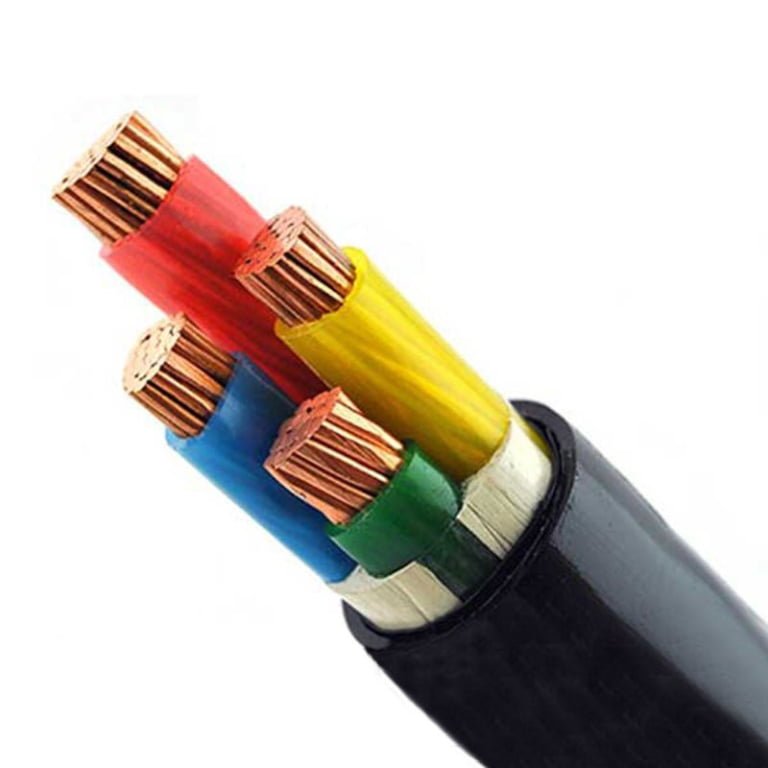
The four fundamental types of wiring are solid wire, stranded wire, flexible stranded wire, and extra-flexible wire — corresponding roughly to IEC 60228 Classes 1, 2, 5, and 6. Each type is defined by conductor construction, which determines its bend radius, fatigue resistance, current-carrying capacity, and the environments it can reliably serve. Choosing correctly depends on whether the installation is fixed, occasionally flexed, or in continuous motion.
What makes this more interesting than it might first appear is that the boundaries between types are blurry in practice — a Class 2 stranded conductor in a tight, vibrating cabinet behaves more like a problem than a solution, and a Class 5 flexible cable in a direct-burial trench is just money wasted on a property you’ll never use. The IEC 60228 framework covers roughly 95% of commercial wiring applications worldwide, yet misapplication remains one of the most common root causes of premature cable failure on the plant floor. Understanding what separates these four categories — and when each one earns its place in a design — is worth getting right the first time.
Type 1 — Solid-Conductor Wiring: Construction, Ratings, and Where It Belongs
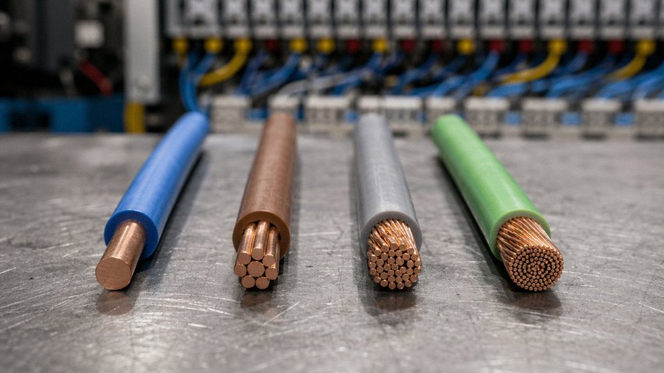
A solid conductor is exactly what it sounds like: a single drawn rod of copper or aluminum, no assembly of strands, no air gaps, no interstice geometry to worry about. That simplicity is both its greatest strength and the source of every failure mode you’ll encounter when someone specifies it wrong.
How Solid Conductors Are Made and What the Standards Say
Starting from an electrolytic copper rod (typically 8 mm diameter at the rod mill), the wire is drawn down through a series of dies until it reaches the target cross-section. For building wiring, that usually means somewhere between 0.5 mm² and 35 mm². Above that — 50 mm² through 630 mm² — you’re looking at utility feeders, busbars, and earthing risers where the rigid, monolithic geometry is actually an advantage for clamp-type connections.
IEC 60228 Class 1 governs solid conductors internationally. ASTM B3 covers solid annealed copper wire in North American specifications. Both set dimensional and resistance tolerances; they are not interchangeable on a line-by-line basis, so if you’re procuring for a project that mixes IEC-jurisdiction equipment with NEC-jurisdiction panels, check which standard the terminal manufacturer tested against. It matters more than people think.
Electrical and Physical Properties That Drive Specification
Because a solid conductor is a single homogeneous cross-section, it has no air gaps between strands. That gives it marginally lower DC resistance per unit length compared with an equivalent-area stranded conductor — the difference is small, usually 1–3%, but it compounds over long feeder runs and it’s why some utility engineers still prefer solid aluminum for distribution.
The rigidity, though, is the property you feel on the job site. Minimum bend radius for solid conductors is typically 8–10 times the conductor diameter, versus 4–6 times for Class 5 flexible stranded. Try to bend a 10 mm² solid copper conductor tighter than that and you’ll see the surface start to show micro-cracking. Do it repeatedly and you’ve initiated fatigue failure. The conductor won’t fail immediately — it’ll fail six months later, at a termination you can’t easily inspect.
Screw-type terminals, on the other hand, genuinely prefer solid wire. Stranded conductors relax under a screw terminal over time (strand relaxation is a real phenomenon, not a theoretical one), causing the clamping force to drop and resistance at the joint to creep upward. Solid conductors don’t do that. For fixed residential branch circuits, that termination stability is one of the main reasons NEC 14–10 AWG wiring is almost universally solid.
Where Solid Wire Belongs — and Where It Doesn’t
Primary applications: residential branch circuits (14, 12, and 10 AWG per NEC, rated 15 A, 20 A, and 30 A respectively at 60°C insulation), conduit runs in commercial buildings where the wire goes in once and never moves again, grounding electrode conductors, and direct-burial feeders where mechanical rigidity under soil loading is useful rather than a liability.
Do not specify solid conductor for flexible conduit sections, motor leads, or any termination point subject to vibration. Solid copper work-hardens with repeated flexing — this is a metallurgical fact, not a precaution to add to a spec sheet and ignore. NEC 300.14 requires a minimum 150 mm of free conductor at outlet boxes partly because bending solid wire flush against the back of a box, then re-bending it during device changes, is a documented failure pathway.
One operational warning worth stating plainly: in panels near rotating equipment, even what looks like a “fixed” conduit run can transmit enough vibration through the conduit wall to eventually crack a solid conductor at the terminal. If there’s any doubt, go stranded at those last 300 mm.
Material Options: Copper vs. Aluminum, Hard-Drawn vs. Annealed
| Material | Conductivity (% IACS) | Weight vs. copper | Relative cost index | Terminal requirement |
|---|---|---|---|---|
| Hard-drawn copper | ~97% | 1.0× | High | Standard screw terminal |
| Annealed copper | ~100% | 1.0× | High | Standard screw terminal |
| Solid aluminum | ~61% | ~0.3× | Low–medium | Anti-oxidant compound required |
Aluminum solid is cheaper and lighter — meaningfully so on long utility runs. But aluminum oxidizes at the terminal surface, and that oxide layer has much higher resistance than the base metal. Skip the anti-oxidant compound on an aluminum solid termination and you will eventually have a hot joint. This is not a theoretical concern; it’s the root cause behind a significant share of residential electrical fires in the 1960s–70s when aluminum branch-circuit wiring was common.
Annealed copper is the practical choice for most building wiring: softer than hard-drawn, easier to pull around bends in conduit, still fully compliant with IEC 60228 Class 1. Hard-drawn copper shows up in overhead span applications where tensile strength matters more than flexibility.
Solid conductors have lower DC resistance than equivalent cross-section stranded conductors due to the absence of inter-strand air gaps.True
The geometric fill factor of a stranded conductor means the effective conductive cross-section is slightly less than the nominal value; IEC 60228 and ASTM standards account for this in resistance specifications, and solid Class 1 conductors consistently show resistance values at or below the stranded Class 2 equivalent for the same nominal area.
Jinda’s solid copper conductors are drawn from electrolytic copper at ≥99.9% Cu purity, annealed in-line through a controlled atmosphere furnace to hit a defined softness range rather than just “annealed or not,” and diameter-verified at the exit die by laser micrometer to ±0.01 mm. For bulk international orders, that tolerance consistency means resistance values across a full drum shipment stay within a narrow band — which matters when you’re designing protection relay settings around worst-case loop impedance.
Type 2 — Stranded-Conductor Wiring: Flexibility Classes and Industrial Selection Logic
Stranded conductors are, at their core, a geometric solution to a mechanical problem. Instead of one solid cross-section, you have multiple smaller wires twisted helically — usually around a central wire or core strand — so the cable can bend without concentrating strain at a single point. The physics is straightforward: when a conductor bends, the outer fibers stretch and the inner ones compress. Distribute that load across dozens or hundreds of fine wires, and each individual wire sees only a fraction of the total stress. That’s the whole principle.
IEC 60228 formalizes this into a tiered classification system, and it’s worth knowing each tier well rather than defaulting to “stranded = flexible enough.”
IEC Class 2: Concentric-Stranded for Fixed Runs
Class 2 is the workhorse of industrial conduit and cable tray installations. Conductors are concentrically stranded — layers of wires wound in alternating directions around a center core — which gives stable, predictable geometry and consistent DC resistance across the cross-section. Strand counts and individual wire diameters are tightly defined; a 16 mm² Class 2 copper conductor, for instance, typically uses 7 wires of roughly 1.7 mm diameter. It’s not designed to flex in service. You route it, dress it, terminate it, and it stays put. Compared to Class 1 solid, it’s marginally easier to pull through conduit on long runs because it conforms slightly to bends during installation, but don’t mistake that for dynamic flexibility.
Class 5 and Class 6: Where Strand Count Really Matters
This is where selection logic gets more consequential. A 10 mm² Class 5 conductor can sustain more than 10,000 flex cycles at a 4× cable-diameter bend radius without failure. The equivalent solid conductor — or even a Class 2 — typically fractures within 20 to 50 cycles under the same conditions. That gap is not marginal. It’s the engineering basis for the entire IEC classification system.
A 10 mm² IEC Class 5 stranded conductor can sustain more than 10,000 flex cycles at a 4× diameter bend radius, while a solid conductor of equivalent cross-section typically fails within 20–50 cycles under the same conditions.True
IEC 60228 and industry flex-life testing consistently demonstrate this performance difference; it is the mechanical rationale behind the Class 5 designation for portable and repeatedly flexed equipment.
Class 5 achieves this through finer individual wire diameters and higher strand counts than Class 2 at the same nominal cross-section. It covers machine tool wiring, control panel internal wiring, welding cable leads, and portable power tools — anywhere the cable moves repeatedly but not continuously at high speed.
Class 6 goes further. Fine-wire construction, often bunch-stranded rather than concentrically laid, packs the maximum number of very fine wires (strand diameters down to 0.10 mm or finer) into the available cross-section. Bunch stranding sacrifices the geometric regularity of concentric construction in favor of flexibility per square millimeter. The tradeoff is a slightly larger outer diameter for a given conductor area, and current distribution across the cross-section is less uniform under AC conditions — worth factoring in at higher frequencies or in inverter-fed applications. Class 6 is specified for robotics umbilicals, drag-chain cables, winding drums, and offshore dynamic umbilicals where continuous motion is the operational baseline, not an exception.
Stranding Patterns and What They Actually Change
Concentric stranding keeps resistance predictable and outer diameter compact — good for fixed and semi-flexible applications. Bunch stranding maximizes flexibility but adds diameter. For very large cross-sections — think 185 mm² or 240 mm² flexible welding or shipboard cables — rope-lay construction is used, assembling the conductor from multiple stranded sub-cores twisted together. Rope-lay handles the geometry of large cross-sections while maintaining bend-ability, but it does increase the overall cable diameter noticeably, which matters when you’re routing through tight cable glands or calculating fill ratios in a drag chain.
Termination: The Step That Undoes Good Conductor Selection
Stranded conductors require more termination discipline than solid wire, and this is where installation teams sometimes cut corners. In spring-clamp or cage-clamp terminals — common in modern control panels — loose individual strands can escape the clamping zone, creating a high-resistance contact point that generates heat under load. The fix is EN 46228-compatible bootlace ferrules, crimped onto the stripped end before insertion. This is mandatory, not optional. For larger lugs, torque-controlled crimping matters: under-crimped lugs have higher interface resistance, and over-crimped ones can nick individual strands, reducing the effective cross-section.
Yes, ferrule installation adds time and cost per termination. In a cabinet with 300 terminals, that’s real labor. But a single overheated terminal block in a control panel — caused by strand scatter on a 2.5 mm² conductor — can take a production line down for half a shift and require partial cabinet rewiring. The math favors doing it right.
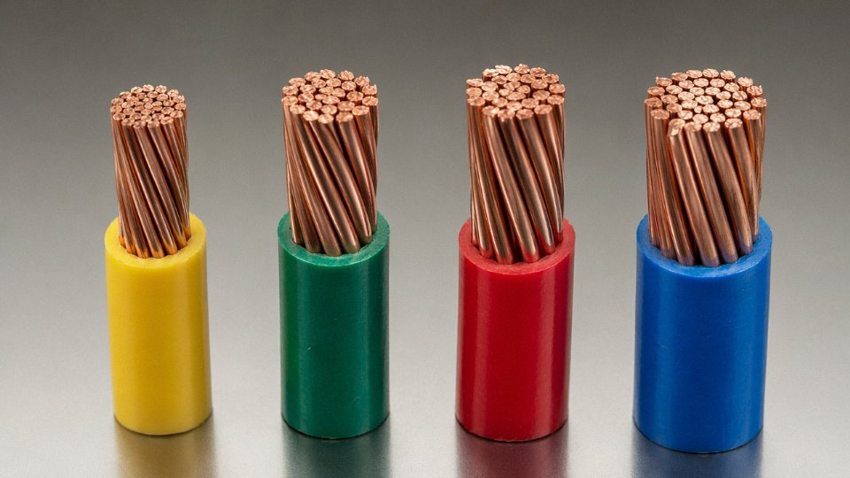
Jinda manufactures IEC Class 2 through Class 6 conductors in both bare copper and tinned copper — tinned being the sensible choice for marine, offshore, and high-humidity environments where oxidation at the strand surface would otherwise creep up and degrade contact resistance over years. Strand diameters go down to 0.10 mm for Class 6 fine-wire construction, with in-house strand-count verification and IEC 60228 resistance testing conducted before shipment. For procurement managers specifying flexible cables for drag-chain or robotics applications, the Class 6 option with tinned fine-wire construction is worth requesting as a standard line item rather than a special order.
Type 3 — Flexible and Specialty Wiring: Armored, Fire-Resistant, and High-Temperature Variants
Here’s where the category logic shifts. Types 1 and 2 are defined by what’s inside — solid or stranded copper or aluminum. Type 3 is defined by what surrounds the conductor: the jacket system, armor layer, insulation compound, or shielding arrangement. The core is almost always stranded (you need some flexibility to install and terminate these cables), but that’s incidental. The differentiating engineering is on the outside.
That distinction matters when you’re writing a project spec. Calling out “stranded conductor” tells a procurement team nothing useful about whether a cable will survive direct burial in clay soil, remain circuit-intact for 90 minutes during a building fire, or resist hydraulic fluid dripping from overhead machinery. You need to specify the outer system explicitly.
Armored Cables: SWA, AWA, and Interlocked Armor
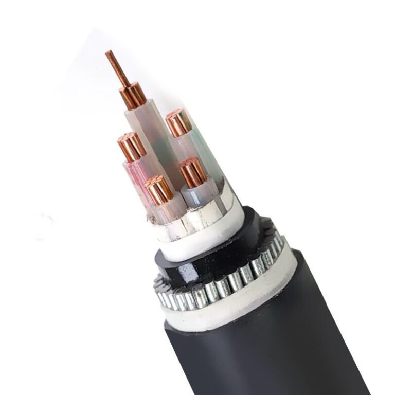
Steel wire armor (SWA), constructed to IEC 60502-1, is the workhorse for direct-burial power distribution and exposed industrial runs. The galvanized steel wires wound around the core provide crush resistance — typically enough to survive a loaded vehicle crossing a poorly protected trench, depending on soil type and backfill — and the armor is genuinely effective against rodent attack, which matters more than people admit in food processing plants and agricultural facilities. Burial depth still matters; armor is not a substitute for adequate cover.
Aluminum wire armor (AWA) deserves more attention than it usually gets on single-core medium-voltage cables. Steel armor on a single-core AC cable creates a shorted turn and induces circulating currents that measurably increase losses. Switching to AWA eliminates that magnetic effect and cuts overall cable weight by roughly 30–40%, which simplifies pulling and reduces support structure loads on cable trays.
Interlocked aluminum armor — Type MC cable under NEC Article 330 — takes a different approach. The interlocking profile allows the cable to flex and route around obstacles while still providing mechanical protection that rigid conduit would otherwise handle. In practice, this is the go-to solution for US commercial and industrial projects where you want to avoid pulling wire through EMT everywhere but still need crush and physical protection. Specify minimum armor coverage (typically 95% or better) and confirm the armor wire diameter in your procurement document; undersized armor wire on cheaper imports is a real issue.
Fire-Resistant and LSZH Cables
Four IEC standards address fundamentally different failure modes in fire scenarios, and confusing them is a costly mistake.
IEC 60331 tests circuit integrity — can the cable keep a circuit alive (say, powering emergency lighting or a fire pump) while burning? IEC 60332 tests flame propagation — will the cable spread a fire along its run? IEC 60754 measures the corrosiveness and acidity of gases emitted during combustion. IEC 61034 measures smoke density, which is what actually kills people trying to evacuate a tunnel or airport terminal.
A cable can pass 60331 and still emit dense toxic smoke. You often need compliance with all four, and the specification has to say so explicitly.
LSZH (Low Smoke Zero Halogen) jacketing is now mandatory in EU tunnels, airports, metro systems, and densely occupied buildings across much of Asia. The performance driver is evacuation time, not cable cost. A standard PVC jacket releases hydrogen chloride gas and thick black smoke when burning; LSZH compounds suppress both.
LSZH cables cost more than standard PVC-jacketed cables of the same conductor cross-sectionTrue
LSZH compounds use specialized polymer blends (typically EVA/ATH or similar) that are genuinely more expensive to compound and process than commodity PVC. Cost premium runs roughly 15–35% depending on conductor size and order volume.
Jinda compounds its LSZH material on-site rather than buying pre-compounded pellets from a third party. That matters for projects requiring third-party fire certification — batch-to-batch compound consistency is what certification bodies look at when auditing production. Off-the-shelf compound from varying suppliers introduces variability that can cause re-testing headaches mid-project.
High-Temperature Wiring: Silicone, PTFE, and Fiberglass
For wiring inside furnaces, motor internal leads, LED driver cavities, and process plant instrumentation, standard PVC or XLPE insulation simply ages out fast at elevated ambient temperatures.
Silicone rubber insulation handles continuous service at 180–200°C and remains flexible at low temperatures, which is useful in cold-climate outdoor installations. The aging characteristic is gradual surface crazing rather than sudden cracking, which gives some visual warning. The handling downside: silicone insulation is softer and more easily nicked during installation than thermoplastic insulations. Train your electricians accordingly, or you’ll find installation damage only when the motor fails six months later.
PTFE (commonly known by the DuPont brand name Teflon, though several manufacturers produce it) is rated to 260°C continuous and offers chemical resistance that silicone cannot match — concentrated acids, fuels, many solvents. It’s the standard choice for lab instrument wiring and aggressive process plant environments. PTFE insulation is stiffer and less forgiving in tight termination spaces, and the material cost is substantially higher than silicone, so use it where the chemistry genuinely demands it.
Chemical-Resistant and Oil-Resistant Sheaths
Neoprene (CR) jackets have a long track record in outdoor and oil-exposed environments. PUR (polyurethane) has largely displaced CR in drag-chain and mobile equipment applications because it combines good oil and fuel resistance with a flex life that neoprene can’t match under repeated tight-radius cycling. A drag-chain cable that fails in 18 months because someone spec’d standard PVC sheathing costs far more in unplanned downtime than the price difference would have. When writing procurement documents for PUR sheathed cables, reference IEC 60811 series test requirements for oil immersion and abrasion resistance — otherwise you’re leaving the quality definition to the supplier’s judgment.
Type 4 — Coaxial, Data, and Signal Wiring: Shielding Architecture and Transmission Performance
Signal wiring is its own engineering discipline, and conflating it with power wiring is one of the more expensive mistakes you can make on a project. The primary metric for a power conductor is current-carrying capacity — ampacity, governed by conductor cross-section, insulation temperature rating, and installation method. Signal wiring doesn’t care about any of that in the same way. Its performance lives or dies on characteristic impedance, attenuation per unit length, near-end crosstalk (NEXT), far-end crosstalk (FEXT), and shield transfer impedance. These parameters drive fundamentally different construction tolerances and quality-control requirements. You can’t inspect them with a clamp meter; you need a TDR, a network analyzer, or at minimum a category-certified field tester.
Coaxial Cable: Impedance Is Geometry
A coaxial cable is deceptively simple — center conductor, dielectric, outer conductor, jacket — but the impedance is locked in by geometry. Specifically, it’s set by the ratio of the dielectric’s outer diameter to the center conductor diameter, and by the dielectric constant of the insulating material. Change either dimension even slightly during extrusion and the impedance drifts. That’s why foam-PE dielectrics require tightly controlled foaming density, and why PTFE-insulated precision coax costs several times more than standard foam-PE types.
The three impedance values you’ll actually encounter: 50 Ω is standard for RF and most instrumentation applications; 75 Ω is universal in CATV, broadcast video, and SDI signal chains; 93 Ω appears in legacy thin-net Ethernet installations, mostly in older industrial facilities where nobody’s bothered to re-cable. When the installed cable’s impedance deviates from the system’s design impedance, signal reflections occur at every discontinuity. These reflections are quantified as voltage standing wave ratio (VSWR) — a VSWR of 1.0 is perfect, and anything above roughly 1.5:1 starts causing measurable signal degradation in high-frequency applications. In a video surveillance system running at relatively low frequencies this is forgiving; in an RF instrumentation loop running at 1 GHz or above, a bad connector crimp that creates a 2 Ω impedance bump will show up immediately on a network analyzer as a return-loss spike.
Twisted Pair and Category Ratings
Structured copper data cabling is tiered by bandwidth: Cat 5e reaches 100 MHz and handles Gigabit Ethernet reliably in runs up to 100 m; Cat 6 extends to 250 MHz; Cat 6A to 500 MHz and supports 10GBASE-T over the full 100 m channel; Cat 8 pushes to 2000 MHz, though it’s realistically a data-center, short-run product — don’t specify it for a 90 m horizontal run in a factory and expect it to behave like it does in a server room patch scenario. TIA-568 and ISO/IEC 11801 define the performance tiers; if you’re procuring for an international project, confirm which standard the testing lab is certifying against, because the channel models are not identical.
Shielding is where procurement decisions get contested. UTP is adequate for clean commercial environments with no significant EMI sources. The moment you put variable-frequency drives on the same cable tray — or even in the same building with inadequately routed cable paths — UTP starts picking up noise. In an automotive assembly plant or a paper mill with large VFDs, shielded twisted pair is essentially mandatory. FTP (overall foil shield) handles moderate environments. SFTP — individual foil shields per pair plus an overall braid — is the serious option for high-interference industrial LAN runs. The braid provides low transfer impedance at lower frequencies; the foil handles higher-frequency noise. In practice, the plants that skip shielding to save $0.08 per meter on cable end up spending far more troubleshooting intermittent network dropouts six months after commissioning.
Instrumentation and Fieldbus Cables
For 4–20 mA analog loops, thermocouple extension, and fieldbus wiring, individual pair shielding plus an overall shield (IS+OS construction) is the standard approach. Each pair carries its own Mylar or aluminum-polyester foil drain, and the whole assembly gets a collective braid or foil. This matters because a multi-pair cable in an instrument tray can have 24 or more pairs all running parallel — without individual shields, capacitive crosstalk between pairs corrupts low-level analog signals.
Fieldbus protocols add another layer of constraint. PROFIBUS DP specifies a characteristic impedance of 135–165 Ω with a capacitance below 30 pF/m and a specific AWG range for the conductor. Deviate from these parameters and the maximum segment length collapses, or you get reflections that look exactly like a loose termination resistor. FOUNDATION Fieldbus has similarly tight capacitance requirements. RS-485 Modbus is more tolerant but still benefits from matched-impedance cabling on runs above roughly 30–40 m. These are not suggestions buried in a network engineer’s handbook; they’re the reason why using generic multi-core control cable for fieldbus segments — because it was available in the storeroom — is a recurring cause of commissioning delays.
PROFIBUS DP cable requires a characteristic impedance of 135–165 Ω and capacitance below 30 pF/m to achieve rated segment lengths per IEC 61784 and the PROFIBUS specification.True
These parameters are defined in the PROFIBUS specification (IEC 61784-1) and Siemens/PI (PROFIBUS International) installation guidelines. Non-compliant cable reduces maximum segment length and causes reflections at high node counts.
Fiber Optic Wiring: A Parallel Track
Optical fiber deserves acknowledgment here even though it isn’t conductor-based wiring. Single-mode fiber is the right answer for distances beyond roughly 300–500 m and for backbone links where bandwidth headroom matters for the next decade. Multimode OM3/OM4 covers most in-building or inter-building runs up to 300–400 m at 10G. The real advantages over copper data cabling — complete EMI immunity and galvanic isolation — are compelling in any facility with heavy switchgear, arc furnaces, or cathodic protection systems. Cost per meter of fiber itself is lower than Cat 6A, but the transceivers and patch panels add up, especially in smaller installations. In practice, most industrial facilities end up with a hybrid architecture: fiber for the backbone and inter-panel runs, copper Cat 6A for the last 90 m to workstations and IP devices. Hybrid copper-fiber cables — which carry optical fibers and copper conductors in a single sheath — make sense for specific applications like IP camera installations where you need both data and power-over-wire to the same location.
Jinda’s data and instrumentation cable range includes screened multi-pair instrumentation cables in both IS+OS and overall-shield-only constructions, coaxial cables for CCTV and RF distribution, and multi-core control cables with controlled capacitance and conductor resistance to IEC 60189 and IEC 61156. Electrical test reports are issued per drum, which matters for project documentation on IEC-governed installations where the testing authority wants traceable conductor resistance and insulation resistance values — not just a batch certificate.
Side-by-Side Comparison: Selecting the Right Wiring Type Across 12 Common Application Scenarios
The table below is not a shortcut — it is a structured starting point. Use it to catch obvious mis-specifications early, then verify against the applicable standard for your jurisdiction.
| Application Scenario | Recommended Wiring Type | Key Standard | Critical Selection Parameter | Common Mis-specification Risk |
|---|---|---|---|---|
| Residential branch circuit | Solid conductor (IEC Class 1 / NEC 14–10 AWG) | NEC Article 310 / IEC 60228 | Ampacity at 60°C insulation rating | Using stranded where conduit fill and termination torque specs assume solid |
| Commercial conduit feeder | Stranded (IEC Class 2) | IEC 60502-1 / NEC THWN-2 | Voltage drop over run length | Under-sizing conductor cross-section to cut first cost |
| Industrial motor lead | Flexible stranded (IEC Class 5) | IEC 60227 / UL 508 | Motor starting current, termination compatibility | Specifying Class 2 where vibration causes strand fatigue at lugs |
| Robotics drag chain | Extra-flexible (IEC Class 6) | IEC 60228 Class 6 / UL Subject 2250 | Flex cycles (often 5–20 million), bend radius | Using Class 5 where Class 6 is required; premature conductor fracture within 6–18 months |
| Data center horizontal cabling | Data/signal (Cat 6A UTP or STP) | TIA-568-C.2 / ISO/IEC 11801 | Channel insertion loss, alien crosstalk | Running Cat 6A alongside high-current feeders without adequate separation |
| CCTV backbone | Coaxial (RG-59 or RG-6) | IEC 61196 / SCTE 74 | Impedance match (75 Ω), attenuation per 100 m | Substituting RG-59 for longer runs where RG-6’s lower attenuation is required |
| Oil platform power cable | Armored, mud/oil-resistant (IEC Class 5, SWA + SHF1 sheath) | IEC 60092-353 | Flame retardancy, hydrocarbon resistance | Specifying land-grade armored cable that lacks offshore mud-resistance sheathing |
| Underground MV distribution | MV XLPE (IEC 60502-2, 6–36 kV) | IEC 60502-2 / NEC MV-105 | Insulation wall thickness for rated voltage class | Ordering LV cable for a 6 kV circuit — insulation breaks down under surge; latent failure |
| Fire alarm circuit in tunnel | Fire-resistant (IEC 60331, E30/E60/E90 rated) | IEC 60331-21 / BS 6387 CWZ | Circuit integrity duration under flame | Using standard LSZH cable that is flame-retardant but not circuit-integrity-rated |
| Welding machine lead | Extra-flexible rubber (IEC Class 6, rubber insulated) | IEC 60245 / UL 62 Type SOOW | Current rating under intermittent duty cycle, abrasion resistance | Using PVC-insulated Class 5 — PVC stiffens and cracks under weld-area heat cycles |
| Thermocouple extension | Compensating/extension cable (thermocouple-grade alloy conductors) | IEC 60584-3 / ANSI MC96.1 | Alloy match to thermocouple type (K, J, T, etc.) | Using copper instrument cable — introduces an unknown junction EMF; reading errors of 5–15°C are common |
| Outdoor luminaire supply | UV-resistant flexible (IEC Class 5, UV-stabilized sheath) | IEC 60227-5 / NEC THWN-2 outdoor | UV degradation resistance, water ingress protection | Specifying indoor-grade flexible cord that chalks and cracks within 2–3 seasons |
Voltage Class as the Primary Filter
Before you even reach the four-type question, voltage class eliminates candidates. The hierarchy runs ELV (≤50 V AC) → LV (50–1000 V AC) → MV (1–36 kV) → HV (>36 kV), and insulation wall thickness scales sharply at each step — an IEC 60502-2 6 kV cable carries roughly 3–4 mm of XLPE insulation where a comparable 1 kV cable carries under 1 mm. The four wiring types still exist at every voltage class; a solid conductor can be a solid MV cable, and shielded signal cables appear in ELV instrumentation loops. What changes is the test voltage requirement and the conductor screen/insulation screen construction mandatory above LV. The failure mode that catches contractors most often is selecting the correct type but the wrong voltage rating. That cable will pass installation inspection, run normally under steady-state load, and then fail silently during the first switching transient or lightning surge. By the time the fault appears, the cable is in conduit or buried.
Using a low-voltage rated cable on a medium-voltage circuit creates a latent dielectric failure that may not manifest until a transient overvoltage event, potentially years after installation.True
Dielectric breakdown voltage is a function of insulation wall thickness and material dielectric strength. An under-rated cable operates below its breakdown threshold under normal voltage but can fail when transient overvoltages — switching surges, lightning — temporarily exceed that threshold. IEC 60502-2 mandates specific insulation thicknesses and high-voltage AC test requirements precisely to provide this margin.
Environmental Duty Cycle Scoring
A fast way to narrow subtype selection is to score your application on three axes, each rated 1–5.
Mechanical flex duty: 1 = permanently fixed in conduit, never moved after installation; 3 = occasional repositioning during maintenance; 5 = continuous motion, drag chain or cable tray with daily flex cycles in the millions.
Chemical and thermal severity: 1 = dry, climate-controlled indoor space; 3 = outdoor UV and moisture exposure or moderate heat (up to roughly 90°C); 5 = chemical plant with solvent splash, offshore hydrocarbon atmosphere, or furnace adjacency above 150°C.
EMI and signal integrity criticality: 1 = power-only circuit where noise is irrelevant; 3 = standard fieldbus or building automation; 5 = precision analog instrumentation, thermocouple loops, or high-frequency data transmission where a few millivolts of induced noise corrupts the reading.
Plot your three scores and the wiring type narrows quickly. A score of (1, 1, 1) lands you in solid or standard stranded conductor — Class 1 or Class 2, nothing exotic. A score of (5, 3, 1) is drag-chain robotics: IEC Class 6, TPE or PUR jacket, no shielding needed. A score of (1, 2, 5) is a thermocouple extension in a relatively benign environment: alloy-matched compensating cable, foil shield, low-noise. A score of (5, 5, 4) — continuous-flex, high-heat, signal-critical — is genuinely difficult and usually requires a specialty manufacturer to engineer a hybrid construction. In my experience, most specifiers land in the middle range and try to solve it with whatever they used on the last project, which is exactly where mis-specification accumulates.
Cross-Standard Translation for International Projects
Procurement teams buying for projects that must satisfy both IEC and NEC/UL simultaneously need a direct pairing. The standards use different nomenclature for essentially the same constructions, and customs documentation often requires both references.
| IEC Designation | Closest NEC / UL Equivalent |
|---|---|
| IEC 60228 Class 1 solid | NEC Article 310, solid THHN/THWN |
| IEC 60228 Class 2 stranded | NEC Article 310, stranded THHN/THWN |
| IEC 60228 Class 5 flexible | UL 66 flexible cord, Type SO / SOOW |
| IEC 60228 Class 6 extra-flexible | UL Subject 2250 continuous-flex cable |
| IEC 60502-1 SWA armored LV | NEC Type MC armored cable |
| IEC 60502-2 MV XLPE | NEC Type MV-105 |
| IEC 60331 fire-resistant | UL 2196 circuit-integrity cable |
| IEC 61196 coaxial | UL 444 communications cable |
These pairings are close equivalents, not exact substitutes. Test voltage levels and marking requirements differ, and some jurisdictions require both designations to appear on the cable surface. When in doubt, get written confirmation from the cable manufacturer that the specific construction meets both standards — not just one.
Total Cost of Ownership: Why Cheap Wire Is Rarely Cheap
The instinct to specify the minimum conductor size that clears ampacity tables is understandable. It is also usually wrong when you run the numbers over a 20-year asset life.
The physics is straightforward. Resistive losses scale with 1/A (cross-sectional area), so a 10% reduction in conductor area increases I²R losses by roughly 11%. That extra heat raises operating temperature, and every 10°C rise in conductor temperature roughly halves insulation service life — the Arrhenius relationship, well-established in IEC 60216 accelerated aging methodology. A cable running 10°C hotter than necessary ages twice as fast. On a 20-year design life, that means a replacement cycle at 10–12 years instead of 20.
The energy cost side is often more persuasive to plant owners. Consider a 10 mm² copper feeder running at 60–70% of rated load for 6,000–7,000 hours per year — a typical industrial production facility. Upsizing to 16 mm² reduces resistive losses by roughly 35–40%. At industrial electricity rates (which vary widely but commonly fall in the range of USD 0.06–0.14 per kWh in major manufacturing regions), that loss reduction on a feeder carrying 60–80 A can represent USD 400–900 per year in saved energy. The incremental material cost difference between 10 mm² and 16 mm² copper cable is usually recovered within 4–6 years, depending on copper prices at the time of procurement and local energy costs. The remaining 14–16 years of the asset life is pure gain, plus the avoided cost of an early replacement.
The table above is a starting filter. Combine it with the voltage-class hierarchy, the three-axis duty cycle score, and a basic present-value energy calculation, and most specification decisions become defensible before anyone runs a formal engineering calculation.
Installation Standards, Conduit Fill Rules, and Derating Factors That Govern All 4 Types
Choosing the right wire type is only half the job. Get the installation wrong and you’ve negated every careful specification decision made upstream — thermally overloaded conductors, signal corruption from poor segregation, or insulation cracking from a bending radius violation that won’t show up until six months of thermal cycling have done their damage.
Conduit Fill: The Thermal Logic Behind the Numbers
NEC Chapter 9, Table 1 sets fill limits that most people memorize without understanding why they exist. One conductor in a conduit: 53% fill. Two conductors: 31%. Three or more: 40%. IEC 61386 follows a similar philosophy. The reasoning is purely thermal — a conductor generates heat proportional to I²R losses, and that heat has to travel outward through the insulation, across any air gap, through adjacent cables, and finally through the conduit wall to ambient. Pack the conduit tighter and you’ve lengthened that thermal path.
A worked example makes this concrete. Suppose you’re pulling three 10 AWG THHN conductors (each roughly 35 mm² cross-section, outer diameter approximately 5.2 mm) plus one 12 AWG equipment ground (outer diameter roughly 4.6 mm) into a single conduit. The combined cross-sectional area of those four conductors is about 143 mm². Divide by 0.40 (the three-or-more fill limit) and you need a conduit with at least 358 mm² internal area. A 1-inch EMT has roughly 353 mm² — too tight by a narrow margin. Step up to 1¼-inch EMT and you’re comfortably within limits. In practice, most experienced wiremen size up one step anyway to allow for future pulls.
Bundling Derating: Where Feeder Sizing Goes Wrong
IEC 60364-5-52 Table B.52.17 and NEC Table 310.15(C)(1) both apply grouping factors to bundled conductors sharing a common thermal environment. The factors are straightforward: 4–6 current-carrying conductors together draw a 0.80 multiplier; 7–9 conductors, 0.70; 10–12, 0.65. What’s easy to miss is that these factors stack with temperature correction.
Take a 6 mm² copper conductor rated 41 A in free air at 30°C ambient. Bundle it with five other loaded cables and the 0.80 factor drops the allowable current to 32.8 A. If that same tray is routed through a boiler room sitting at 45°C, you’re applying an additional ambient correction on top of that. The conductor that looked adequately sized on a one-line diagram is now undersized for actual operating conditions. This is a recurring source of nuisance tripping — and occasionally worse — in industrial feeder design.
Ambient Temperature Correction Is Not Optional
NEC ampacity tables reference 30°C ambient. IEC tables use either 30°C or 40°C depending on the installation method. A 60°C-rated insulation system (common in older or cost-driven installations) takes a 0.82 correction factor at 40°C ambient; a 75°C-rated system takes 0.91. Roof-mounted conduits in summer, enclosures near process heat, cable trays above ovens — these environments routinely run 15–20°C above the reference temperature, and ignoring correction here is how you get conductors running at 90–95% of thermal limit continuously.
Minimum Bending Radius by Wire Type
This one causes subtle long-term failures. Solid conductors require a minimum bending radius of 8–10× overall diameter; standard Class 2 stranded, 6–8×; flexible Class 5/6 in dynamic service, 4–6×; coaxial and structured data cables, 8–10× to prevent dielectric deformation that shifts impedance. A post-installation continuity test won’t catch a kinked coax — but attenuation measurements will, and intermittent signal faults under thermal cycling will find it eventually.
Segregation of Signal and Power Wiring
IEC 60364-5-52 and EN 50174 both require physical separation between power and signal cables. For unshielded parallel runs, 100 mm minimum separation is the standard starting point; a metallic separator in the same tray can reduce that to around 50 mm. Where cables cross, right-angle crossing drops inductive coupling by roughly a factor of 10 compared to a parallel run — a simple routing discipline that costs nothing at installation and prevents significant instrumentation noise problems later.
Jinda's application engineering team provides conduit fill calculations, derating worksheets, and installation drawings as part of pre-sales technical support.True
This is a stated service offering from Shandong Jinda Special Cable Group, enabling contractors and EPCs to produce accurate bill-of-materials documentation before project commitment.
Jinda’s application engineering team works through conduit fill calculations, derating factor worksheets, and installation drawings during the pre-sales phase — the kind of documentation that EPCs and project owners need before a bill of materials can be finalized. For projects with non-standard ambient conditions or dense cable trays, that support typically saves one or two rounds of redesign after the fact.
How to Write a Procurement Specification That Ensures You Receive the Right Wiring Type
A technically sound cable choice means nothing if the specification document that goes to your supplier is vague. Procurement teams on large EPC projects get burned not because engineers specified the wrong cable type, but because the purchase order language left enough room for a supplier to ship something cheaper and technically “compliant” — at least on paper. Closing that gap requires deliberate specification writing.
The Seven Clauses Every Cable Specification Must Contain
Start with conductor class and material. State IEC 60228 Class explicitly — Class 1, 2, 5, or 6 — and specify whether the conductor is plain annealed copper, tinned copper, or aluminum. “Copper conductor” alone is not enough; a supplier can ship Class 1 solid where you needed Class 5 flexible and be technically correct.
Insulation material and rated voltage comes next. PVC, XLPE, EPR — each has a different thermal ceiling and chemical resistance profile. State the rated voltage in the Uo/U format (e.g., 0.6/1 kV) and the insulation standard edition year. Standards get revised; an old edition may permit thinner insulation walls that newer editions have tightened.
Armor and shielding type, where applicable: specify construction explicitly — SWA (steel wire armor), DSTA (double steel tape armor), copper braid with minimum 85% optical coverage, foil-plus-drain wire. Percentage coverage matters enormously for EMI performance on instrumentation cables.
Outer sheath material and color coding must be called out by compound designation (PVC Type ST2, LSZH Category Cf per IEC 60332) and, where applicable, standard color (orange for medium-voltage, black for general industrial). Color substitutions sound trivial until a maintenance electrician misidentifies a circuit.
The applicable standard and edition year anchors everything. Specify “IEC 60502-1:2004+AMD1:2009” rather than “IEC 60502-1.” One project I’m aware of had a dispute resolved entirely on which amendment applied — the supplier had tested to the base edition.
Test certificates required: at minimum, type test reports (conductor resistance, insulation resistance, HV test, flame test where relevant), routine test certificates per drum, and a factory drum test report. Routine tests are performed on every drum; type tests confirm the design. Both matter.
Finally, marking requirements: outer sheath must show manufacturer name, cable type designation, voltage rating, applicable standard number, and sequential meterage marking — typically every meter or every two meters. Conductor identification (color coding or numbered cores) must match the stated standard. Unmarked or incorrectly marked drums are grounds for rejection on arrival.
Substitution Clauses: Where Specifications Usually Break Down
The phrase “or equivalent” is where specifications fall apart. Open substitution language invites cross-section reductions, thinner insulation walls, and lower-grade sheath compounds that still nominally satisfy the specification category. Replace it with something like: “Substitutions must demonstrate compliance with IEC [number] confirmed by an accredited third-party test report not older than three years and must not reduce conductor cross-section, insulation wall thickness, or shield coverage below the specified minimums.” This kind of language has protected large EPC contractors from receiving conductors running 15–20% under nominal cross-section — a reduction that directly increases resistance, heating, and voltage drop under load.
Drum Traceability and Receiving Inspection
Each drum should carry: manufacturer name, cable type, conductor cross-section, drum length, gross and net weight, drum serial number, and manufacturing date. For hazardous area cables, IEC 60079-0 project requirements typically mandate drum-level test reports covering DC resistance per IEC 60228, insulation resistance, and voltage withstand. Specify these as a receiving inspection baseline — not a nice-to-have. A drum that arrives without traceable test data is, operationally, an unknown quantity.
Factory Acceptance Testing for Large Orders
For orders typically above USD 500,000 or roughly 50 km of cable, a witnessed FAT protocol is worth the travel cost. The protocol should include dimensional checks per IEC 60811 (insulation and sheath thickness measurements — not just pass/fail, but recorded values), conductor resistance per IEC 60228, and high-voltage test per IEC 60502-1. Agencies such as SGS, Bureau Veritas, TÜV Rheinland, and Intertek conduct witnessed FATs at cable factories regularly; Jinda works with all four.
Jinda Cable provides drum-by-drum test reports uploaded to a project portal for international EPC orders.True
This is stated as a service offering within the manufacturer's described capabilities and procurement support model, consistent with practices at major cable manufacturers serving EPC contractors.
Lead Times and Phased Purchasing
Standard LV cable lead times run roughly 4–8 weeks from order confirmation, depending on conductor size, quantity, and sheath compound availability. Fire-rated or medium-voltage specialty cables typically require 16–24 weeks — sometimes longer if a specific armoring material is constrained. Align cable delivery with the project critical path by issuing phased purchase orders: bulk standard cable early, specialty types as design is confirmed. Jinda’s five production bases across China allow parallel production runs across cable types, which can meaningfully compress lead times on large mixed-type orders where a single factory would be the bottleneck.
Jinda also provides standard cable specification templates aligned to IEC, UL, and BS standards, along with pre-approved vendor list documentation packages formatted for EPC contractor AVL submissions — which cuts weeks off the supplier qualification process on time-sensitive projects.
Frequently Asked Questions About the 4 Types of Wiring
What is the most common type of wiring used in homes?
In North America, the answer is almost always solid-conductor NM-B cable — what most electricians still call “Romex” — running 14 AWG on 15 A branch circuits and 12 AWG on 20 A kitchen and bathroom circuits. The sheath is PVC, the conductors are solid copper, and the whole thing gets stapled to studs or pulled through bored holes. Simple, cheap, and it works well for circuits that go in once and never move again.
Europe and most of Asia use a different physical form — PVC-insulated solid or Class 2 stranded conductors pulled through conduit, or flat twin-and-earth cables in plaster chases — but the underlying logic is identical: residential fixed wiring uses solid or low-flexibility stranded conductors because nobody is bending that cable after commissioning. The flexibility classes engineered for drag chains and robot arms are genuinely wasted cost in a bedroom lighting circuit.
Can I use stranded wire instead of solid wire?
For current-carrying capacity, yes — a stranded conductor meets or exceeds the ampacity of a solid conductor at the same cross-sectional area, and in many jurisdictions it’s perfectly code-legal to substitute. The practical problem shows up at terminations. Many standard receptacles and switch terminals — particularly the push-in “back-stab” style common in residential work — are designed and tested for solid wire only. Use stranded in those and you get a marginal connection that loosens under thermal cycling.
The fix is ferrules on ring or fork lugs, which is standard industrial practice anyway. NEC 230.23 also requires solid copper conductors for certain service entrance configurations, so verify before you swap.
What does “flexible wiring” actually mean?
It is not just “stranded wire that bends easily.” IEC Class 5 and Class 6 conductors use individual strand diameters typically below 0.5 mm — sometimes well below — with far more strands per cross-section than Class 2. That construction distributes bending stress across hundreds of tiny strands instead of a few thick ones, which is what allows the cable to survive millions of flex cycles in a drag chain or a robot arm without fatigue cracking.
Class 2 stranded wire is pliable enough to route around obstacles during installation, but it is not designed for repeated dynamic bending. Run it in a cable track and you will start seeing broken strands within months, depending on bend radius and cycle rate. The distinction matters operationally, not just on paper.
Is coaxial cable a type of power wiring?
No. Coaxial cable is engineered around impedance control and signal loss minimization — the center conductor diameter, dielectric constant, and outer conductor geometry are all calculated to maintain 50 Ω or 75 Ω characteristic impedance, not to carry load current. The center conductor in a typical RG-6 or RG-58 cable is roughly 1 mm² or less. Using it for power circuits would violate NEC Article 800 and IEC 60364 application rules, and the conductor would overheat under any real load well before a breaker responded.
How do I identify wire approved for outdoor or underground use?
Read the cable marking printed on the jacket. For direct burial in North America, the marking will explicitly state “Direct Burial” or “DB.” IEC 60502-1 cables approved for underground installation method D will carry the appropriate designation on the drum label and documentation. Outdoor exposed runs need UV-resistant jacket material — HDPE, XLPE, or UV-stabilized PVC; standard gray PVC degrades within a few years of UV exposure and goes brittle in cold weather, which is a recurring problem on rooftop runs. For underground work near any future excavation activity, armored SWA construction adds meaningful protection that a jacket alone cannot provide.
What is the difference between a wire and a cable — and does it matter in specs?
In strict engineering usage, a wire is a single conductor; a cable is an assembly of two or more insulated conductors under a common outer sheath. This matters enormously when writing purchase orders. A spec that reads “2.5 mm² wire” is technically asking for a single conductor, and a supplier who ships single conductors is not wrong. Write “3-core 2.5 mm² cable to IEC 60502-1” and the deliverable is unambiguous. Procurement disputes over this are more common than they should be.
Why do some cables have both a foil shield and a braid shield?
Because they operate at different frequencies and serve different mechanical roles. Aluminum-polyester foil provides close to 100% optical coverage and performs well against high-frequency electric field interference above roughly 1 MHz. Braid typically covers 85–98% of the surface but has substantially lower transfer impedance at lower frequencies and tolerates repeated flexing far better than foil, which can crack at fold points. The combined construction — often marked SFTP or “double-shielded” — is what you reach for when the cable runs near variable-frequency drives, which generate interference across a wide spectrum from low-order harmonics up into the radio-frequency range. In those environments, foil-only cables on industrial Ethernet links produce intermittent communication errors that are genuinely difficult to diagnose until someone checks the shield type.
How does Jinda ensure consistent quality across bulk international orders?
Jinda operates an ISO 9001-certified quality management system across all five production bases, with manufacturing steps documented and traceable to raw material batch — conductor rod, insulation compound, and sheathing material all carry batch records. Every finished drum goes through routine electrical testing covering conductor resistance, insulation resistance, and voltage withstand before it leaves the line, and results are recorded on drum-specific test certificates that ship with the order.
Jinda coordinates third-party inspection by SGS or Bureau Veritas for large export ordersTrue
Third-party inspection by internationally recognized agencies is standard practice for major cable manufacturers supplying international project orders, and Jinda's documented export process includes coordination with customer-nominated inspection agencies along with full documentation packages — material certifications, test reports, and packing lists — for project handover and customs clearance.
For large export orders, third-party inspection through SGS, Bureau Veritas, or a customer-nominated agency can be coordinated, with complete documentation packages — material certifications, test reports, packing lists — provided for customs clearance and project handover records. On long-lead international orders, having that paperwork organized before the drums load onto a vessel prevents delays that can push commissioning schedules by weeks.
Jinda’s Global Supply Capability: Supporting International Projects Across All 4 Wiring Types
If you’ve worked through the technical content in this article — conductor classes, ampacity derating, shielding architectures, fire-survival ratings — you’re now in a position to write a cable schedule that actually reflects what the project needs. The harder problem, in most international projects, is finding a manufacturer who can execute against that schedule without forcing you to split orders across three or four vendors, each with different lead times, different submittal formats, and different ideas about what “compliant” means.
Manufacturing Scale That Covers the Full Cable Schedule
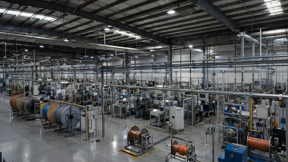
Jinda operates five production bases across Shandong Province, China, totaling roughly 470,000 m² of manufacturing floor space. That figure matters less as a marketing number and more as a practical signal: a plant of that scale can simultaneously run LV building wire extrusion lines, armored cable stranding, LSZH compound processing, and instrumentation cable assembly without one product line starving capacity from another. The product range maps directly onto the four wiring types covered in this article — solid and stranded low-voltage building wire, flexible industrial cables from IEC Class 2 through Class 6, armored and fire-resistant constructions, and shielded instrumentation and data cables. For a procurement manager assembling a cable schedule for a hospital build or a solar substation, single-source supply is not just a convenience; it eliminates the version-control risk that appears when multiple suppliers deliver to slightly different interpretations of the same specification.
Certifications That Hold Up Under Vendor Qualification Scrutiny
Jinda maintains active certification files covering IEC compliance with CE marking, UL Listed conductors for North American and export-specification projects, KEMA/DEKRA type-test reports for fire-rated cables, RoHS compliance documentation for LSZH cables entering EU markets, and CCC certification for China domestic supply.
Jinda holds active KEMA/DEKRA type-test reports for fire-rated cable constructions and can provide these as part of vendor qualification documentation.True
KEMA and DEKRA are accredited third-party test bodies whose reports are widely accepted by international specifiers and project certifiers; a manufacturer holding these reports has subjected specific cable constructions to standardized fire-survival testing rather than relying on self-declaration.
In project procurement, an “active” certification file means the test reports haven’t expired and the production standard hasn’t drifted from the tested construction — something worth verifying explicitly in your vendor qualification checklist. Jinda can supply compliance matrices and data sheets as part of the standard technical submittal package.
Export Experience Across Sectors With Distinct Specification Cultures
Fifty-plus countries of export history isn’t uniformly distributed. The sectors where Jinda has built the deepest reference base include infrastructure (airports, rail, highway tunnels), energy (solar farms, wind projects, distribution substations), industrial (petrochemical, automotive assembly, food processing), commercial construction (high-rise towers, data centers, hospitals), marine and offshore, and utility distribution. Each of those sectors carries its own cable specification culture — an offshore project engineer and a data center M&E consultant are asking fundamentally different questions about the same reel of armored cable. Jinda’s export sales team is trained to navigate those differences rather than defaulting to a single product sheet.
The Pre-Sales Workflow That Actually Shortens Your Procurement Cycle
The practical workflow runs like this: you submit a project cable schedule, a Jinda application engineer maps each line item to a standard product or configures a custom construction where needed, and a technical submittal package — data sheets, compliance matrices, samples if the project warrants them — comes back within roughly five business days. A formal quotation with a production and delivery schedule follows. That structured sequence compresses the RFQ-to-order cycle that quietly delays project procurement on almost every large installation.
Long-Term Traceability and Post-Delivery Support
Production records and raw material traceability are maintained for a minimum of ten years. For facility managers and insurance adjusters, that means warranty investigations and as-built documentation remain accessible well into the building’s operational life — not a trivial thing when a fire-rated cable question surfaces during a building insurance review eight years after installation. Replacement cable to match original specifications can be manufactured if project scope changes require additional quantities, which happens more often than any project schedule anticipates.
If you’ve worked through this article and have a cable schedule in hand, Jinda’s international sales team is the logical next contact. The goal is straightforward: one technical and commercial partner from specification development through final delivery, backed by 35-plus years of manufacturing depth and the standards knowledge to support it.