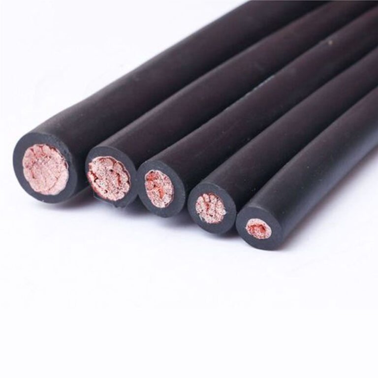
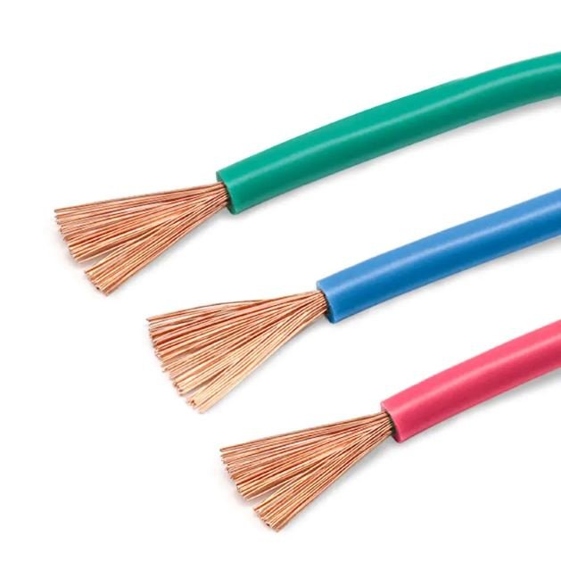
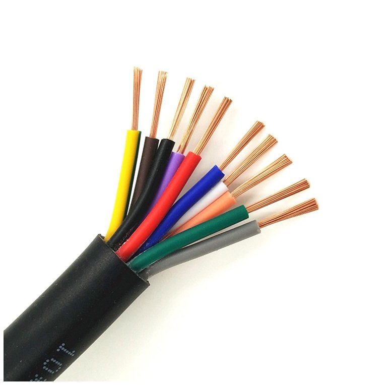
Pick the wrong cable for a control circuit and the failure rarely announces itself cleanly. You get intermittent faults — a sensor that drops signal under vibration, a PLC input that reads erratic during a cold startup, a solenoid valve that chatter-trips a line because the cable’s current-carrying capacity was margined too tight. Maintenance chases ghosts for shifts. Meanwhile the line sits or runs at reduced rate, and depending on what you’re making, an unplanned hour of downtime can cost anywhere from a few hundred to tens of thousands of dollars. The cable itself is almost never the most expensive component in a panel or a conduit run, but it is often the one that causes the most disproportionate damage when it’s specified wrong.
Control cables are used wherever a low-to-medium voltage signal or command must travel reliably between a control device and the equipment it operates — covering applications from factory automation, machine tool wiring, and conveyor systems to power plant instrumentation, building management, and process industry field wiring. Conductor cross-sections typically run 0.5 mm² to 10 mm², with core counts anywhere from 2 to 61 depending on how many discrete signals or actuator circuits the run must carry.
What makes the question genuinely interesting is how much “control cable” varies in practice. A 4-core screened cable pulling 4–20 mA signals in a chemical plant lives in a completely different world than a flexible 25-core cable flexing through a cable track on a robotic welding cell, even though both get called “control cable” on a bill of materials. The operating environment, the duty cycle, the signal type, and whether the cable ever needs to move — all of it changes the spec. The sections below walk through where these cables actually show up and what distinguishes a good installation from one that comes back to haunt you.
Control Cables in Manufacturing and Factory Automation — The Backbone of the Production Floor
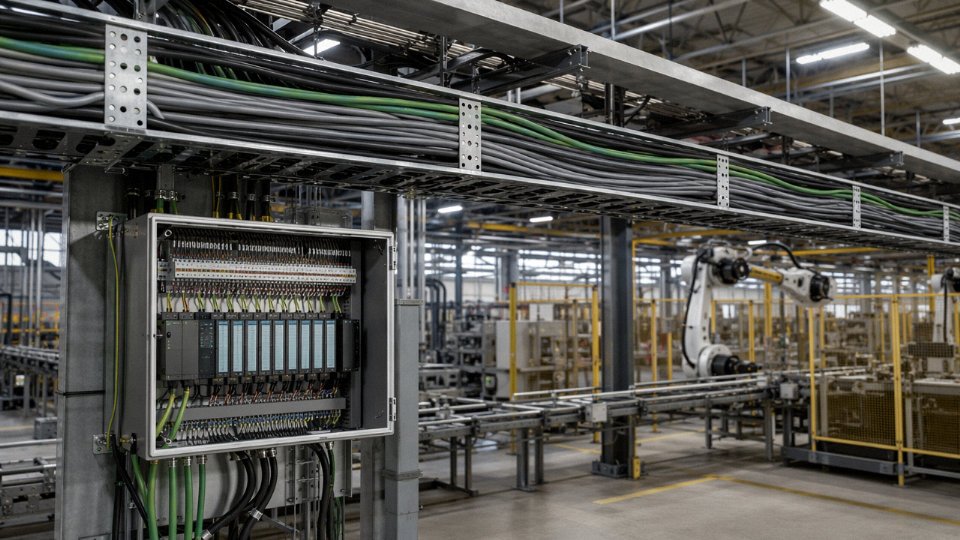
Walk through any working assembly plant and you’ll find control cables everywhere — bundled in cable trays overhead, threaded through conduit inside machine frames, looping through energy chains on robot arms. They’re unglamorous, often overlooked during commissioning, and absolutely critical. When one fails, the line stops.
How Control Cables Tie the Automation System Together
The core job is signal and low-power command transmission between the control layer and the field devices. In a typical discrete manufacturing cell, a PLC rack might send and receive signals to dozens of endpoints: motor starters in the MCC, pneumatic solenoid valves on an assembly fixture, inductive proximity sensors on a conveyor indexer, reed switches on pneumatic cylinders, and indicator lights on an HMI panel. Each of those connections is a control cable run. Core counts range widely — a two-core cable might serve a single limit switch, while a 19- or 37-core cable consolidates signals from an entire station back to the panel, reducing the total number of conduit entries. Cross-sections are typically 0.75 mm² to 2.5 mm² for most factory I/O work, though motor starter pilots and contactor coil feeds sometimes push to 4 mm².
The routing path matters more than most engineers appreciate during the design phase. A typical run starts inside a grounded steel enclosure, exits through a cable gland or conduit fitting, travels along a cable tray (usually perforated steel or wire mesh) through the facility, then drops into flexible conduit or a drag chain as it approaches the machine. Each transition point is a vulnerability — abrasion at conduit edges, crush loads where trays are overcrowded, water pooling in low spots. Specifying the right outer jacket hardness and minimum bend radius for each segment isn’t over-engineering; it’s preventing a $15 cable from causing $15,000 in downtime.
The EMI Problem Is Real and Routinely Underestimated
Factories are electrically noisy environments. Variable-frequency drives are probably the worst offenders — they generate broadband conducted and radiated interference that can easily corrupt 24 V DC control signals over unshielded cables routed nearby. Resistance welders, large contactors switching inductive loads, and high-current servo drives compound the problem. In practice, any control cable running more than a meter or two in a cabinet or tray that also carries power wiring should be shielded. A foil-and-drain construction is the minimum; braided shields are worth the cost on longer runs or in particularly dirty environments like robotic welding cells.
Unshielded control cables in close proximity to VFD output conductors can pick up enough induced noise to cause false triggering of PLC inputs, leading to intermittent faults that are genuinely difficult to diagnose.True
VFD switching frequencies (typically 2–16 kHz carrier) induce capacitive and inductive coupling onto adjacent unshielded conductors. The induced voltages can exceed the noise immunity thresholds of standard 24 V DC sourcing inputs, particularly at longer cable lengths or with high-impedance sensor circuits.
The drain wire needs to be grounded at one end only — typically the panel end — to avoid creating a ground loop. This is one of those installation details that gets skipped under schedule pressure and causes problems six months later.
Flex Life in Moving Applications
Standard fixed-installation control cables will crack and fail relatively quickly inside an energy chain or on a robot’s third axis. The conductors work-harden under repeated bending, the insulation develops micro-cracks, and you get intermittent continuity faults that are maddening to trace. Cables rated for continuous flexing use finely stranded copper conductors — often 0.1 mm or finer individual strands — with TPE or PUR jacket compounds that stay pliable without cracking. They’re rated for millions of flex cycles rather than thousands. The cost premium over standard cable is real but small relative to the labor cost of re-pulling a drag chain.
Temperature and Chemical Exposure on the Production Floor
Ambient conditions vary enormously across manufacturing environments. A light assembly area might never exceed 35°C and stay clean. A foundry floor, a glass tempering line, or the area directly above an induction furnace is a different world entirely. Cables in those zones need to be rated for continuous service at 90°C or higher — silicone rubber insulation handles up to around 180°C for extreme cases, while XLPE-insulated cables typically cover the 90–105°C range that most industrial hot-zone applications require.
Chemical exposure is equally important and easier to overlook during spec. Cutting fluid mist in machining centers, hydraulic oil splash near press lines, and cleaning solvents used during shift changeovers all attack PVC jackets over time, causing the material to soften, crack, or swell. An oil-resistant PUR or chlorinated polyethylene jacket adds maybe 10–20% to cable cost and can easily triple service life in those environments. The calculation isn’t complicated.
Control Cables in Power Generation and Electrical Substations — High-Stakes Signal Management
Power infrastructure is where control cable failures stop being a maintenance inconvenience and start being a safety event. A snapped conveyor sensor cable in a factory means a line stops. A failed trip signal cable in a 400 kV substation means a breaker doesn’t open when a fault occurs — and the consequences cascade fast.
Tripping Signals, Relay Outputs, and SCADA Links
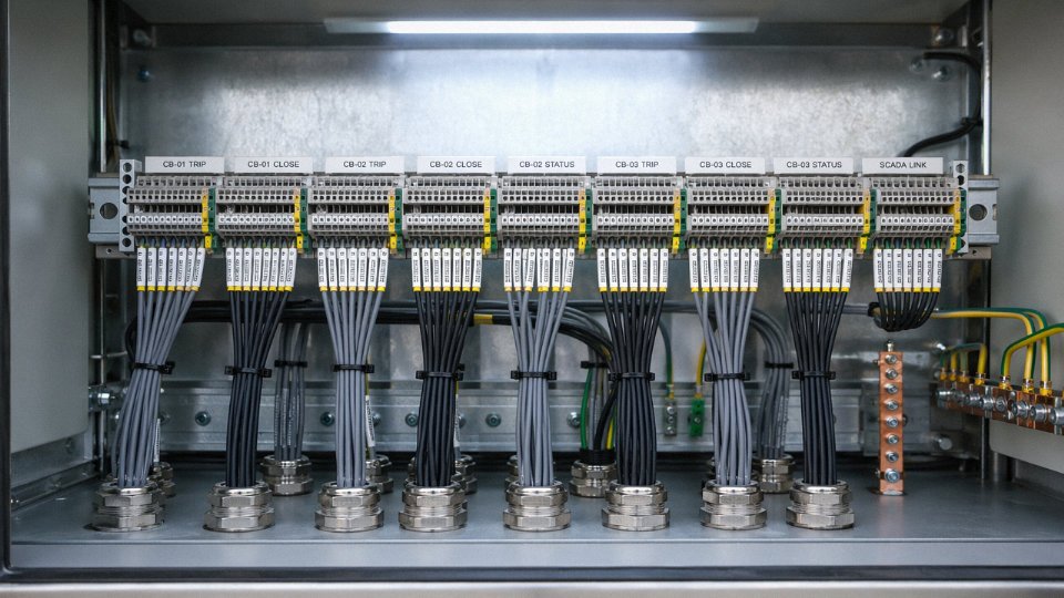
Inside switchgear rooms and substation control buildings, control cables carry three broadly distinct signal types: protection relay outputs that must energize trip coils within milliseconds of a fault condition, status signals that report breaker and isolator positions back to SCADA, and interlock logic signals between panels. None of these carry significant current — a trip coil circuit might run at 48 V DC or 110 V DC, drawing a few hundred milliamps — but the functional demand is absolute. The cable either delivers the signal cleanly or it doesn’t, and “mostly works” is not an acceptable performance standard when you’re clearing a high-fault-current event.
Cross-sections in these circuits are typically modest, 1.5 mm² to 4 mm², but core counts can be high — a complex protection panel might require 19-core or even 37-core cables to consolidate runs from one marshalling kiosk to another. Keeping conductor resistance low and insulation integrity consistent over 20-plus year asset lifetimes is the real specification challenge here, not raw current capacity.
Fire Performance: Why LSZH and Fire-Resistant Ratings Are Not Optional
Substation buildings and cable basements concentrate large numbers of cables in confined spaces. In a fire, ordinary PVC insulation releases hydrogen chloride gas — dense, corrosive, capable of damaging live equipment in adjacent panels before the fire itself reaches them. That’s why most transmission and distribution operators now mandate LSZH (low-smoke zero-halogen) sheathing for indoor control cable installations, and why fire-resistant variants rated to IEC 60331 are specified for circuits that must stay functional during a fire event: emergency shutdown sequences, fire suppression actuator feeds, and evacuation alarm circuits.
IEC 60331 specifies that fire-resistant cables must maintain circuit integrity when exposed to flame at 750°C–800°C for a minimum of 90 minutes under specified test conditions.True
IEC 60331-21 covers flame application at 750°C for cables up to 20 mm diameter; the 90-minute endurance requirement is standard for fire-resistant control cables used in critical infrastructure applications.
IEC 60332-3 addresses the spread of flame in bundled cable installations — relevant because substation cable routes are almost never a single cable run. Specifying to both standards simultaneously is routine on any serious utility project.
Armored Cables for Outdoor and Underground Runs
Outdoor substations are rough environments for cables. Runs between equipment kiosks cross gravel yards, go underground through duct banks, and sometimes simply get surface-laid along cable trenches where ground movement, moisture ingress, and the occasional overzealous groundskeeper with a spade are all real hazards. Steel wire armored (SWA) or aluminum wire armored (AWA) construction provides the mechanical protection that unarmored cables simply can’t offer in these conditions. AWA is usually preferred where weight matters or where aluminum-sheathed cable minimizes any galvanic corrosion risk in wet environments. The armor also provides a degree of rodent resistance — not total immunity, particularly against persistent burrowing, but meaningfully better than an unarmored equivalent.
Renewable Energy: Flex Cycles and UV Exposure
Wind turbines introduce a mechanical demand that most substation engineers never deal with: continuous torsional flexing. As a nacelle yaws to track wind direction, every cable running through the tower and into the nacelle twists repeatedly. Over a turbine’s 20-year design life, that adds up to hundreds of thousands of flex cycles. Control cables specified for this application need finely stranded conductors — Class 5 or Class 6 stranding — and an elastomeric insulation compound, often EPR or a purpose-formulated TPE, rather than standard PVC. Using a standard factory-automation control cable here is a predictable failure mode: the insulation cracks, the conductors fatigue-fracture, and you’re pulling new cable through a tower that was never designed for easy cable replacement.
Solar farms present a different set of problems. Control cables for tracker actuators, inverter communications, and combiner box monitoring run outdoors across large arrays with essentially no shade. UV degradation of the outer sheath, temperature cycling between ground-level cold nights and mid-afternoon heat (surface temperatures at cable tie points can reach 70–80°C in hot climates, depending on color and exposure), and occasional standing water in cable channels all accelerate aging. UV-stabilized XLPE or LSZH-HF sheathing with a rated operating temperature of at least +90°C is a reasonable baseline specification.
Induced Voltage and Separation Requirements
One aspect that catches engineers early in their substation careers: even a low-voltage control cable running parallel to a high-voltage conductor can pick up enough inductively or capacitively coupled voltage to cause problems. In practice, false relay operations have been traced back to inadequate cable separation — control cables routed too close to 11 kV or 33 kV bus runs picking up enough noise to trip sensitive protection relays. The fix is usually straightforward: maintain required separation distances per IEC 61936-1 guidance, use screened control cables in congested routes, and ground the screen at one end only to avoid circulating currents. Twisted pair cores within multi-core cables help reject common-mode interference. It sounds like detail work — and it is — but getting it wrong costs far more in nuisance trips and investigation time than the small upfront cost of specifying screened cable from the start.
Control Cables in Building Automation, HVAC, and Smart Infrastructure
Buildings have gotten complicated. A mid-sized commercial office block built today might have several hundred control loops running simultaneously — HVAC zones, fire suppression, access control, elevator logic, lighting ballasts, leak detection — all feeding into a central building management system (BMS). The physical wire connecting those field devices to the control processors is, in almost every case, a shielded control cable. Not Ethernet, not fiber, not wireless. A conventional, copper-conductor, shielded control cable.
How Control Cables Tie a BMS Together
The BMS is really just a supervisory layer. Below it, thermostats signal setpoints, damper actuators move air volume, chiller plant controllers respond to load demand, fire suppression panels hold dry-pipe valves, and access readers release or deny entry — all over hardwired connections to central processors or distributed controllers. Typical conductor cross-sections in this environment run from 0.5 mm² to 1.5 mm², usually with 2 to 7 cores, though larger cable assemblies going into the main panel room might run higher core counts. The signal levels are low: 24 V DC is common, with some legacy systems still running 0–10 V analog. Noise immunity matters. An unshielded cable running parallel to a lighting circuit or a VFD output will pick up enough interference to cause spurious readings or nuisance faults. In practice, most competent MEP engineers specify overall-shielded or individually-shielded pairs almost by default for BMS applications, even where the spec sheet doesn’t explicitly require it.
HVAC Signal Cables: The Specifics
For air handling unit (AHU) control, the dominant signal standard is 4–20 mA for analog sensors — temperature, differential pressure, CO₂ concentration — because that current loop is inherently noise-resistant and can run over longer cable runs, often 100–400 m depending on cable gauge and source impedance. Two-core and three-core shielded cables, with drain wire, are the workhorses here. The third conductor typically carries ground or a common reference. Some European and Asian installations use 0–10 V signaling, which is fine over short runs but becomes problematic beyond roughly 50–80 m without proper cable selection, because line resistance starts eating into your signal range. This is an underappreciated spec error that shows up as an actuator that never quite reaches 100% open.
Hardwired vs. Protocol-Based: The Real Hybrid Reality
BACnet and Modbus over Ethernet have genuinely displaced a lot of point-to-point wiring in smart buildings, and that trend is real. But anyone who has commissioned a building knows that the actuator power-and-signal cable, the safety interlock wiring, and fail-safe override circuits remain hardwired — deliberately. A network packet can be dropped, a switch can reboot, a VLAN can be misconfigured. A hardwired safety interlock cannot. Smoke control dampers, stairwell pressurization fans, and elevator recall circuits in most jurisdictions legally cannot rely on software-routed signals alone. Control cables are the physical backstop.
Plenum, Riser, and Fire Classification Requirements
North American installations are governed by NEC Article 800 and UL 910 for plenum-rated cables. Plenum spaces — the cavities above drop ceilings or below raised floors used for air return — require cables with very specific low-flame, low-smoke characteristics because a cable fire in a plenum moves smoke directly through the HVAC system into occupied spaces. Plenum-rated cables are noticeably more expensive than riser-rated alternatives, sometimes 30–60% higher depending on conductor size and market conditions, and substituting a riser-rated cable in a plenum space is a code violation that will fail inspection and create real liability in a fire event.
European projects follow the Construction Products Regulation (CPR) reaction-to-fire classifications. The scale runs from Fca at the bottom to A2ca at the top. Commercial buildings in most EU member states require at minimum Dca or Cca in circulation areas; critical infrastructure and transport hubs typically specify B2ca or higher. Getting this wrong at procurement is a documented problem — a cable that is perfectly acceptable for an industrial installation may fail CPR compliance for a European public building tender.
Plenum-rated cables (UL 910) reduce smoke toxicity in HVAC air-return spaces compared to standard PVC cables during a fire event.True
UL 910 testing requires cables to meet strict limits on flame spread and optical smoke density when tested in a simulated plenum environment. Standard PVC cables produce significantly higher smoke and toxic gas yields, which is why substitution in plenum spaces is prohibited under NEC.
Low-Smoke Halogen-Free Cable Demand
The push toward LSHF (low-smoke halogen-free) or LSZH cable compounds has accelerated meaningfully over the past decade, driven partly by regulation and partly by hard lessons from building fires where conventional PVC cables produced dense, toxic smoke that incapacitated occupants before they could evacuate. Tunnels, metro stations, airports, hospitals, and high-occupancy commercial towers are the primary specification environments. LSHF control cables typically use polyolefin-based insulation and jacket compounds; they cost more than standard PVC equivalents — roughly 15–40% depending on conductor cross-section and market pricing — but in any project where occupant life safety is a genuine design criterion, that cost differential is simply part of the spec.
Operating temperature ratings for building control cables generally run from -15°C to +70°C for standard PVC types, extending to -40°C to +105°C with XLPE or silicone rubber insulation for mechanical rooms, rooftop equipment, or cold-climate installations where cable brittleness at low temperatures is a real concern, not a theoretical one.
Control Cables in Oil, Gas, and Petrochemical Facilities — Surviving Extreme and Hazardous Environments
Of all the environments where control cables operate, oil and gas is the one that genuinely keeps cable engineers up at night. The combination of flammable atmospheres, corrosive chemicals, mechanical abuse, and extreme temperatures — sometimes all present simultaneously on a single offshore platform — creates a specification challenge that punishes shortcuts fast.
Hazardous Area Classification and What It Actually Demands from the Cable
ATEX (EU Directive 2014/34/EU) and the internationally aligned IECEx scheme divide explosive atmospheres into zones based on how frequently a flammable atmosphere is present. Zone 0 is continuous or near-continuous presence; Zone 1 is likely under normal operation; Zone 2 is only in abnormal conditions. The cable itself doesn’t receive an ATEX marking in isolation — the certification applies to the equipment and system — but the cable must be rated and installed in a way that cannot itself become an ignition source. That means selecting cables with appropriate temperature ratings (T-class), ensuring that the cable sheath and armor cannot generate friction sparks in the installation environment, and confirming that the cable termination and gland arrangement is compatible with the zone. Get the gland specification wrong in a Zone 1 area and the best cable in the world provides no protection.
Intrinsically Safe Circuits — Where Cable Parameters Become Safety-Critical Numbers
Intrinsically safe (IS) design per IEC 60079-14 is probably the most misunderstood area in control cable procurement for oil and gas projects. In an IS circuit, the cable is not just a conductor — its distributed capacitance and inductance are part of the safety calculation. Exceed the permitted cable capacitance (typically in the range of a few hundred nanofarads, depending on the associated apparatus entity parameters) or inductance limits, and the stored energy in the cable itself can, under fault conditions, release enough energy to ignite a flammable atmosphere. Cable length therefore becomes a hard constraint, not a convenience. IS cables are purpose-designed with low capacitance between cores, often using twisted-pair construction with defined geometry, and they must be individually screened and separated from non-IS circuits in cable trays — not merely bundled in a different color.
Intrinsically safe control cables in IEC 60079-14 compliant systems must have capacitance and inductance values that keep total circuit energy below ignition thresholds for the relevant gas group.True
IEC 60079-14 requires that the cable's distributed capacitance (Cc) and inductance (Lc) per unit length be factored into the overall IS loop assessment against the entity parameters of the associated apparatus. Exceeding permitted cable length or using unqualified cable can invalidate the IS protection concept entirely.
Mechanical and Chemical Resistance in Refineries and Offshore
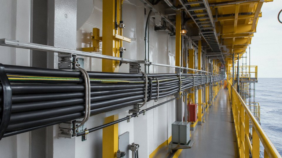
On an offshore platform or a refinery unit, control cables route through environments that would destroy a standard industrial cable within months. Hydrocarbon condensate, H₂S at concentrations well above immediately dangerous levels, seawater spray, and the aggressive alkaline or chlorinated cleaning agents used during turnarounds all attack cable sheaths. Armored cables — typically with steel wire armor (SWA) or, in weight-sensitive offshore applications, aluminum wire armor — provide mechanical protection against impact and rodent ingress. The outer sheath compound matters equally: mud-resistant, oil-resistant LSZH or CSP (chlorosulfonated polyethylene) compounds resist hydrocarbon swelling and maintain flexibility across a wider temperature band than standard PVC. PVC outer sheaths are still used in sheltered cable ducts onshore, but exposing them to crude oil splash or aggressive cleaning chemicals is asking for premature failure, usually visible as surface crazing within one to two seasons.
Temperature Extremes at Both Ends
Arctic pipeline monitoring installations in northern Russia, Alaska, or Canada routinely see ambient temperatures of -50°C to -60°C, sometimes colder during installation. At those temperatures, a standard PVC-insulated cable becomes brittle enough to crack during coiling or pulling — sometimes without any visible damage, leaving a latent fault that only shows up under electrical test or, worse, in service. Cold-flexible compounds, typically based on specially formulated polyurethane or low-temperature-rated XLPE with plasticizer systems designed for sub-zero performance, allow cables to remain pliable down to around -60°C. Specify the cold-bend test temperature explicitly; don’t assume that a cable rated for -40°C continuous operation will survive installation at -55°C.
At the hot end, cables routed near process heaters, crude unit furnaces, or flare stack base structures can see surface temperatures well above 100°C — occasionally above 150°C during upset conditions. Standard XLPE, rated to roughly 90°C continuous (105°C in some formulations), isn’t enough here. Silicone rubber insulation handles temperatures up to around 180°C to 200°C depending on the compound, and PTFE insulation pushes that boundary further still. The trade-off is mechanical robustness: silicone is softer and more susceptible to physical damage, so it usually needs armoring in any location where cable contact or impact is possible.
What Procurement Teams Face on Oil and Gas Projects
Sourcing control cables for a major oil and gas project is not a standard catalog exercise. Most upstream and downstream projects operate under project-specific technical specifications that overlay IEC standards with additional requirements — Shell DEP (Design and Engineering Practices), Saudi Aramco SAES electrical standards, BP GIS specifications, and similar documents from other operators. These specifications can require materials traceability back to the melt heat for conductors, third-party factory acceptance testing (FAT) witnessed by the client’s inspection agency, specific drum length tolerances, and drum-by-drum test certificates. Lead times for armored, IS-rated, or cold-flexible cables in unusual core counts — say, 19-core or 27-core — can run from 10 to 16 weeks from a qualified mill, longer if the project specification calls for a non-standard insulation system or a specific certification mark not held by the local plant.
The practical advice: lock down the cable schedule and the approved vendor list early. Substituting cable types late in a project because the original specification couldn’t be met on time is one of the more reliable ways to create a procurement nightmare, especially when the substitute requires revalidation under the IS loop calculations.
Control Cables in Transportation Infrastructure — Rail, Marine, and Tunnels
Transportation environments are some of the most punishing places you can route a cable. Unlike a static factory panel or a substation marshalling cabinet, a train bogie is moving constantly, flexing, vibrating, and swinging through temperature extremes — sometimes within the same 30-minute trip. The demands are different in kind, not just degree.
Rolling Stock: From Driver’s Desk to Bogie
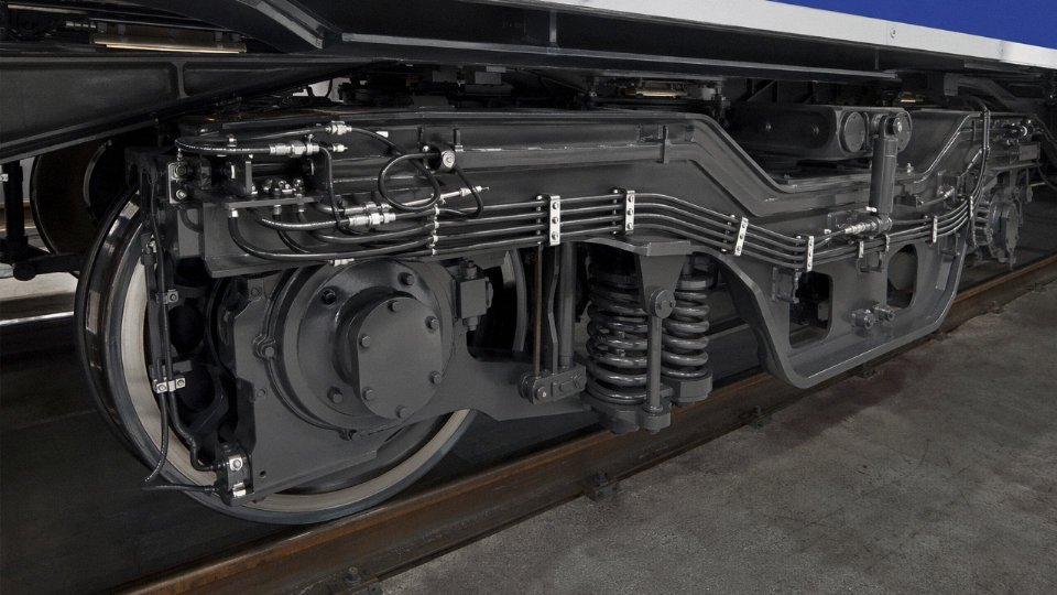
Inside a rail vehicle, control cables carry signals between the driver’s control desk and traction control units, brake actuators, door interlock systems, and passenger information displays. That sounds straightforward until you consider what the cable actually goes through. A cable running from the cab down into the underframe passes through a heated interior, then gets exposed to sub-zero air blast under the vehicle body, then enters the bogie where it loops through a pivot point that flexes roughly 40 to 60 thousand times over a typical service interval — numbers that vary significantly depending on line profile and vehicle speed.
Traction motor EMI is a persistent headache. High-frequency switching noise from modern IGBT inverter drives can corrupt low-voltage control signals unless cables are properly shielded and the shield is terminated correctly at both ends. In my experience, a surprisingly high proportion of intermittent faults on rail vehicles trace back not to the cable itself but to a corroded shield drain wire or a poorly landed screen termination that was assembled in a rush during commissioning.
Conductor construction matters here. Coarse-stranded conductors — the kind you might run through a fixed industrial conduit — will work-harden and crack at flex points inside a bogie within a few years. Fine-stranded, flexible-class conductors (Class 5 or Class 6 per IEC 60228) are the practical minimum. Cross-sections in rolling stock control wiring typically run 0.5 mm² to 2.5 mm², with the lower end covering signal and interlock circuits and the upper end covering brake and door-control loops where slightly more current is involved.
EN 50264 and EN 45545 — Not Paperwork, Actual Lifesavers
Fire performance in passenger rail is regulated, not optional. EN 45545 classifies railway vehicles by hazard level and occupancy — a metro car running underground at peak hour is R22 or R23, the most demanding categories — and cables must meet corresponding fire performance requirements covering flame propagation, smoke density (optical), and toxic gas emission. EN 50264 defines the cable construction standards that deliver those fire performance classes.
EN 45545-2 distinguishes between cables used in different hazard levels of railway vehicles, with underground and high-density passenger environments facing stricter requirements than surface freight applications.True
EN 45545-2 defines hazard level categories (HL1, HL2, HL3) and maps them to vehicle operating environments; underground passenger stock typically requires HL3-compliant materials, which impose the strictest limits on flame spread, smoke opacity, and toxicity.
The practical consequence of getting this wrong is severe. Smoke from burning PVC-insulated cable is dense enough to disorient passengers within minutes. Specifying LSZH (low smoke, zero halogen) compounds is not about passing a procurement checklist — it is about whether people can find the exit.
Marine Applications: IEC 60092 and the Classification Societies
Shipboard control cable specification is governed by IEC 60092-376 for instrumentation and control applications, but the classification societies — Lloyd’s Register, DNV, Bureau Veritas — each layer additional requirements on top, and those requirements can differ in detail. Procurement teams handling marine projects learn quickly to confirm which society is certifying the specific vessel before placing a cable order.
The fundamental challenge at sea is the environment: salt-laden humid air, pooling bilge water, fuel and hydraulic oil contamination, and mechanical vibration from main propulsion. Engine room cables need oil-resistant outer sheaths — EPR or CSPE compounds rather than standard PVC — and fire performance classes appropriate for spaces where a cable fire can cut propulsion and steering simultaneously.
Cable cross-sections in marine control circuits typically range from 0.75 mm² to 4 mm², depending on circuit length and the current-carrying requirements of the actuators being controlled. Multi-core counts can run surprisingly high on complex vessels; a 19- or 27-core cable running from a bridge console to a machinery control room is not unusual.
Tunnels and Metro Systems: Keeping the Evacuation Path Open
Road tunnels and metro infrastructure share a specific requirement that sets them apart from most other environments: the control cables for ventilation fans, emergency lighting, PA systems, and fire detection must continue functioning while the fire is happening. Not just before it. During it.
This drives the fire-resistance specification — typically IEC 60331 or EN 50200 — alongside LSZH sheath requirements. A control cable rated to maintain circuit integrity for 90 minutes at 750°C gives the ventilation and evacuation systems time to operate while passengers and emergency services are still in the tunnel. Specifying a standard flame-retardant cable instead of a fire-resistant one in this application is not a minor substitution. It is the kind of mistake that ends careers and, in a worst case, costs lives.
Tunnel environments also bring installation challenges that are easy to underestimate: high humidity, cleaning-chemical wash-down exposure, and very long cable runs where voltage drop must be checked even on 24 V DC control circuits.
How to Select the Right Control Cable — A Practical Specification Checklist for Engineers and Buyers
Getting the specification wrong costs more than the cable. A misjudged insulation compound or an overlooked shielding requirement can mean nuisance faults at commissioning, full cable replacement after six months, or — in a hazardous area — a compliance failure that halts production. The following checklist reflects how experienced engineers actually approach this, not a textbook abstraction.
Step 1 — Define the Electrical Parameters First
Start with voltage rating. Most industrial control circuits run at 300 V or 600 V; specifying a 300 V cable on a 600 V circuit is an obvious mistake, but it happens when purchasing is done from a generic BOM without an electrical review. Confirm signal type early: a 4–20 mA analog loop, a 24 V DC discrete input, and a pulse encoder output all have different sensitivity to interference. If any signal is analog or high-frequency pulse, shielding is almost certainly required — either individual pair shields, an overall braid, or both, depending on the noise environment. Skipping the shield to save cost and then retrofitting ferrite cores or rerouting cables around VFD panels wastes far more time than the upfront specification effort.
Step 2 — Assess the Mechanical Environment
Static conduit installation and dynamic flex in a cable carrier are fundamentally different problems. A cable running in a drag chain on a machine tool might flex through millions of cycles; it needs a stranded conductor with a fine wire count, a jacket compound that resists cracking under repeated bending, and a minimum bend radius the manufacturer actually guarantees under dynamic load — not just the static figure quoted in a datasheet. For vertically hung installations, check tensile load: long vertical runs carrying their own weight can work individual conductors loose at terminations over time, particularly in elevator shafts or offshore risers. If rodents are a known site problem — and in agricultural facilities or older cable tunnels, they very much are — a nylon outer jacket or a metallic armor adds a layer of protection that’s cheap relative to the failure it prevents.
Step 3 — Match the Compound to the Chemistry
Operating temperature range drives insulation selection more than almost anything else. PVC covers roughly -15 °C to +70 °C and suits the majority of indoor industrial applications. XLPE extends that to around -40 °C to +90 °C and handles outdoor or higher-temperature environments better. Polyurethane (PUR) is the default choice where oils and cutting fluids are present — a machine shop environment will degrade a standard PVC jacket noticeably within a year or two. Silicone is reserved for genuinely high-temperature zones: furnace surrounds, welding equipment, areas near steam lines. UV exposure matters outdoors even in moderate climates; a UV-stabilized compound or a sunlight-resistant rating should be explicitly specified, not assumed.
Step 4 — Map the Fire Performance Requirements
This step gets skipped or deferred more than any other, and it causes the most expensive late-stage changes. Identify the installation location: open cable tray in a process plant, plenum space in a commercial building, a rail vehicle, a tunnel, a classified hazardous area. Each maps to specific standards. IEC 60332-3 covers flame spread for bundled cables. IEC 60331 applies where circuit integrity under fire matters — emergency systems, for instance. EN 45545 applies to railway rolling stock. ATEX or IECEx certification is non-negotiable in Zone 1 or Zone 2 explosive atmospheres. CPR (Construction Products Regulation) Euroclass ratings apply to fixed installations in EU buildings. Getting a test certificate after the cable is already installed is not an option.
Step 5 — Count Cores Carefully and Build In Spares
Work from a finalized I/O list or wiring diagram, not a rough count. A 20% spare core allowance is a reasonable rule of thumb for most projects, though complex automation systems with frequent engineering changes warrant more. Size the conductor cross-section for both current capacity and voltage drop over the actual cable run length — a 0.75 mm² conductor is adequate for a short 24 V digital signal loop but will cause problems on a 4–20 mA analog run over 300 m or more.
A 20% spare core allowance is a widely recommended practice for industrial control cable installations to accommodate future expansion and field modifications.True
This figure is consistently referenced in industrial wiring design guides and commissioning engineering practice to reduce the cost and disruption of adding circuits to existing installations.
Step 6 — Work the Supply Chain Requirements Into the Specification Early
Third-party certification, Factory Acceptance Testing, specific drum lengths, custom jacket printing — these are not afterthoughts. A large infrastructure project may require witnessed FAT at the manufacturing facility, which means the manufacturer needs documented test equipment and the capacity to schedule it. Custom print legends (circuit IDs, project numbers, installation codes printed continuously on the jacket) are straightforward for a manufacturer with the right setup but can add lead time if the request arrives late. Confirm export documentation requirements — country-of-origin certificates, material traceability records, ROHS compliance declarations — before placing the order, not after it ships.
Frequently Asked Questions About Control Cable Applications
Can I use a power cable instead of a control cable to save cost?
Short answer: don’t. Power cables are designed to carry current to a load — they’re built around conductor sizing for ampacity, not signal integrity. A standard power cable has two, three, or four cores at most, no shielding, and insulation chosen for dielectric strength under load voltage rather than for low capacitance or noise rejection. When you run a PLC output signal or a 4–20 mA analog loop through an unshielded power cable routed near motor feeders, you’re essentially building an antenna. The result is erratic relay chatter, false sensor readings, or spurious drive trips — all of which are infuriating to diagnose because the wiring looks fine on a visual inspection.
There’s also a code compliance issue. In most jurisdictions, IEC 60364 and equivalent national standards treat control and power wiring as separate categories with distinct installation rules. Substituting one for the other can invalidate a machine’s CE marking or fail an electrical inspection outright. The cost “saving” usually disappears the first time a commissioning engineer has to spend two days chasing a noise fault.
What is the difference between a shielded and unshielded control cable, and when do I need shielding?
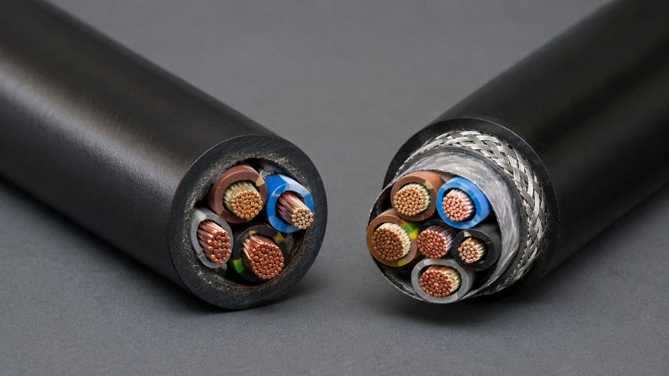
Foil shields — typically aluminum-polyester laminate — give coverage of around 100% against high-frequency interference but are fragile under repeated flexing. Braided shields, usually tinned copper, run 85–98% coverage depending on braid angle and are far more durable in moving applications. Some cables combine both, which is worth specifying in harsh EMC environments even if it adds cost.
The practical rule: if your cable runs within roughly 300–500 mm of a VFD, servo drive, welding cable, or any high-frequency switching source, use a shielded cable. Full stop. The same applies any time your installation requires a formal EMC test report. Unshielded cable is acceptable in low-noise environments — simple on/off control circuits in a clean panel room, for instance — but it’s a gamble in most real plant environments. Ground the shield at one end only for low-frequency analog signals; both ends for high-frequency digital signals. Getting that wrong defeats the purpose entirely.
How many cores do I need in my control cable?
Count your discrete I/O signals first, then add your analog pairs (each 4–20 mA loop needs two cores, sometimes three if you’re running a separate screen drain). Once you have that number, add a spare margin of 20–25% — not because engineers enjoy waste, but because a run pulled through conduit or a cable tray is expensive to replace when you need two extra cores for a sensor that wasn’t in the original scope. In practice, if your count lands at, say, 13 active cores, specify a 16-core cable rather than a 14.
Whether you can combine power and signal in a single cable depends on the application. Some machine tool builders do it to reduce harness count; most process instrumentation engineers refuse on principle because of crosstalk risk. Check the end-equipment manufacturer’s specification before combining.
What does LSZH mean and do I always need it?
Low-smoke zero-halogen insulation doesn’t burn any “cleaner” than standard PVC in terms of ignition temperature, but what happens when it does burn is very different. Standard PVC releases hydrogen chloride gas — corrosive to electronics, toxic to people in enclosed spaces, and capable of destroying switchgear in a server room or substation long after the fire is out. LSZH compounds replace the halogenated flame retardants with mineral-based alternatives that produce dense but non-corrosive smoke.
LSZH is mandatory — not optional — in metro tunnels, road tunnels, marine vessels, offshore platforms, data centers, and most public buildings in Europe and increasingly in Asia. For a well-ventilated outdoor industrial site with good emergency egress, standard PVC or XLPE is usually acceptable and meaningfully cheaper. Don’t over-specify LSZH everywhere just to be cautious; it affects flexibility in cold temperatures and can complicate termination with standard tooling.
How do I verify that a control cable manufacturer meets international quality standards?
ISO 9001 certification is a baseline, not a guarantee. What matters more is whether the manufacturer can produce third-party test reports from accredited laboratories — not their own internal lab — covering conductor resistance, insulation resistance, voltage withstand, and where applicable, flame propagation and smoke density. IEC 60227, IEC 60332, or UL 508 product certifications tied to specific cable constructions carry real weight.
Ask for material traceability documentation: batch records for copper rod, insulation compound, and sheathing material. A manufacturer who hesitates on that request is worth scrutinizing. Factory Acceptance Testing capability matters for large or critical orders — the ability to witness conductor cross-section verification, spark testing, and conductor continuity checks on-site or via a third-party inspector is a genuine differentiator.
Jinda holds ISO 9001 certification and supports third-party factory acceptance testing for international project orders.True
Relevant to procurement managers who need documented quality assurance beyond a supplier's self-reported claims, particularly for infrastructure or industrial automation projects where cable traceability is a project requirement.
What is the typical lifespan of a control cable in industrial service?
A correctly specified and properly installed control cable in a static application — fixed conduit, stable temperature, no mechanical stress — should realistically last 20–30 years. The insulation is usually what limits service life, and XLPE holds up better than PVC at elevated temperatures; silicone rubber outlasts both but costs more and is harder to terminate neatly.
Flex-rated cables are a different story. Continuous-flex designs used in drag chains or robotic arms are typically rated for somewhere between 5 and 10 million flex cycles depending on bend radius, cable diameter, and conductor stranding class. Run them at tighter-than-specified bend radii and that number drops fast — conductor fatigue cracking at terminations is the usual failure mode, and it tends to show up as intermittent faults that are genuinely maddening to find. In my experience, poor termination practice and chronic overheating from undersized conduit fill cause more premature cable failures than any material defect. Those are installation problems, not product problems, but they end up looking the same on a maintenance report.