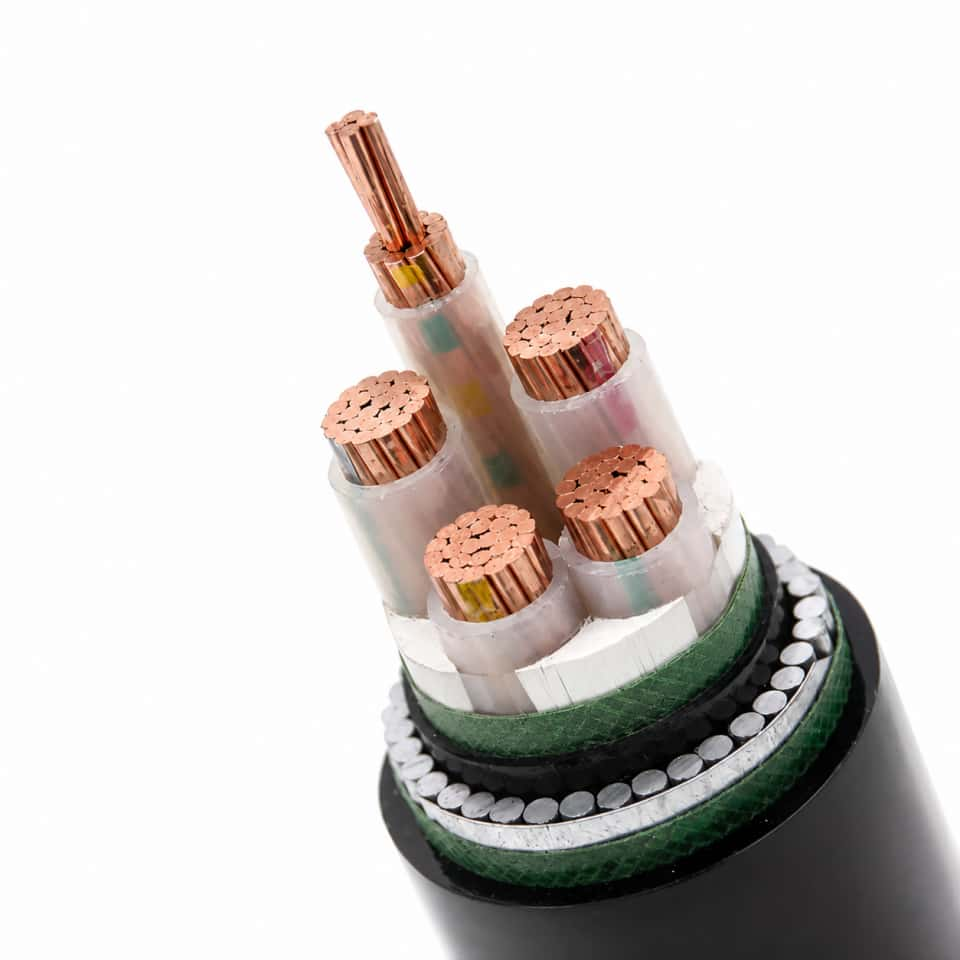
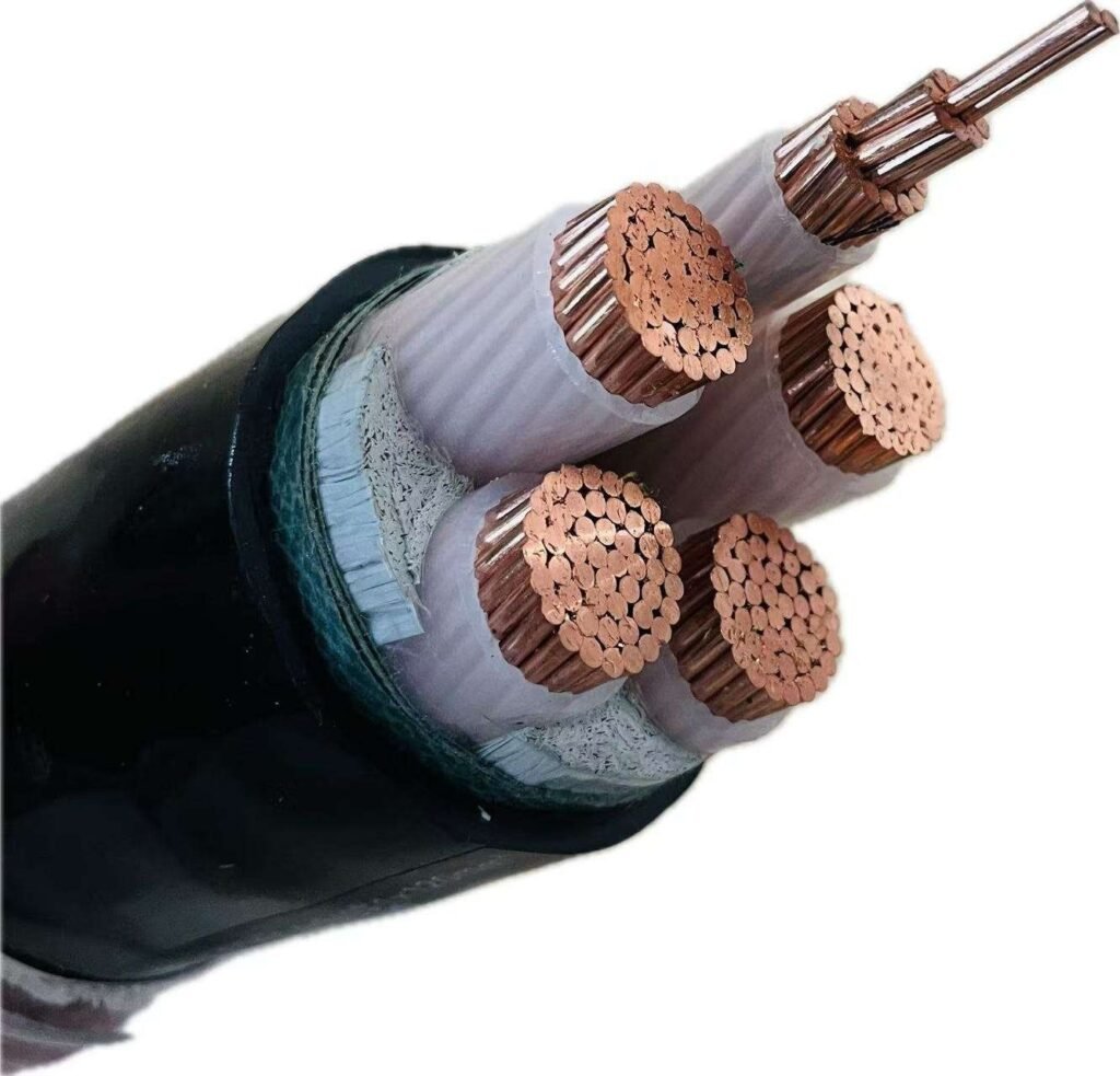
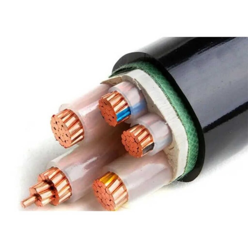
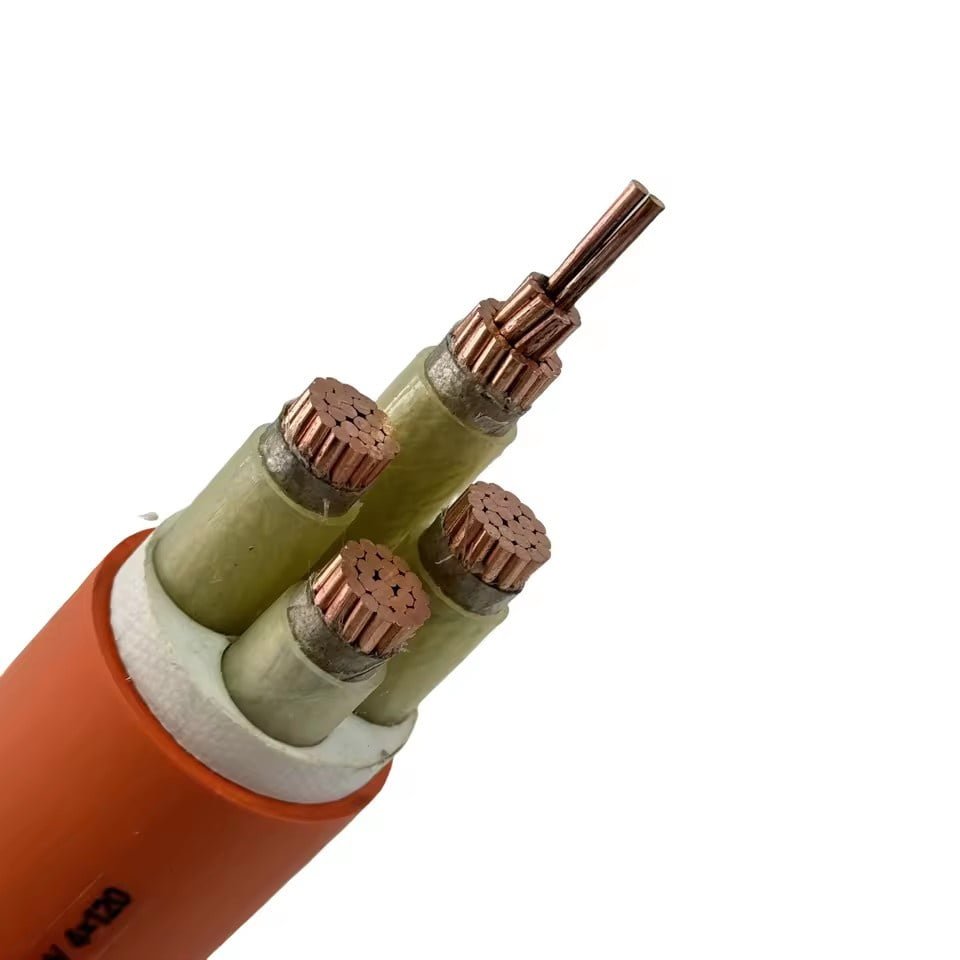
Specify the wrong wire type on a bill of materials and the downstream effects compound fast — insulation that softens under load cycling, conductors that corrode in six months instead of six years, ampacity ratings that looked fine on paper until a breaker starts nuisance-tripping on a 60% load. The rework cost is rarely just the wire itself; it’s the labor to pull and re-pull, the production hours lost, sometimes a full UL or CE re-certification if the substitution touches a listed assembly. Getting the wire type right at the specification stage is the cheapest decision you will make on any electrical project.
The five fundamental types of wire are: solid wire, stranded wire, coaxial wire, twisted pair wire, and shielded wire. Each is defined by its conductor construction, insulation system, and the signal or power environment it is designed to handle. Choosing among them depends on flexibility requirements, frequency range, current capacity, and exposure to electrical noise or mechanical stress.
What makes this more complicated in practice is that these categories overlap — a shielded wire can also be stranded, a twisted pair can be coaxial — and the wire market has grown dense enough that global cable procurement alone now tracks somewhere around USD 225 billion annually, projected to push past USD 340 billion by the early 2030s. That volume reflects genuine engineering diversity, not redundancy. Understanding what separates these five types, and when each one fails if misapplied, is the foundation of any serious procurement or design decision.
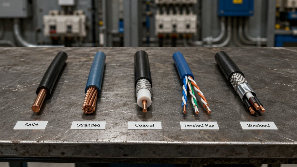
Solid Wire: Construction, Electrical Characteristics, and Best-Fit Applications
Solid wire is exactly what the name says: a single, unbroken metallic conductor drawn down to a target gauge through a series of progressively smaller dies, then covered with an insulation layer — PVC for general indoor use, XLPE where heat resistance or wet-location ratings matter, THHN for conduit runs in commercial and residential panels. There is no stranding, no lay angle, no bundle geometry to worry about. One conductor, one cross-section, done.
Copper is by far the dominant material. Its resistivity sits around 1.68 × 10⁻⁸ Ω·m at 20°C, and that figure holds well in solid form because the entire cross-section carries current uniformly at DC and low AC frequencies. Aluminum solid wire is used in utility distribution and some larger feeder applications — its resistivity runs roughly 2.82 × 10⁻⁸ Ω·m — but aluminum needs anti-oxidant compound at every termination point without exception, something installers occasionally skip and then spend a long time regretting.
Skin Effect: Where Solid Wire Starts to Lose Ground
At low frequencies, solid conductor performance is essentially ideal. The problem creeps in as frequency rises. Skin effect — the tendency of AC current to concentrate near the conductor surface — becomes meaningful somewhere above roughly 1 kHz for copper conductors in typical power wire gauges. Below that threshold, solid wire is fine for nearly every power and lighting circuit. Above it, the effective conducting cross-section shrinks, resistance climbs, and you lose the efficiency advantage you thought you were buying. For industrial VFD output wiring or any signal cable running above a few kilohertz, stranded or even litz wire is the correct call. Solid wire simply is not built for those conditions.
Gauges and Code-Referenced Applications
For North American residential and light commercial work under NEC, 12 AWG (approximately 2.5 mm²) solid copper is the standard for 20 A branch circuits — kitchen outlets, bathroom circuits, most general receptacle runs. Step up to 10 AWG (roughly 6 mm², give or take depending on the standard) for 30 A loads like electric dryer outlets. Under IEC 60364 and its national derivatives, the equivalents are 2.5 mm² and 6 mm² respectively, and the cable designation system differs, but the underlying conductor sizing logic is consistent.
Fixed in-wall wiring, underground direct burial using USE-2 rated cable, conduit runs between panels, and low-voltage landscape lighting circuits are the natural home for solid wire. These installations share one characteristic: once the wire is pulled and terminated, it essentially never moves again.
Termination Reliability
One underappreciated advantage on the installation floor is how solid conductors behave at screw terminals and push-in connectors. A stranded conductor, if not properly tinned or ferrule-crimped, can splay individual strands during insertion — one stray strand bridging to an adjacent terminal is how short circuits happen quietly inside junction boxes. Solid wire seats cleanly, stays where you put it, and maintains consistent contact pressure over time. Push-in spring terminals (the Wago 221 series is everywhere now) grip solid conductors more positively than loose stranded ends.
Where Solid Wire Fails
Repeated flexing will work-harden a solid conductor. The metal fatigues, micro-cracks form, and eventually the conductor fractures — sometimes partially, which is worse than a clean break because the resistance rises unpredictably before the final failure. Any installation involving regular movement, vibration, or a cable that gets repositioned periodically should use stranded wire. Solid wire is not listed for use in portable cords for exactly this reason.
Solid vs. Stranded: A Direct Comparison
| Metric | Solid Wire | Stranded Wire |
|---|---|---|
| Flexibility | Rigid; bends once cleanly, fractures under repeated flex | Flexible; suited for repeated movement |
| DC resistance per meter (typical 2.5 mm² Cu) | Slightly lower — full cross-section utilized | Marginally higher — small air gaps between strands |
| Termination ease (screw/push-in) | Excellent; no stray strands | Requires ferrule or careful twisting |
| Cost per meter (same gauge, same insulation) | Usually 5–15% lower, depending on market and order volume | Slightly higher due to stranding process |
| Typical installation labor time | Faster in straight conduit runs | Faster where routing involves tight bends or flex |
The cost delta between solid and stranded narrows considerably at larger gauges and larger order quantities. For a high-volume residential project specifying thousands of meters of 12 AWG branch circuit wire, that 5–15% difference adds up to a real number on the procurement spreadsheet.
Solid copper wire cannot be used in any conduit installationFalse
Solid copper wire is routinely specified for conduit runs in residential and commercial applications. NEC and IEC 60364 both permit it for fixed conduit installations at the appropriate gauges. The restriction applies to flexible, repeatedly-flexed, or vibration-prone installations, not conduit work.
Stranded Wire: Flexibility Ratings, Strand Counts, and Industrial Selection Criteria
Stranded wire is, at its core, exactly what it sounds like: multiple smaller solid conductors twisted together into a single composite conductor. Simple idea. The engineering detail, though, is where procurement decisions get made or broken.
IEC 60228 Conductor Classes and What They Actually Mean
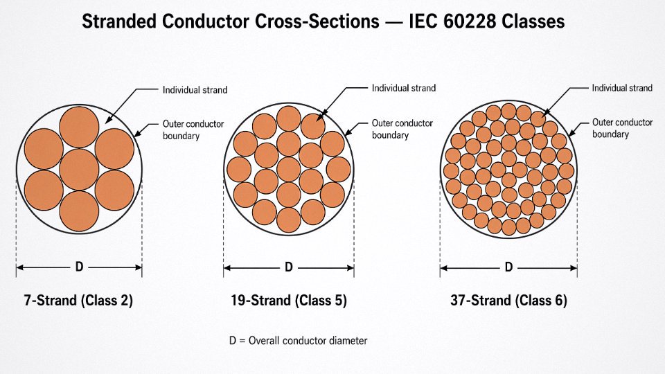
IEC 60228 is the governing standard for conductor classification, and the three classes you’ll encounter most in industrial procurement are Class 2, Class 5, and Class 6. Class 2 is a stranded conductor intended for fixed installation — think power distribution panels, conduit runs, buried cable. It’s stranded for manufacturing flexibility and easier termination, not for dynamic bending. Class 5 is the “flexible” designation: it’s what you find in appliance cords, portable tools, and building wiring that sees occasional repositioning. Class 6 is extra-flexible, built for continuous movement — drag chains, robotic arms, festoon systems, anything that bends thousands of times per day.
The distinction matters more than many buyers realize. Substituting Class 2 for Class 5 in a drag-chain application isn’t a minor spec deviation. You’re looking at conductor fatigue cracking within months rather than years, intermittent faults that are miserable to diagnose, and eventually a full cable replacement on a running production line.
Strand Geometry: Count, Diameter, and Cross-Section
The relationship between strand count and conductor cross-section follows straightforward geometry, but it has real procurement implications. A 7-strand configuration is typical for smaller Class 2 conductors — say, 1.5 mm² to 10 mm². Move to 19-strand or 37-strand and you get finer individual wires, better packing, and significantly improved flex life. A 35 mm² Class 5 conductor might use 196 strands of roughly 0.51 mm each, while a Class 6 version of the same cross-section could run 360-plus strands at around 0.35 mm per wire.
The fill efficiency point is worth flagging for anyone substituting stranded for solid at the same nominal cross-section. Stranded conductors carry marginally lower actual copper fill — the interstices between wires reduce effective conductor area by roughly 3–9%, depending on lay and strand count. For most applications this is absorbed by standard ampacity tables, which already account for it. But if you’re doing a substitution mid-project and recalculating ampacity from first principles, verify actual conductor resistance against the IEC 60228 maximum resistance values rather than assuming cross-section alone tells the full story. Copper resistivity at 20°C is approximately 1.68 × 10⁻⁸ Ω·m; any stranded conductor spec should hit that ballpark per-unit-length when measured against IEC limits.
Flex-Life Testing and What the Numbers Mean in Practice
For Class 6 cable destined for robotics or continuous-flex machinery, UL 62 and IEC 60245 provide baseline electrical performance standards, but flex-life ratings come from application-specific testing — typically a mandrel bend test run to 10 million cycles or beyond for tinned copper Class 6 constructions. The 10-million-cycle figure you see quoted by quality manufacturers depends on bend radius (usually tested at 7.5× to 10× outer diameter), speed, and temperature. Push the bend radius tighter than spec — something that happens routinely when cable clamps are installed by people who didn’t read the datasheet — and actual service life can drop by 60–80%.
Class 6 tinned copper stranded conductors rated for 10 million+ flex cycles must be tested to a specified bend radius; real-world service life drops sharply if installed tighter than the test radius.True
Flex-life ratings from IEC 60245 and robotic cable standards are bend-radius-dependent. Reducing bend radius below the test condition significantly increases strand fatigue stress, reducing cycle life in proportion to the cube of the radius ratio in simplified fatigue models.
Conductor Material Selection
Bare copper is standard for most Class 5 and Class 6 applications in dry or climate-controlled environments. Tinned copper — where each individual strand is electroplated before stranding — is the right call for marine cables, solar DC wiring, humid industrial environments, and anywhere the insulation might be PVC or rubber that could otherwise cause copper sulfide corrosion over time. The tin layer also improves solderability, which matters for some control panel wiring.
Aluminum-stranded conductors are common in overhead distribution and cost-sensitive long runs where weight and material price outweigh conductivity loss. Aluminum’s resistivity runs around 2.82 × 10⁻⁸ Ω·m — roughly 68% higher than copper — so an aluminum conductor needs about 1.6× the cross-section of copper to match resistance on a given run. That’s a straightforward tradeoff on a 500-meter overhead span; it’s a poor one in a tight cable tray.
Mapping Classes to Real Applications
| Conductor Class | Strand Count (typical) | Primary Use Case | Key Spec Concern |
|---|---|---|---|
| Class 2 | 7–19 strands | Fixed power distribution, conduit wiring | IEC 60228 resistance limits |
| Class 5 | 19–196 strands | Appliance cords, portable tools, building flex wiring | Occasional flex, not continuous |
| Class 6 | 196–360+ strands (fine wire) | Drag chains, robotics, festoon, servo cables | Flex-life cycles, bend radius, tinned Cu |
Jinda manufactures Class 5 and Class 6 stranded conductors across its production bases, with dedicated tin-plating lines for marine-grade and photovoltaic wire requirements. For buyers sourcing for renewable energy installations, offshore applications, or high-cycle automation, the availability of tinned Class 6 from a single integrated supplier — rather than buying bare conductor and sending it out for plating — meaningfully reduces lead time and quality risk. Cross-section range runs from 0.5 mm² up through large-format power conductors, with IEC 60228 compliance documentation available as standard for international project specifications.
Coaxial Wire: Impedance Control, Signal Integrity, and Infrastructure Deployment
Coaxial wire looks deceptively simple from the outside — a round cable with a jacket. What’s actually happening inside is a precisely engineered transmission line where every material choice affects impedance, attenuation, and shielding effectiveness in ways that compound badly over long runs or high frequencies if you get them wrong.
Layered Construction and Why Each Layer Matters
Working from the center outward: the center conductor is typically solid or stranded copper (sometimes copper-clad aluminum, or CCA, which cuts cost but raises resistivity and is worth scrutinizing in procurement). Surrounding it is the dielectric — the insulating spacer that, along with conductor diameter, directly determines characteristic impedance. Then comes the shield, then the outer jacket.
Solid polyethylene (PE) dielectric is the baseline — inexpensive, consistent, and widely available, but it has measurably higher dielectric loss than alternatives. Foam PE replaces some of that solid material with air cells, reducing attenuation by roughly 25–35% depending on foam density and manufacturing consistency. That’s a real, practical difference at frequencies above a few hundred MHz. PTFE dielectric is in a different category altogether: it handles continuous operating temperatures above 200°C and survives chemical exposure, which is why you see it in aerospace wiring, military radar feeds, and industrial RF installations near hot processes. You pay roughly 3–5× the price of PE-insulated cable, sometimes more, so it stays in applications that genuinely justify it.
The shield layer is where things get interesting for sensitive installations. A simple aluminum foil bonded to a mylar carrier gives you decent coverage at high frequencies but poor performance at lower ones. Braided copper over foil — or dual-shield and quad-shield configurations — gets you into the range of >90 dB shielding effectiveness, which matters enormously in places like MRI suites, EMC test chambers, and dense DAS environments where even a small ingress of interference corrupts measurements or creates regulatory compliance problems. Quad-shield RG-6 (foil + braid + foil + braid) is the de facto standard for CATV drops into buildings with noise-heavy electrical environments, not because it costs the least but because callbacks are expensive.
Impedance Standards: 50 Ω vs. 75 Ω and the Cost of Mismatching
The two impedance standards you’ll encounter in almost every infrastructure project are 50 Ω and 75 Ω. The 50 Ω standard — cables like RG-8 or LMR-400 — dominates RF transmission, test equipment feeds, Wi-Fi and cellular antenna runs, and data center interconnects where source and load impedances are designed around that value. The 75 Ω standard covers broadcast video, CATV distribution, and satellite downlinks, with cables like RG-6 and RG-11 as workhorses.
Connecting a 50 Ω source to a 75 Ω coaxial run causes signal reflections that degrade return loss and reduce effective power transfer.True
Impedance mismatch creates a reflection coefficient at the boundary; for a 50 Ω to 75 Ω mismatch, the theoretical reflection coefficient is approximately 0.2, corresponding to a return loss of roughly 14 dB — significant in RF systems where even 20 dB is considered marginal.
In practice, mismatched impedance often goes undetected during installation and only shows up as unexplained signal dropout, excessive bit error rates, or amplifier instability. A field engineer with a vector network analyzer can measure it directly; without one, you’re guessing.
Attenuation: The Numbers That Drive Cable Selection
Attenuation increases with frequency, and the differences between cable types are stark enough to determine system feasibility. RG-6 quad-shield loses approximately 6.6 dB per 100 m at 900 MHz — manageable for short CATV drops but a real constraint on antenna runs longer than 30–40 m without an in-line amplifier. LMR-400, with its foam PE dielectric and larger conductor, comes in around 2.7 dB per 100 m at the same frequency. Over a 60 m outdoor antenna feed to a rooftop cell, that difference is roughly 2.3 dB of recovered signal — which in a marginal coverage zone is the difference between a working link and a failed one.
These figures assume clean connectors, correct weatherproofing, and no sharp bends. Each bad connector joint can add 0.3–0.5 dB on its own.
Installation Practices That Actually Affect Performance
Minimum bend radius is frequently ignored until someone kinks a cable during a conduit pull. For most flexible coax, the working minimum is around 10× the outer diameter — so for a 10 mm OD cable, that’s a 100 mm bend radius. Go tighter and you distort the dielectric, shift the impedance locally, and create a reflection point you can’t fix without replacing the run.
Connector choice matters just as much. N-type connectors dominate outdoor RF runs above 1 GHz because of their weatherproof threading and low insertion loss. BNC handles lower-frequency lab and video work well. F-connectors are cheap and ubiquitous in CATV but require proper compression tooling — a push-on or poorly crimped F-connector on an outdoor run will corrode and fail inside 18 months in humid climates. SMA connectors appear on small-cell equipment and test gear; they’re precise and repeatable but not meant for repeated field mating cycles.
Outdoor runs need weatherproof sealing at every connector — self-amalgamating tape over a properly torqued connector, not electrical tape, which degrades in UV exposure within a season or two.
Demand Drivers Through 2030
5G small-cell infrastructure is probably the most significant near-term driver of coaxial cable demand. Small cells require short, low-loss jumpers in high volumes across urban deployments, and the jump from sub-6 GHz to mmWave frequencies pushes designers toward low-loss foam PE or PTFE alternatives where they might have used standard RG cable before. Distributed antenna systems in stadiums, hospitals, and transit networks compound this — a single large DAS installation might consume several kilometers of various coaxial grades across multiple frequency bands.
Broadcast infrastructure is also in a cycle of forced renewal as facilities upgrade to 4K and 8K production, where the higher data rates and tighter signal quality requirements expose marginal cable plants that worked fine at 1080i. That’s a replacement market, not just growth, and it’s active right now in major production markets.
Twisted Pair Wire: Category Ratings, Crosstalk Suppression, and Network Infrastructure Wiring
Why Twisting Works — and Why Twist Rate Is a Manufacturing Specification, Not an Afterthought
Each conductor in a pair carries current in opposite directions. That opposing current flow generates magnetic fields that largely cancel each other when the conductors are tightly twisted together. The tighter the twist, the more effectively those fields cancel — and the better the pair rejects external EMI from motors, fluorescent ballasts, VFDs, and adjacent cable bundles. Every pair within a Cat 6A or Cat 7 cable is manufactured with a different twist rate, typically somewhere in the range of 2 to 6 twists per centimeter depending on the pair position and category target. That difference matters: if two adjacent pairs happened to share the same twist rate, their crosstalk would reinforce rather than cancel. It’s a detail that rarely shows up in a datasheet but separates a genuinely compliant cable from a cheap counterfeit that measures fine on the spool and fails the Fluke test once it’s terminated.
The Category Ladder: Matching Bandwidth to Real Infrastructure Distances
Cat 5e is essentially the floor for any new structured cabling work today — 1 Gbps at 100 m, 100 MHz bandwidth, good enough for office workstations and basic IP cameras. Cat 6 pushes 10 Gbps but only to about 55 m, which catches a lot of planners off guard when they’re laying a floor with deep runs. Cat 6A solves that: 10 Gbps to the full 100 m channel, 500 MHz bandwidth, and the minimum standard for any new data-center horizontal cabling or PoE++ deployment. Cat 7 adds individually shielded pairs plus an overall shield (S/FTP), 600 MHz bandwidth, and 10 Gbps at 100 m — it’s genuinely useful in EMI-heavy environments but requires proprietary GG45 or TERA connectors, which complicates procurement. Cat 8 is the outlier: 25 or 40 Gbps, but only at 30 m, so it’s purpose-built for top-of-rack switch-to-server links inside a data center cabinet row, not floor distribution.
Getting the category wrong in the design phase is an expensive mistake. Pulling Cat 6 through conduit, then discovering the runs average 70 m, means either rerouting or accepting degraded 10GbE performance — neither is free.
Shielding Variants: UTP vs. F/UTP vs. S/FTP
UTP (unshielded twisted pair) covers most commercial office environments cleanly and keeps termination simple. F/UTP adds an overall foil wrap around all pairs — adequate for moderate interference and commonly specified for open-plan offices near electrical equipment. S/FTP wraps each individual pair in foil and adds a braided overall shield, which is the right choice for hospital equipment rooms, factory floors with heavy motor loads, or any run near 480 V power cable trays. The trade-off is installation complexity: S/FTP cable is stiffer, heavier (roughly 20–30% more by the meter, depending on gauge and jacket), and demands bonded shielded jacks and a clean grounding scheme. A floating shield is worse than no shield at all — it becomes an antenna.
Cat 6A S/FTP cable is required for Power over Ethernet installations delivering more than 60 W per port under IEEE 802.3bt Type 4.True
IEEE 802.3bt Type 4 (PoE++) delivers up to 90 W per port. At that current level, resistive heating in bundled unshielded Cat 6 cable causes temperature rise that degrades insulation and reduces the cable's current-carrying capacity. TIA-568-2.D and related guidance documents specifically address bundle de-rating and recommend Cat 6A or better — with lower DC resistance per conductor — for high-power PoE deployments.
Standards, Testing Parameters, and What the Test Reports Should Actually Show
ANSI/TIA-568 (current revision: TIA-568.2-D for balanced twisted pair) and ISO/IEC 11801 define the channel and permanent link performance parameters that matter for acceptance testing. The ones worth knowing: insertion loss (signal attenuation over the link), NEXT (near-end crosstalk — energy coupled from a transmitting pair back to an adjacent receiving pair at the same end), FEXT (far-end crosstalk), and return loss (energy reflected back due to impedance discontinuities). A cable that passes the spool sample test but fails after field termination almost always fails on return loss first — usually because someone bent a Cat 6A cable below its minimum bend radius or used a punch-down tool with the wrong setting.
Ask for Fluke DSX or equivalent third-party test reports, not just a factory certificate. The DSX captures worst-pair margin, which a simple pass/fail certificate obscures.
Industrial Ethernet: A Different Beast Entirely
PROFINET, EtherNet/IP, and CC-Link IE run on standard Ethernet protocols but the physical layer requirements are substantially different from office cabling. IEC 61918 covers installation in industrial environments; the cable must handle continuous flexing (often rated to 5–10 million flex cycles for moving machine axes), oil and coolant exposure, operating temperatures ranging from -40 °C to +90 °C depending on the application, and EMI from servo drives and welding equipment that would saturate a standard office-grade UTP instantly. Category rating alone is insufficient here. A cable marked “Cat 6A” that uses PVC outer jacket and standard polyethylene insulation will degrade rapidly on a robot arm or cable track. Specify the application class under IEC 61918 — Class A through Class D — and request material certificates, not just electrical test results.
Key Procurement Checkpoints
Before committing to a large-quantity order of twisted pair cable, verify third-party performance certification (UL, ETL, or equivalent), request pair-balance data across the frequency range (not just at 100 MHz), and confirm country-of-origin documentation — data-center operators subject to government procurement rules increasingly require this, and the paperwork gap is easier to close before the order ships than after it arrives on a pallet.
Shielded Wire: EMI/RFI Protection Mechanisms, Shield Types, and Grounding Protocol
Shielded wire is probably the most misapplied product category in the controls world. Engineers specify it, installers route it, and then the system still picks up noise from a nearby VFD — because the shield was floated at one end, or the drain wire was left dangling, or someone substituted a foil-only construction where braid was needed. Getting shielding right is an engineering discipline, not a checkbox.
What the Shield Actually Is (and Isn’t)
The shield itself is a conductive layer — foil, braid, or spiral wrap — applied over the insulated conductor or conductor bundle. It intercepts radiated electric fields and, depending on construction, magnetic fields too. The wire becomes a shielded cable system only when that shield is correctly terminated and grounded. A shield that isn’t grounded is essentially a capacitor with no discharge path. It can actually make interference worse by coupling noise into the conductor it’s supposed to protect.

Three Shield Constructions and Where Each Belongs
Aluminum-polyester foil gives 100% longitudinal coverage and is inexpensive and lightweight. It handles low-frequency interference reasonably well — up to roughly 30 MHz, give or take, depending on the foil thickness and how well the drain wire makes contact along its length. The foil tears easily during installation, which is the practical limitation in anything that gets flexed repeatedly.
Tinned copper braid offers 85–98% optical coverage (the exact figure depends on carrier angle and picks per inch — get this off the manufacturer’s test report, not a catalog headline). Braid outperforms foil significantly above 30 MHz, and its mechanical durability means it survives repeated flexing without losing contact integrity. Cost premium over foil runs 15–35% for the same conductor size, though that range widens with copper price swings. For motor control and VFD wiring in industrial automation environments, braid is almost always the right call.
Spiral (serve) shield wraps bare or tinned copper strands helically around the cable core. It’s the most flexible of the three — the reason it dominates audio cable and handheld instrumentation leads — but optical coverage typically runs 85–95% at best and degrades when the cable is bent sharply or stretched. Don’t use it where high-frequency shielding matters most.
Transfer Impedance: The Metric That Actually Tells You Something
Optical coverage percentage is a geometric measure. Transfer impedance (Z_t), expressed in mΩ/m, is the electrical measure of how much voltage a given current through the shield generates on the inner conductor. Lower Z_t means better shielding. A good tinned copper braid might show 5–15 mΩ/m at 1 MHz; a foil-only construction at the same frequency could be 20–50 mΩ/m, depending on drain wire contact quality. Ask suppliers for Z_t test data across the frequency range you care about — if they can’t provide it, that tells you something.
Transfer impedance (Zt) is a more accurate engineering metric for shield effectiveness than optical coverage percentage.True
Optical coverage only measures the geometric proportion of the conductor surface covered by the shield material. Transfer impedance directly quantifies how well the shield prevents electromagnetic energy from coupling between inside and outside the cable, accounting for conductor resistance, contact resistance, and inductive effects — factors that optical coverage ignores entirely.
Grounding Rules That Determine Whether Any of This Works
Single-point grounding — connecting the shield at one end only — is the correct approach for low-frequency analog signals, typically below a few hundred kHz. It prevents the ground loop that forms when both ends connect to grounds at different potentials. In a plant where motor frames, control panels, and instrument enclosures are all nominally “grounded” but sit at slightly different potentials (common in older facilities), a shield grounded at both ends becomes a current-carrying conductor, and that induced current generates noise on the signal it’s supposed to protect.
Multi-point grounding is required for high-frequency digital and RF signals. Above roughly 1 MHz, the inductance of a long single-ended shield connection creates standing waves that actually increase emissions and susceptibility. The rule of thumb: ground at intervals no greater than λ/20, where λ is the wavelength of the highest significant frequency involved. For a 100 MHz signal, that’s about 150 mm between grounds.
A floating shield — connected at neither end — provides almost no shielding in practice. I’ve seen this on retrofit jobs where an installer simply forgot to terminate the drain wire and nobody tested the system before startup.
Drain Wire: The Detail That Fails Installations
The drain wire is the uninsulated conductor running alongside or through the foil layer, providing a continuous low-resistance electrical path to the termination point. Sizing matters — a drain wire that’s too light (say, 24 AWG on a heavy-current instrumentation cable) raises shield impedance and limits high-frequency performance. Standard practice is to size the drain wire at roughly the same cross-section as the signal conductors, or one AWG step lighter at minimum. At the termination, the drain wire must make solid 360° contact with the shield clamp or backshell — a pigtail twisted and landed on a terminal block is the most common failure mode I see in field installations.
Where Shielded Wire Is Mandatory, Not Optional
Industrial automation environments running servo drives and VFDs essentially require shielded control cables; IEC 60092-376 covers this territory for shipboard systems, and the general IEC 61800 series for drives references shielded cables as the baseline for meeting EMC requirements. Medical devices operating under IEC 60601-1 have hard EMC limits that usually can’t be met without shielded internal wiring. Aerospace applications reference MIL-DTL-27500, which specifies braid construction, coverage minimums, and drain wire requirements explicitly. Oil and gas instrumentation in ATEX/IECEx hazardous areas needs shielded cables partly for EMC and partly because certain protection concepts require it to maintain apparatus classification.
Specification Checklist for Procurement
When writing a shielded wire purchase specification, nail down these items before sending an RFQ:
| Parameter | What to specify | Why it matters |
|---|---|---|
| Shield type | Foil, braid, or spiral; material (Al, Cu, tinned Cu) | Determines frequency range and flex life |
| Coverage percentage | Minimum % with test method cited | Braid coverage varies by weave — verify |
| Transfer impedance | Max Z_t in mΩ/m at defined frequencies | Actual electrical performance, not geometry |
| Drain wire cross-section | mm² or AWG | Affects shield grounding impedance |
| Outer jacket material | PVC, LSZH, TPE, etc., with temperature rating | Chemical/thermal environment compatibility |
| EMC test certificates | IEC 61196, EN 50289, or project-specific standard | Third-party verification, not just datasheet claims |
Getting these parameters locked in writing — not just verbally confirmed with a supplier — is what separates a clean installation from a noise troubleshooting job that runs six months past commissioning.
Side-by-Side Comparison: Selecting the Right Wire Type for Your Specific Project Conditions
After walking through each wire type individually, the real procurement challenge is synthesis — you rarely have a single-variable problem. Most projects involve at least two or three wire types, different installation environments, and overlapping regulatory frameworks. The table below gives you a working reference; treat the cost index as relative rather than absolute, because copper pricing alone can swing your bill of materials 15–25% within a single quarter.
Master Comparison Table
| Wire Type | Conductor Structure | Flexibility Class | Typical Frequency Range | EMI Rejection | Relative Cost Index | Dominant Application Sector |
|---|---|---|---|---|---|---|
| Solid | Single conductor | Class 1 (rigid) | DC to ~1 kHz practical | None inherent | 1.0 (baseline) | Building wiring, utilities |
| Stranded | Multiple conductors, various strand counts | Class 2–6 depending on strand geometry | DC to several kHz | None inherent | 1.05–1.3× | Industrial control, power flex circuits |
| Coaxial | Center conductor + dielectric + shield + jacket | Low-to-moderate | MHz to GHz range | High (by construction) | 1.4–2.5× | RF/broadcast, CATV, antenna feeds |
| Twisted Pair | Two or four conductors, twisted; optionally shielded | Moderate | Up to ~2 GHz for Cat 8 | Moderate to high (UTP moderate; STP/SFTP high) | 1.1–2.0× | Data networks, telecom |
| Shielded | Stranded core(s) + braid/foil shield + jacket | Class 2–5 | DC to mid-frequency range | High | 1.5–3.0× | Industrial instrumentation, VFD circuits, medical |
Decision-Tree Logic in Practice
Start with application category, then layer environment, then regulation. Power distribution points immediately toward solid or stranded; data transmission toward twisted pair or coaxial depending on frequency; control and instrumentation toward shielded stranded; RF and broadcast toward coaxial; high-flex machinery almost always toward Class 5 or Class 6 stranded or purpose-built drag-chain shielded cable.
Environment filters hard. An indoor fixed installation for a 400 V distribution panel has almost nothing in common with an outdoor marine run exposed to salt spray and UV — even if both happen to use the same nominal conductor cross-section. IEC 60228 conductor classes, NEC Article 310 ampacity tables, and MIL-SPEC requirements like MIL-DTL-16878 each impose constraints that can eliminate seemingly viable options before you ever get to price negotiation.
Four Project Scenarios
Motor control panel, 400 V, automotive stamping plant. Use Class 5 fine-stranded wire with thermoplastic elastomer insulation rated for at least 105°C. Vibration from the press and heat from adjacent hydraulics will crack solid wire insulation within a year or two, in my experience. If VFDs are in the panel — and in modern stamping lines, they usually are — the shielded variant is mandatory. High-frequency switching harmonics from VFD output circuits (typically 2–16 kHz carrier frequency) induce capacitive coupling into adjacent signal cables and, critically, cause premature insulation breakdown in unshielded solid wire not rated for that dV/dt stress. This is one of the most common and expensive specification errors in industrial panel builds.
Structured cabling, 500-node data center. Cat 6A F/UTP or better, with consistent twist-rate geometry across the full run. At this scale, the temptation to save 8–12% by dropping to Cat 6 UTP is real. Resist it. Alien crosstalk (AXT) becomes the limiting factor in high-density 10GBase-T bundles, and you will spend far more in remediation and re-pulls than you saved on cable.
CATV distribution, 2,000-unit residential complex. RG-6 quad-shield coaxial, typically 75 Ω, with sweep-tested passive splitters. The quad-shield construction becomes meaningful in urban RF environments — you’re fighting ingress from LTE and Wi-Fi bands that can corrupt the upper CATV spectrum. Specifying standard dual-shield to save cost is a decision that comes back during the first customer complaint cycle.
Drag-chain wiring, 6-axis industrial robot. This is the scenario where standard stranded wire fails silently. You need purpose-engineered high-flex cable — Class 6 fine-wire stranding, specifically laid-up to resist torsion, with a jacket compound (typically TPE or PUR) rated for 5–10 million flex cycles depending on bend radius and speed. Ordinary Class 5 stranded cable in a tight drag chain will show wire breakage within months. The robot keeps running — intermittently, randomly faulting — and the diagnostic chase costs more than the cable ever would have.
Total Cost of Ownership
Initial material cost is the variable that dominates most procurement conversations and the one that matters least over a 20–30 year asset life. A rough TCO model should include: installation labor (termination complexity scales sharply with conductor class and shield type), expected maintenance interval, probable downtime cost per failure event, and end-of-life recyclability — copper recovery value is a real offset. For an industrial facility running two shifts, a single unplanned line stoppage caused by premature cable failure can erase years of material-cost savings from a cheaper specification.
Shielded wire always outperforms unshielded in every applicationFalse
Shielding adds cost, weight, and termination complexity. In low-EMI environments like residential building wiring or simple DC power runs, it provides no measurable benefit and introduces grounding loops if terminated incorrectly. Shielding is application-specific, not universally superior.
Jinda’s manufacturing portfolio covers all five wire types across the full cross-section and voltage range spectrum, with quality systems including ISO 9001, ISO 14001, and IATF 16949 on automotive-applicable product lines. For projects requiring multiple wire types — a manufacturing plant fit-out is the obvious example — single-source procurement is not just a convenience. It simplifies incoming inspection, consolidates documentation, and gives you one point of accountability if a specification problem surfaces after installation.
Conductor Materials, Insulation Systems, and Temperature Ratings That Cut Across All 5 Wire Types
The wire type — solid, stranded, coaxial, twisted pair, shielded — gets most of the attention in a specification. The conductor material and insulation system are what actually determine whether that wire survives the application. Get those wrong and you’re replacing cable at year two of a twenty-year installation.
Conductor Material: More Options Than the Datasheet Implies
Standard annealed copper (the default in most building and industrial wire) has a resistivity of roughly 1.68 × 10⁻⁸ Ω·m at 20°C and sits at 100% IACS conductivity. That’s the baseline everything else gets measured against.
Oxygen-free copper (OFC, ≥99.99% purity, ASTM B170 Grade 1) is the choice for precision instrumentation and high-end audio signal cables. The practical difference isn’t conductivity — it’s oxidation behavior and long-term contact reliability. Standard copper contains dissolved oxygen that migrates over time and causes micro-grain boundary oxidation, which matters in low-voltage signal lines far more than in a 480 V power feeder.
Tinned copper is annealed copper with a thin electrolytic tin coating, typically 1–3 µm. It resists sulfur-bearing atmospheres, marine humidity, and the flux residues common in soldered terminations. In practice, marine deck wiring and battery cables in coastal vessels almost always spec tinned conductors. The solderability improvement alone justifies the small cost premium in high-connection-count assemblies.
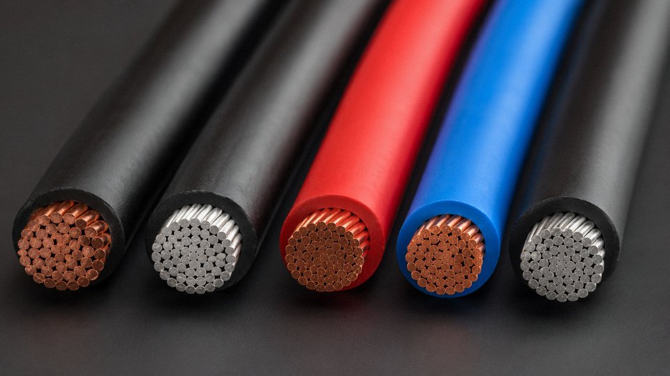
Aluminum is a different conversation. At roughly 61% IACS conductivity and a resistivity near 2.82 × 10⁻⁸ Ω·m, you need a larger cross-section to carry the same current — typically about 1.6× the copper area. For long distribution runs at 35 kV and above, that trade-off is economically rational. The problems show up at terminations: aluminum oxides quickly, the metal cold-flows under bolt pressure over time, and dissimilar-metal corrosion with copper lugs is a real maintenance headache. Every aluminum termination needs proper bi-metal connectors and anti-oxidant compound, without exception.
Copper-clad aluminum (CCA) sits in uncomfortable territory. It’s marketed as a cost compromise, but the conductivity is closer to aluminum than copper, and the lower tensile strength creates installation and termination problems that aren’t always obvious at the time of purchase. For anything carrying meaningful current or requiring flex life, CCA is a risk worth avoiding unless the application was specifically designed for it.
Insulation Polymer Families and What the Temperature Rating Actually Means
PVC is economical and globally available. Standard grades run from about −15°C to +70°C; heat-resistant HR-PVC grades extend that to +105°C. PVC softens under sustained mechanical load at high temperature and releases hydrogen chloride when it burns — a relevant limitation in enclosed or occupied spaces.
XLPE (cross-linked polyethylene) is the workhorse of medium- and high-voltage distribution. Cross-linking converts the thermoplastic PE into a thermoset structure that holds its geometry to +90°C continuous and survives short-circuit events up to around +250°C without catastrophic deformation. Moisture resistance is substantially better than PVC, and it doesn’t plasticize over time the way PVC can with plasticizer migration.
PTFE handles up to +260°C continuous and is chemically inert across nearly everything short of molten alkali metals. It’s the insulation you see on wiring inside industrial ovens, aerospace harnesses, and semiconductor fab equipment. The cost is high and it’s not trivially extrudable — machined or wrapped tape constructions are common.
TPE and TPU cover the flexible machinery cable space — Class 5 and Class 6 stranded conductors in robotic arms, drag chains, and food-processing lines where oil resistance and repeated flexing coexist. TPU in particular handles petroleum-based cutting fluids well, which PVC frankly doesn’t over a multi-year service life.
The temperature rating isn’t just a material property; it directly affects allowable ampacity under NEC Table 310.16. A 10 mm² conductor with XLPE insulation rated 90°C will carry meaningfully more current than the same conductor with 70°C PVC — the difference can run roughly 15–20% depending on ambient conditions and installation method. Undersizing because the engineer defaulted to the conservative insulation option costs money in copper; oversizing because someone ignored the 90°C rating is a code violation and a fire risk.
Jacket Materials and Fire Performance Standards
The outer jacket is often treated as mechanical protection only. It isn’t. In a tunnel, subway, or public building, jacket material governs how a fire behaves and how survivable the evacuation is.
PVC jacket covers general-purpose use — it’s cheap, durable against abrasion, and serviceable in most indoor environments. LSZH (low-smoke zero-halogen) compounds are mandatory in rail infrastructure, tunnels, airports, and many public buildings in Europe and increasingly in Asian markets. When PVC burns in an enclosed space, the HCl it releases is toxic at concentrations that arrive faster than visible smoke. LSZH compounds char rather than drip and produce dramatically less toxic gas — that’s not a marketing claim, it’s measurable under IEC 61034 (smoke density) and IEC 60754 (halogen content).
Polyurethane (PUR) jacket is the right answer for machine tools, welding cables, and anything exposed to hydraulic fluid, coolant, or sustained abrasion. It outlasts PVC in those environments by years. HDPE jacket is used for direct-burial and submarine cable where long-term water and soil chemical exposure matter more than flexibility.
Reading the compliance markings on a cable jacket tells you exactly what you’re getting — if you know the codes. A cable marked to IEC 60332-1 has passed single-cable vertical flame propagation. IEC 60332-3 covers bundled installation flame spread, which is a more demanding and more realistic test for cable trays. Both markings on the same reel mean meaningfully different things, and specifying the wrong one for a cable tray installation is a procurement error with potentially serious consequences.
Jinda operates in-house XLPE cross-linking lines and LSZH compounding facilities across its five production bases in China.True
Vertical integration of insulation compounding and cross-linking is a documented capability of established large-scale cable manufacturers; this capability provides material traceability, batch consistency, and eliminates the variability introduced by third-party compound suppliers — directly relevant for large international procurement contracts with strict material certification requirements.
Having XLPE cross-linking and LSZH compounding in-house rather than sourced from a third-party compounder means every production batch carries traceable material data back to the raw polymer input. For project engineers specifying cable to IEC 60840 or similar standards on large infrastructure contracts, that traceability isn’t optional — it’s what stands up during third-party inspection.
Frequently Asked Questions About Wire Types, Specifications, and Global Procurement
What is the difference between a wire and a cable?
A wire is a single electrical conductor — solid or stranded — with or without insulation over it. A cable is an assembly of two or more insulated wires, or sometimes a single conductor with additional protective layers, all bound in a common outer jacket. Simple enough in theory. In practice, procurement teams confuse the two constantly, and the consequences range from minor delays to receiving an entirely wrong product on-site. Specifying “single-core wire” when your installation requires a multi-core cable with an armored jacket is the kind of error that kills a project schedule. Get the terminology right in your purchase order, or at minimum verify with your supplier that they’ve interpreted your requirement correctly.
Can I substitute stranded wire for solid wire at the same AWG or mm² rating?
For ampacity purposes, yes — a 4 mm² stranded conductor carries the same current rating as a 4 mm² solid conductor under equivalent conditions. The complications are in the details. Terminal blocks and compression lugs designed for solid conductors may not grip stranded wire reliably; individual strands can work loose over time under vibration, which increases contact resistance and generates heat at the termination. Always check the connector manufacturer’s compatibility data. Also worth noting: stranded conductors sit at a marginally larger outer diameter than solid at the same cross-section, which matters for conduit fill calculations in dense raceways. Confirm the conductor class — Class 2 for fixed wiring, Class 5 or 6 for flexible applications — actually matches what the installation demands.
What does “5G-ready” mean for coaxial cable specifications?
Honestly, “5G-ready” is mostly marketing. Sub-6 GHz 5G deployments typically require 50 Ω low-loss coaxial cable — LMR-400 or a genuine equivalent — rated to at least 3 GHz with insertion loss under roughly 4 dB per 100 m at that frequency. mmWave 5G at 24–40 GHz is a different problem entirely: standard foamed-PE dielectric coax won’t cut it at those frequencies, and most installations at mmWave distances are short enough that foam-PTFE or air-spaced coaxial is used where fiber backhaul isn’t already the answer. When a supplier says “5G-ready,” ask for the actual attenuation curve versus frequency. If they can’t produce it, that tells you something.
How do I verify a wire manufacturer’s quality claims when sourcing internationally?
Third-party test reports from SGS, Intertek, or TÜV are the baseline — specifically covering conductor resistance, insulation resistance, voltage withstand, and dimensional tolerances against the declared standard. ISO 9001 certification is worth checking, but verify that the scope explicitly covers the product line you’re buying, not just a corporate entity. Factory audit rights matter more than paper certifications for large orders. Jinda supports customer factory audits across its five production bases and provides full test documentation as standard — not as a special request.
Jinda holds ISO 9001 certification covering its cable production operations across multiple manufacturing basesTrue
ISO 9001 scope verification is a standard procurement requirement; Jinda's certification covers its production facilities and quality management system applicable to its cable product lines.
What is the minimum bend radius for different wire types, and why does it matter?
Minimum bend radius is expressed as a multiple of the wire’s outer diameter (OD). Rough working figures:
| Wire Type | Minimum Bend Radius |
|---|---|
| Solid conductor (fixed install) | 8× OD |
| Flexible stranded (Class 5/6) | 4–6× OD |
| Coaxial (flexible type) | 10× OD |
| Cat 6A data cable | 8× OD |
Violating these limits deforms the conductor geometry in coaxial wire — which directly shifts impedance and causes reflections — and creates stress fracture initiation points in solid conductors. Insulation can crack at tight bends under thermal cycling even if it looks fine at installation. This is one of those failure modes that doesn’t show up immediately; it shows up 18 months later as an intermittent fault that’s expensive to trace.
Are there wire types specifically required for solar PV and wind energy installations?
Yes, and using standard wire in these applications is a genuine safety risk, not just a compliance issue. Solar DC circuits require USE-2 or UL 4703-listed PV wire in North American projects, or EN 50618 / TÜV 2PfG 1169-certified wire in European and international markets. The requirements — 90°C wet rating, UV-resistant jacket, double insulation for ungrounded systems — exist because rooftop and ground-mount DC strings run at high continuous voltage in outdoor exposure for 25+ years. Wind turbine tower cables are a separate category: they need high-torsion-flex Class 6 stranded conductors with oil-resistant TPU jackets rated to IEC 61400 environmental conditions, because the cable loop inside a rotating nacelle flexes continuously. Jinda supplies both product families for international renewable energy projects.
What are typical lead times and minimum order quantities for custom wire from a manufacturer like Jinda?
Standard catalog items from Jinda’s production bases generally ship within 15–30 days for volumes up to 50,000 meters, depending on current production scheduling and the specific product family. Custom specifications — non-standard conductor class, a particular insulation compound not in the standard lineup, bespoke jacket color coding for a national wiring code — add time: typically 30–45 days including tooling setup and first-article inspection sign-off. Minimum order quantities vary, but as a working reference, specialty wire starts around 500 meters and standard power wire around 2,000 meters. Consolidated orders across product types generally attract better pricing and simplify logistics, which is worth structuring into your procurement planning if you’re running a multi-phase project.
How to Write a Watertight Wire Specification for International Procurement: A Step-by-Step Protocol
Vague specs are expensive. A purchase order that says “4mm² copper cable, PVC insulated” gives a supplier room to deliver copper-clad aluminum (CCA) conductors, 60°C-rated insulation when you needed 70°C, and missing country approvals that will hold your shipment at customs for three weeks. The following protocol is written for engineers who have already been burned by at least one of those scenarios.

Step 1: Lock Down the Electrical Parameters First
Start with voltage rating in IEC notation — Uo/U, where Uo is the conductor-to-earth voltage and U is the conductor-to-conductor voltage. “300/500 V” and “0.6/1 kV” are not interchangeable; confusing them is a common mistake on projects transitioning from North American to IEC documentation. State maximum continuous operating current (ampacity) at the intended installation condition — in free air, in conduit, or buried — because the same 6 mm² conductor has meaningfully different ampacity in each. If your application runs above 50/60 Hz, call it out explicitly; drives and inverter outputs may reach 400 Hz or higher, and that changes dielectric loss and skin-effect heating in ways that surprise people who’ve only specified power-frequency cables. For instrumentation and control panel work, include the overvoltage category per IEC 61010 (CAT II, CAT III, or CAT IV). Omit it and you’ll get whatever the supplier stocks.
Step 2: Specify the Conductor So There’s No Wriggle Room
Write “annealed copper conductor per IEC 60228, Class 2 (stranded), cross-section 10 mm²” — not “10 AWG copper.” For IEC-regime projects, AWG creates ambiguity: 10 AWG is nominally 5.26 mm², not 6 mm², and a supplier reading an ambiguous spec will sometimes resolve the ambiguity in the direction that costs them less. State maximum DC resistance at 20°C per IEC 60228 Table 1 (for 10 mm² Class 2, that’s ≤1.83 Ω/km). That single number functionally prevents CCA substitution, because CCA at the same cross-section will fail the resistance check. IEC 60228 Class 5 (flexible) should be specified separately wherever flex life matters; Class 2 in a drag chain is a recipe for conductor fracture within months.
Specifying maximum DC resistance per IEC 60228 in the purchase order is the most reliable contractual lever to prevent copper-clad aluminum substitution.True
CCA conductors have roughly 1.5–1.7× the resistivity of solid copper, so a correctly specified IEC 60228 DC resistance limit is measurable, testable, and will catch CCA at incoming inspection or factory acceptance testing.
Step 3: Name the Insulation Standard and Temperature Class Explicitly
“PVC insulation per IEC 60227-2, Type A, 70°C rated” is enforceable. “Good quality PVC insulation” is not. Include color code requirements per IEC 60445: brown/black/gray for L1/L2/L3, blue for neutral, green-yellow for protective earth. If your destination country has a different convention (some older installations still use red/yellow/blue), say so and cite the local standard. Jacket material deserves the same treatment — distinguish between PVC, LSZH (Low Smoke Zero Halogen per IEC 60754), or XLPE as needed for the installation environment.
Step 4: List Required Approvals and Certification Type
CE marking for EU destinations, CCC for China, UL listing for North America, SAA for Australia. State whether self-declaration is acceptable or whether third-party certification from an accredited body is required. These are very different things; confusing them is surprisingly common on fast-moving infrastructure projects.
Step 5: Define Factory Acceptance Tests
Specify conductor resistance test, insulation resistance test, and high-voltage withstand test — including test voltage level and duration (e.g., 3.5 kV AC for 5 minutes for a 0.6/1 kV cable is a typical IEC 60227 requirement, though the exact value depends on the cable type and standard revision). State whether witnessed inspection by your own representative or a recognized third-party agency such as SGS or Bureau Veritas is required before goods leave the factory. If you skip witnessed FAT on large orders, you are trusting paperwork.
Step 6: Packaging, Marking, and Shipping Documents
Specify drum or reel size, sequential meter marking on the outer sheath at 1 m or 5 m intervals (critical for job-site cutting and leftover inventory tracking), and all required documentation: test certificates with actual measured values (not just pass/fail), packing list, certificate of origin, and MSDS for any chemical compounds in the cable materials. For EU-bound shipments, add REACH and RoHS compliance declarations — EU customs and end-client EHS teams will ask, and scrambling for them post-shipment wastes time.
Jinda’s technical sales team maintains pre-written IEC-compliant specification templates for the most common wire types — power, control, instrumentation, and data — which means procurement managers on large infrastructure projects aren’t starting from a blank page. That tends to compress the RFQ-to-confirmed-order timeline noticeably, particularly on projects where the buyer’s internal engineering team is already stretched.