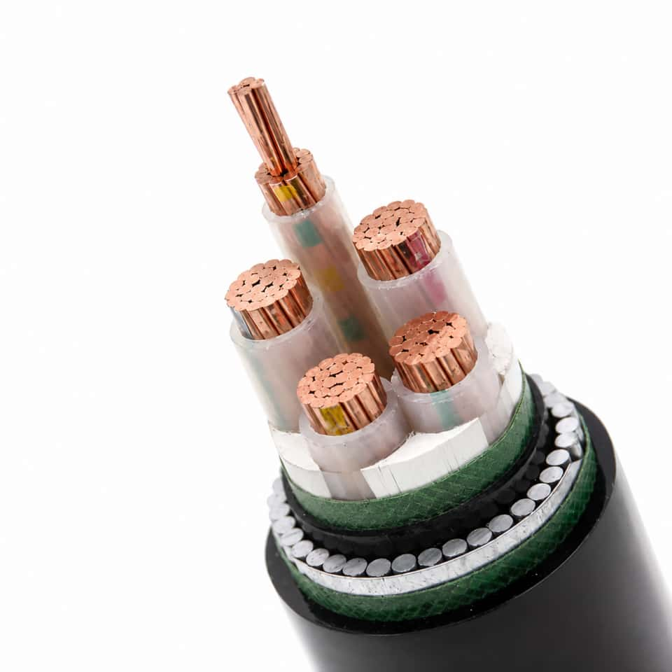
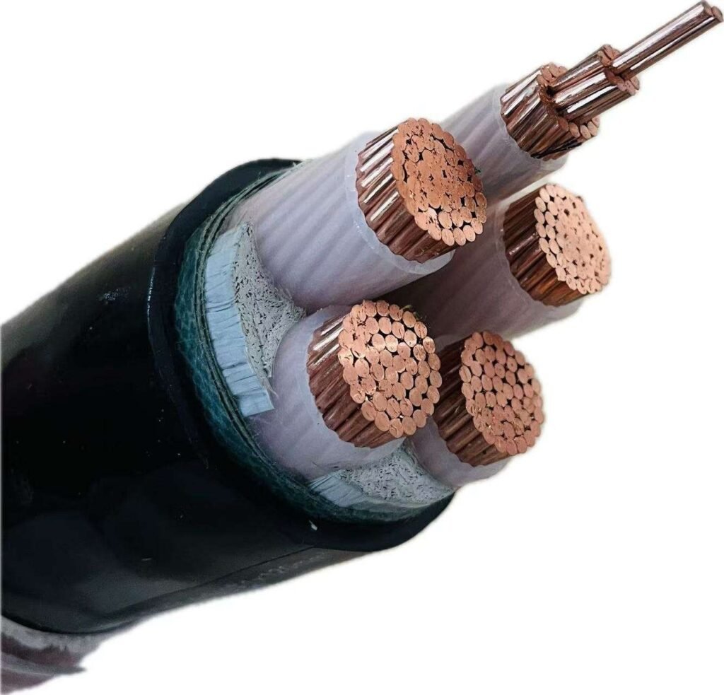
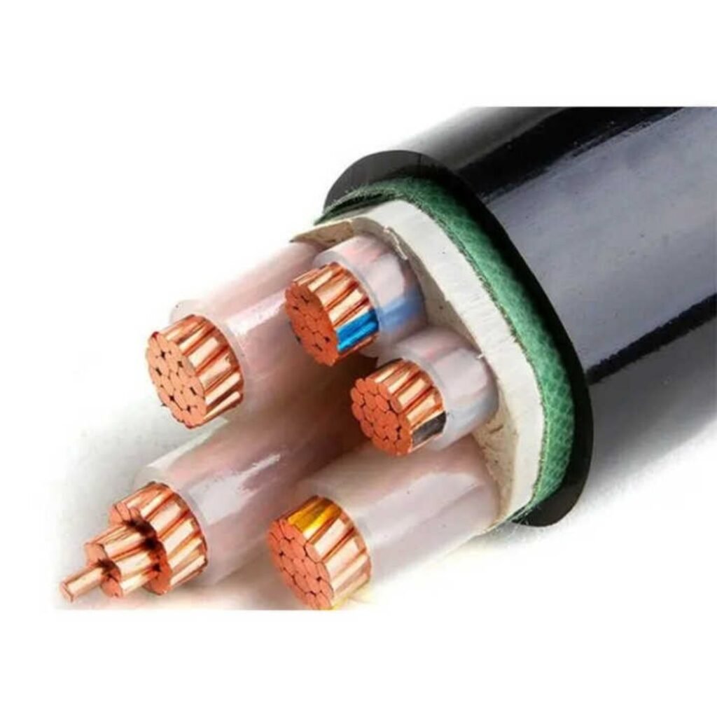
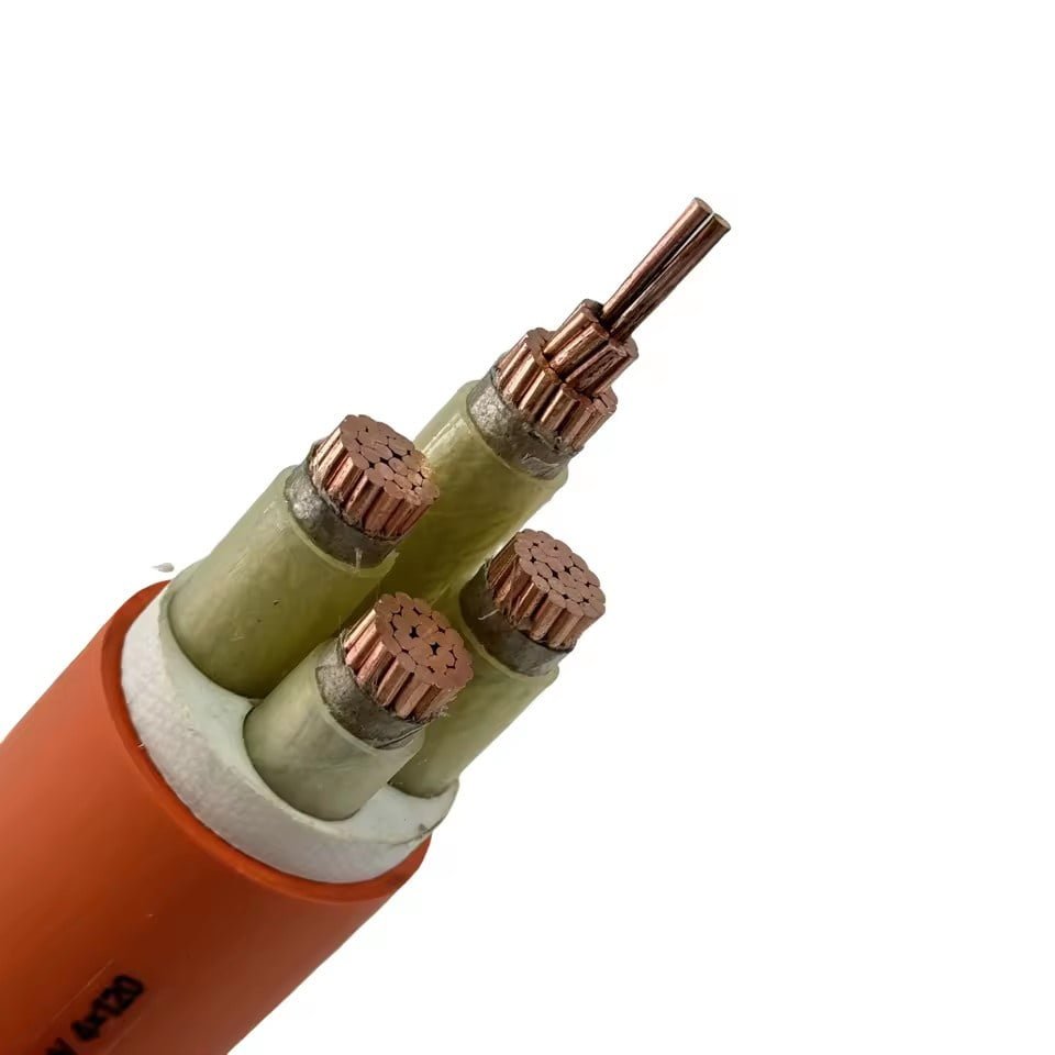
Mixing up cables and wires on a procurement order sounds like a minor clerical slip — until the wrong product shows up on-site, your electrician is looking at a single bare conductor where a multi-core assembly was spec’d, and the panel installation is sitting idle for two weeks waiting on a re-order. That delay has a real cost: expedited freight, contractor standby time, and in some production environments, lost throughput that dwarfs the original material spend several times over. Getting the terminology right at the specification stage is the cheapest fix available.
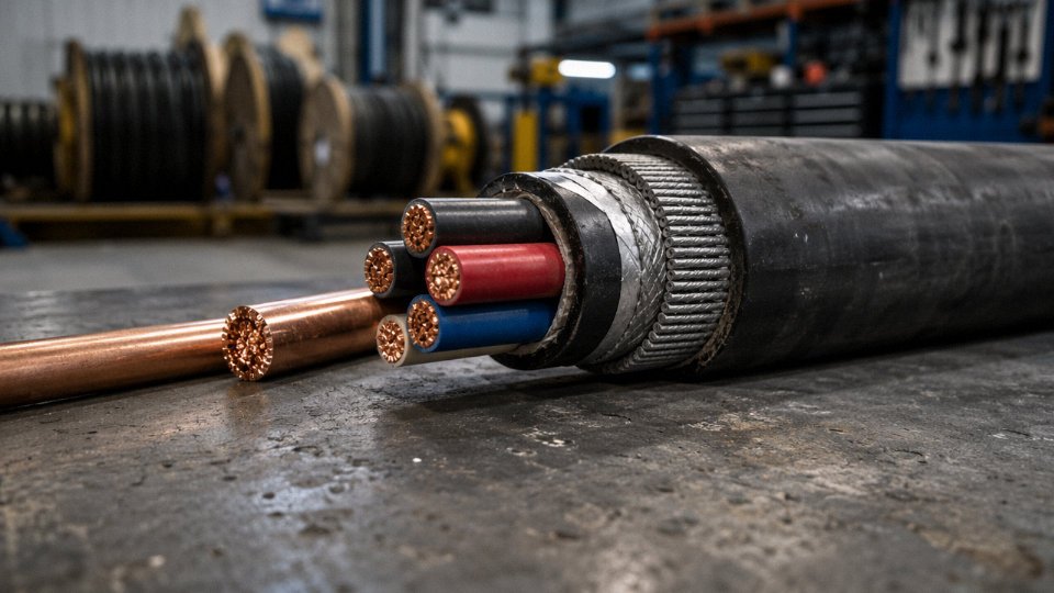
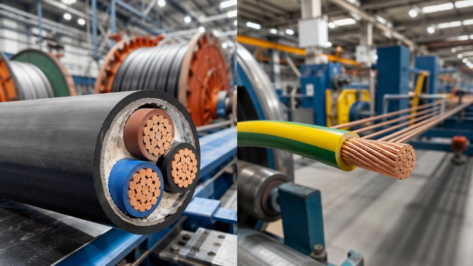
A wire is a single electrical conductor — solid or stranded — typically ranging from around 0.1 mm up to large cross-sections used in power transmission, and usually uninsulated or with only a basic jacket. A cable is an assembly of two or more insulated conductors (or one insulated conductor with a protective outer sheath), bundled and protected for a specific installation environment. The distinction determines mechanical rating, installation method, regulatory compliance, and ultimately whether the product is fit for purpose.
What makes this worth unpacking properly is that the line between the two isn’t always clean in practice. Trade usage varies by country, application, and even decade — a “wire” on a North American electrical drawing often means something a European procurement manager would call a cable, and vice versa. The insulation system alone can shift a product from one category to another depending on the standard you’re working to, and with the global wire and cable market sitting somewhere north of USD 225 billion and heading toward USD 300 billion by 2030, the volume of misspecified product moving around the world at any given moment is not trivial.
Exact Technical Definitions: What Makes a Wire a Wire and a Cable a Cable
The word “wire” appears in IEC 60228, the core international standard for conductors of insulated cables. There, a wire is defined functionally as a single conductor — solid or stranded — of copper or aluminum (or occasionally aluminum alloy), with or without insulation. That’s it. One conductor. The cross-section can range from as fine as 0.1 mm² for instrumentation work up through 630 mm² or larger for power transmission, and whether it carries insulation or not doesn’t change its classification as a wire. NEC Article 100 stays consistent with this: a conductor is described as a material, usually in the form of a wire, suitable for carrying electric current, and the “wire” designation implies a single conductive element.
A cable is a different animal. IEC 60502 — which governs power cables with extruded insulation for voltages from 1 kV up to 30 kV — defines a cable as an assembly of one or more insulated conductors, collectively enclosed within an outer sheath, armor, or protective jacket. BS 7671 (the UK’s IET Wiring Regulations, 18th Edition) uses similar language, emphasizing the outer enclosure as the thing that makes an assembly a cable. The critical word is assembly. Strip away the outer sheath and you’re left with wires, not a cable.
This distinction matters in practice more than most people realize at the purchase-order stage.
Where the Definitions Get Complicated
A few edge cases trip up even experienced engineers. Twin-and-earth domestic wiring — the flat grey stuff running behind UK plasterboard walls — is universally called a cable and governed under BS 7671, yet its electrical topology has only one live conductor plus a neutral and an uninsulated CPC (circuit protective conductor) grouped inside a flat PVC sheath. By strict count it seems ambiguous, but the outer sheath enclosing all three elements is what puts it squarely in the “cable” category.
Coaxial cable is another one. There’s arguably a single signal conductor at the center, but the coaxial construction — center conductor, dielectric, foil or braid shield, outer jacket — is an engineered assembly designed for controlled impedance and EMI screening. The outer protective and functional assembly defines it as a cable, full stop.
Mineral-insulated copper-clad (MICC) cable, sometimes still called by the old Pyrotenax brand name on older plant drawings, is the most extreme case. It’s a copper conductor packed in compacted magnesium oxide inside a seamless copper sheath — no conventional insulation in the polymer sense. Yet it’s a cable by every applicable standard, because the outer metallic sheath forms the protective enclosure. The defining attribute is consistently the outer assembly, not the insulation type or conductor count.
Wire vs. Cable: Comparison at a Glance
| Attribute | Wire | Cable |
|---|---|---|
| Number of conductors | Single (solid or stranded) | One or more, assembled |
| Outer protection | None, or basic insulation only | Collective sheath, armor, or jacket |
| Flexibility | Varies: solid is rigid, fine-stranded is highly flexible | Depends on construction; armored cables are stiff |
| Typical cross-section range | 0.1 mm² up to 750 mm² and beyond | 1.5 mm² twin-and-earth to 1,000 mm² power cable |
| Primary governing standard | IEC 60228, NEC Article 100 | IEC 60502, BS 7671 |
| Typical voltage class | Low voltage (building wire, hookup wire) | LV through HV depending on insulation grade |
The Colloquial Trap
On the plant floor and in contracting, people routinely say “wire the panel,” “run the wire to the junction box,” or “how much wire do you need?” — meaning any cable run, regardless of construction. This is so common that even experienced electricians use “wire” and “cable” interchangeably in conversation.
The problem surfaces when that loose language migrates into purchase orders or RFQs. A procurement spec that says “supply 2-core wire, 2.5 mm², 100 m” could be interpreted by a supplier as unsheathed twin conductor rather than the sheathed 2-core cable the engineer actually intended. In a worst case, you receive unsheathed conductor that fails the installation’s mechanical protection requirements, triggering a rejection, a reorder lead time, and an installation delay. The fix is simple but needs discipline: use the IEC or NEC designation in every written specification, not the colloquial shorthand.
IEC 60228 defines a wire as a single conductor, solid or stranded, with or without insulationTrue
IEC 60228 is the IEC standard for conductors of insulated cables and explicitly addresses individual conductors in both solid and stranded form, copper and aluminum, which aligns with the definition stated here.
Conductor Construction: Solid, Stranded, and Bunched — How the Core Affects Performance
The conductor is where most specification mistakes actually happen. Installers sometimes order flexible stranded cable for a fixed conduit run because it “feels more robust,” or specify solid conductors for a machine tool application where the cable bends on every cycle. Both choices cost money — either in unnecessary material expense or, worse, in premature conductor fatigue and unplanned downtime six months into production.
Solid Conductors: Simple, Cheap, and Right for the Right Job
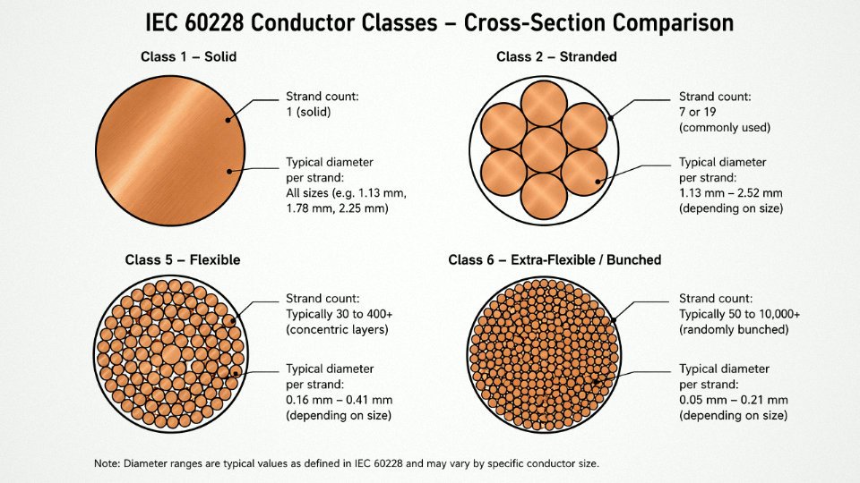
A solid conductor is exactly what it sounds like — a single drawn rod of copper or aluminum, no strands, no lay length to worry about. Per IEC 60228 Class 1, this is the standard for fixed wiring in buildings and infrastructure. In practice, solid copper works well up to around 16 mm² in conduit or trunking installations; above that, the rigidity makes termination genuinely awkward and increases the risk of nicking the conductor when stripping insulation. Electricians know this — you’ll often see 25 mm² and above supplied stranded even in fixed installations just for handling reasons.
Cost advantage is real but conditional. Solid conductors are slightly cheaper to produce, and for a large building project with kilometers of 2.5 mm² or 4 mm² branch circuit wiring, that difference adds up. Don’t dismiss it.
Stranded Conductors: Lay Length, Flexibility, and Fatigue Life
Stranded conductors are built from multiple individual wires twisted together in one or more concentric layers. The critical variable most buyers ignore is lay length — the axial distance over which each strand completes one full helical revolution. Shorter lay length means tighter twist, which distributes bending stress more evenly across individual wires and improves both flexibility and fatigue resistance. This matters enormously in moving applications.
IEC 60228 defines the classes that actually map to application:
Class 2 uses a relatively open lay and is designed for fixed power cables. You’ll find it in most industrial power distribution cables, armored cables for buried runs, and medium-voltage feeders. It handles termination well and is compatible with most compression lugs without modification.
Class 5 tightens the stranding considerably and is the standard for flexible cords — think trailing leads, portable tools, and control cables on panel doors that open and close periodically. The individual wire diameters are smaller (often 0.2–0.4 mm per strand depending on overall cross-section), and the increased strand count distributes flex stress over more wires.
Class 6 goes further still, with even finer individual wires and sometimes a bunched rather than concentric lay geometry. This is the class for continuous-flex applications: robot arm cables, drag chain wiring, festoon systems. A cable seeing tens of millions of flex cycles at bend radii of 5–7× cable diameter needs Class 6 — and still needs a purpose-designed TPE or special PVC jacket compound, not standard PVC. Specifying Class 5 here is a common error; it’ll work for months, then start breaking individual strands internally with no visible external damage until the resistance climbs and something gets hot.
Copper vs. Aluminum: The Conductivity and Termination Trade-off
Copper sits at roughly 58 MS/m conductivity; aluminum at around 35 MS/m. That gap means an aluminum conductor needs to be approximately 1.6× the cross-section of copper to carry the same current — so a 95 mm² aluminum conductor is roughly equivalent to 70 mm² copper in ampacity terms, depending on installation method and ambient temperature.
Aluminum’s real advantages are weight and cost. For long overhead distribution runs or large cable trays carrying 240 mm² and above, the weight reduction is significant and the material cost difference is substantial. The operational penalty is at terminations: aluminum oxide forms quickly on a bare surface, increasing contact resistance and generating heat. Every aluminum termination needs anti-oxidant compound applied and a correctly rated aluminum-compatible lug. Skip the compound and you’re looking at a warm joint that works fine for a year and fails at peak load on the hottest day of summer.
Aluminum conductors require larger cross-sections than copper to carry equivalent current due to aluminum's lower electrical conductivity.True
Copper conductivity is approximately 58 MS/m versus aluminum's approximately 35 MS/m — roughly a 1.6:1 ratio — requiring proportionally larger aluminum cross-sections to achieve equivalent current-carrying capacity at the same temperature rise.
Current-Carrying Capacity Reference: Copper, XLPE 90°C, Free Air
These figures follow IEC 60364 / IEC 60502 guidance for single-circuit installation in free air at 30°C ambient. Actual capacity varies with grouping, burial depth, ambient temperature, and installation method — always run a derating calculation for real projects.
| Conductor Cross-Section | Approx. Current Capacity (A) | Practical Application Context |
|---|---|---|
| 1.5 mm² | 22–26 A | Lighting circuits, control wiring |
| 2.5 mm² | 30–36 A | Branch circuits, small motor feeders |
| 4 mm² | 40–46 A | Motor feeders, socket circuits |
| 6 mm² | 52–60 A | Medium motor feeders |
| 10 mm² | 70–80 A | Sub-distribution, larger motors |
| 16 mm² | 90–105 A | Sub-main feeders |
| 25 mm² | 120–135 A | Panel feeders, larger machinery |
| 35 mm² | 145–165 A | Distribution boards |
| 50 mm² | 170–195 A | Main feeders, MCC incomer |
| 70 mm² | 210–240 A | Heavy industrial feeders |
| 95 mm² | 250–285 A | Large motor feeders, transformer tails |
| 120 mm² | 285–325 A | Main distribution |
| 150 mm² | 320–365 A | High-current distribution |
| 185 mm² | 360–415 A | Main incomer cables |
| 240 mm² | 415–475 A | LV transformer secondaries |
| 300 mm² | 465–535 A | Heavy bus feed |
| 400 mm² | 530–610 A | Substation feeders |
| 630 mm² | 660–755 A | Main HV/LV interface feeders |
Ranges reflect variation in installation conditions. A 95 mm² cable clipped directly to a hot cable tray in a 45°C plant will sit at the low end; the same cable in open free air at 25°C ambient will exceed the upper end.
Insulation and Jacket Materials: PVC, XLPE, EPR, LSZH, and When to Choose Each
Insulation is not a commodity decision. Specifying the wrong material might not cause an immediate failure — it usually shows up six months later as premature cracking in a cold-storage facility, or as a fire that spreads faster than it should have because the building used PVC-jacketed cables in a congested cable tray above an occupied floor. The material choice drives temperature headroom, chemical compatibility, smoke toxicity, and ultimately how long the installation actually lasts under real operating conditions.
PVC — The Workhorse With a Known Weakness
Polyvinyl chloride is the default for general-purpose indoor wiring, and there’s a reason it’s dominated the market for decades: it’s cheap, it processes easily, it handles moisture well, and it meets IEC 60502-1 for fixed indoor installations without any exotic additives. Conductor temperature rating sits at 70°C continuous, which is adequate for most building wiring loaded at code-permitted ampacity.
The problem is fire behavior. PVC releases hydrogen chloride gas when it burns. In an enclosed plant or office building, that gas is corrosive to electronics and toxic to people — and it keeps generating long after the flame source is gone. I’ve seen post-fire damage assessments where the cable itself barely charred, but the HCl off-gassing corroded a switchboard two rooms away. For open industrial floors with good ventilation and no public occupancy, PVC is often still the practical choice. For anything with confined cable routes, that calculation changes.
XLPE — The Right Answer for Medium and High Voltage
Cross-linked polyethylene is thermosetting, meaning once cured, the polymer network won’t soften the way PVC does under heat. That gives you 90°C continuous and short-circuit withstand temperatures up to around 250°C — critical for MV cables per IEC 60502-2 and HV cables per IEC 60840. Dielectric strength is superior to PVC, water treeing resistance is better (particularly important in direct-buried MV runs), and you get meaningfully higher current-carrying capacity for a given conductor cross-section compared to an equivalent PVC-insulated cable.
The trade-off is that XLPE is stiffer, especially in cold weather, and installation crews need to respect minimum bending radii more carefully. Cutting corners there causes micro-cracks that won’t show up until the cable has been energized under load cycling for a year or two.
XLPE-insulated cables rated to IEC 60502-2 can sustain short-circuit temperatures up to 250°C at the conductor.True
Cross-linked polyethylene is thermosetting and retains structural integrity at conductor temperatures up to approximately 250°C during short-circuit conditions, as specified in IEC 60502-2 and supported by standard cable design calculations.
EPR — Cold Environments and Mobile Applications
Ethylene propylene rubber stays flexible down to around -40°C, which makes it the insulation of choice for offshore platform trailing cables, mining draglines, and any mobile equipment that gets dragged across cold ground repeatedly. It also handles ozone and UV exposure better than most alternatives — relevant on topside offshore installations where cables see direct sunlight and salt-laden air simultaneously. Continuous rating matches XLPE at 90°C, but the flexibility advantage is the real reason to pay the premium. If your cable doesn’t flex in service, EPR’s main benefit evaporates.
LSZH — Non-Negotiable in Occupied Public Spaces
Low smoke zero halogen compound is mandatory — not a preference — in rail tunnels, metro systems, public buildings, marine vessel interiors, and data centers where evacuation routes can become filled with smoke quickly. IEC 60332 and EN 50575 define the flame propagation and smoke emission limits that drive this requirement. The material produces minimal smoke and no halogen acid gases, giving occupants survivable conditions for longer during a fire event.
LSZH does cost more than PVC — typically 20–40% more on the cable unit price, depending on conductor size and sheath thickness — and it’s moderately less abrasion-resistant in rough-handling environments. Some contractors try to avoid it on cost grounds in applications where it’s required by the building code or project specification. That’s a procurement decision that creates liability, not savings.
Silicone Rubber — High-Temperature Niche
Silicone cable insulation handles 180°C or higher continuously, which puts it in a different class from everything else listed here. Furnace wiring, kiln sensor leads, aerospace harnesses, automotive under-hood applications — anywhere ambient temperatures alone would cook a standard cable. The mechanical properties are the limitation: silicone tears and abrades easily, so it almost always needs a braided or armored outer protection in industrial settings. Cost is substantially higher, and it’s not a general-purpose substitute for XLPE just because you want more thermal margin.
Matching Material to Conditions — A Working Decision Matrix
| Application Environment | Recommended Insulation | Recommended Outer Sheath | Key Standard |
|---|---|---|---|
| Indoor fixed wiring, dry | PVC | PVC | IEC 60502-1 |
| Outdoor direct burial, MV | XLPE | PE or HDPE with armoring | IEC 60502-2 |
| Underwater / submarine | XLPE or EPR | Lead sheath + PE oversheath | IEC 60840 |
| Fire-risk zone, public building | LSZH | LSZH | IEC 60332, EN 50575 |
| High-flex, mobile, offshore | EPR | CPE or PUR | — |
| High-temperature fixed (>130°C ambient) | Silicone rubber | Silicone or braided glass fiber | — |
The matrix above is a starting point, not a final specification. Actual sheath selection also depends on chemical exposure (hydraulic oils will attack PVC sheaths faster than most engineers expect), rodent risk, UV exposure duration, and whether the installation is direct burial or conduit. Get the application environment wrong, and no conductor sizing calculation saves you.
Cable Construction Layers: Armor, Screens, Fillers, and Bedding — What Each Layer Does
Crack open a datasheet for a medium-voltage power cable and you’ll see a list of layers that can run eight or nine items deep. Most procurement managers skim past them. That’s where specification errors happen — someone orders a cable with steel tape armor when the route includes a 40-meter vertical riser, or they strip off a semiconducting screen during termination without understanding what it actually does. Walking through these layers one by one is worth the time.
Conductor Screen
In any cable rated above roughly 3.3 kV, you’ll find a layer of semiconducting material — either an extruded compound or a wrapped tape — sitting directly against the conductor surface. Its job is field equalization. A stranded conductor has irregular geometry: air gaps between strands, micro-points where the electric field wants to concentrate. Without a conductor screen, those stress concentrations initiate partial discharge, which silently erodes the insulation over months or years before you ever see a fault. The semiconducting layer smooths the field into a controlled, radial distribution. This is not optional in MV and HV cables — IEC 60502-2 requires it above 6 kV.
Insulation Screen
A second semiconducting layer sits on the outside of the main insulation, and it’s equally critical at terminations. When you cut and terminate an MV cable, voltage grading at the cut edge is the weak point. The insulation screen gives termination accessories — stress cones, heat-shrink kits, cold-shrink systems — a defined interface to work against. Removing it carelessly, or cutting it at the wrong point, is one of the most common causes of premature termination failure in the field. Some contractors treat it as tape to be discarded. It isn’t.
Metallic Screen or Shield
Copper tape, copper wire braid, or aluminum foil wound over the insulated cores serves two distinct purposes depending on the application. In power cables it carries fault current back to the source — the cross-sectional area of the screen determines the fault current rating, typically sized for 1-second fault withstand. Coverage percentage matters: a 100% overlap copper tape screen performs differently from a 25%-overlap braid, which may suit EMI shielding in a control cable but would be entirely inadequate as a fault return path. For signal and instrumentation cables, the screen’s primary function is EMI rejection, and a braid coverage below about 85–90% starts to show measurable degradation in high-frequency shielding effectiveness.
Bedding (Inner Sheath)
Between the metallic screen and the armor sits a layer of extruded PVC or PE. Thin, often overlooked, genuinely important. It stops the armor wires from abrading directly against the screen or insulated cores during flexing and thermal cycling. It also provides a modest moisture barrier and acts as a cushion that prevents armor wire indentation under crush loads. Skipping a proper bedding spec on a cable that will be direct-buried in rocky ground is a slow path to insulation damage.
Armor
This is where the structural protection lives, and the choice of armor type is not interchangeable.
| Armor Type | Best For | Watch Out For |
|---|---|---|
| Steel Wire Armor (SWA) | Direct burial, vertical risers, tensile loads | Heavy; not for single-core AC — eddy currents |
| Steel Tape Armor (STA) | Crush resistance, horizontal direct burial | Low tensile strength; poor for vertical runs |
| Aluminum Wire Armor (AWA) | Single-core cables, weight-sensitive installs | Lower tensile strength than SWA |
| Wire Braid Armor | Flexible cables, repeated movement | Not suited to static direct burial |
A cable in a vertical shaft carrying its own weight over 30+ meters needs SWA with sufficient wire cross-section — undersizing it is the kind of error that shows up as a dropped cable two years into operation.
Outer Sheath
The final layer is the cable’s face to the world. Material selection here is driven by the installation environment: standard black PVC for most indoor and buried applications, orange-sheathed HDPE or PVC for underground utility routes where excavation warning is required, red outer sheath coding used in some fire-resistant system standards. If the route runs through oil-contaminated areas, a nitrile-modified sheath or LSZH compound may be necessary — standard PVC softens and swells in prolonged hydrocarbon contact. UV resistance matters for exposed outdoor runs, and in practice a cable left on a roof penetration for several years without UV-stabilized compound will show surface cracking well before its rated life.
In medium-voltage cables above 6 kV, both conductor screen and insulation screen are mandatory under IEC 60502-2 and cannot be omitted or substituted without impacting partial discharge performance and termination integrity.True
IEC 60502-2 specifies semiconducting conductor and insulation screens as required construction elements for cables in the 6 kV to 30 kV range, directly linked to partial discharge limits and termination compatibility requirements in the same standard.
Reading a cable datasheet layer by layer, rather than stopping at conductor size and voltage rating, is what separates a specification that survives commissioning from one that generates warranty claims eighteen months later.
Application Mapping: Which Wire or Cable Type Belongs in Which Installation Environment
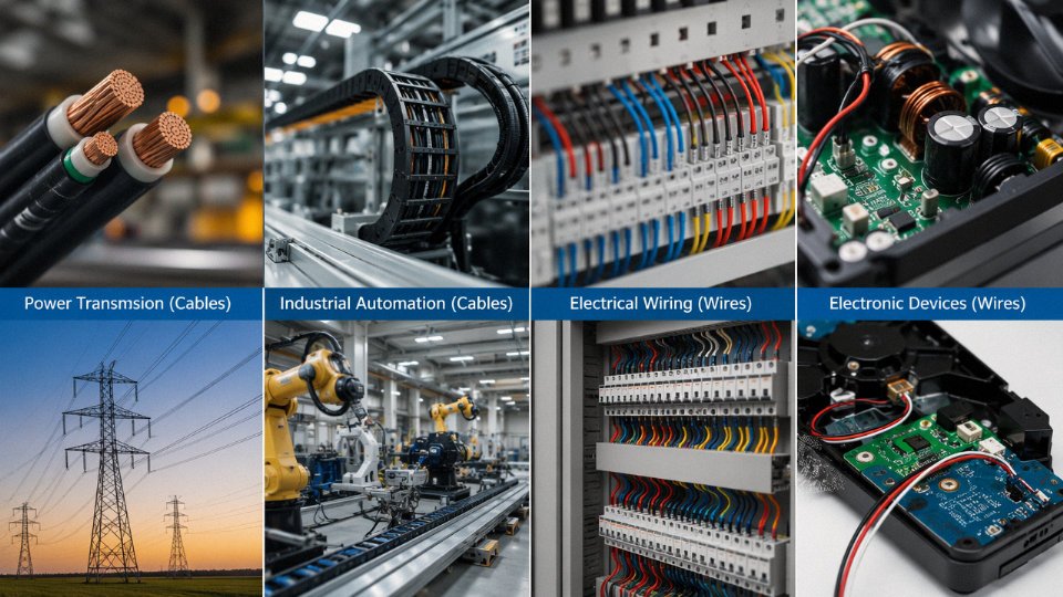
Getting the definition right is only half the battle. The real specification work starts when you have to match a product to a specific installation environment — and that’s where a lot of procurement errors happen. A project manager who specifies a standard NYY cable for a solar farm DC string circuit, or uses a screened instrumentation cable where a fieldbus cable with defined impedance is required, will find out the hard way during commissioning or, worse, during the first summer of operation.
Low-Voltage Building Wiring (Up to 1 kV)
For fixed building installations, NYY (PVC insulated, PVC sheathed) and N2XY (XLPE insulated, PVC sheathed) are the workhorses across most IEC-aligned markets. NYY handles the majority of conduit and ducted runs; N2XY is the better call for direct burial because XLPE handles soil moisture and cyclic thermal loading better than PVC over a 25–30 year service life. Single-core versions work fine in conduit where you’re pulling phases separately. Multi-core — typically 3- or 4-core — simplifies trench work and reduces installation labor when current demand is moderate, say under 150–200 A depending on conductor cross-section and soil thermal resistivity. IEC 60502-1 is the governing standard here. One practical note: in hot climates where ground temperatures run above 30°C, you need to derate conductor ampacity — something PVC-insulated cables feel more acutely than XLPE given the 70°C vs 90°C continuous rating difference.
Medium-Voltage Distribution (1 kV to 36 kV)
At medium voltage, XLPE-insulated armored cables dominate — covered under IEC 60502-2. The choice between single-core and three-core is mostly a function of current magnitude and how you’re laying the cable. Three-core designs in trefoil are compact, easier to handle on smaller projects, and inherently balanced, which is why they’re preferred for 11 kV feeder runs in the 95–240 mm² conductor range. Once you push into larger cross-sections — 300 mm² and above — single-core cables in trefoil formation usually make more sense because the per-core weight and bending radius of a three-core at that size become awkward to manage in the trench or on cable trays. Aluminum conductors are common at this voltage class in cost-sensitive infrastructure projects; copper tends to appear where space is tight or where corrosion exposure makes aluminum terminations problematic.
Industrial Control and Instrumentation
This is where screening choices matter most, and where under-specifying costs you in signal quality rather than immediate failure. Analog 4–20 mA loops can tolerate a single overall screen tied to ground at one end. Once you’re running multiple analog pairs in the same cable, individual pair screening plus an overall screen (the “OS+IS” configuration) is worth the price premium — crosstalk between pairs in a noisy drive environment is a real and recurring problem. For digital fieldbus — PROFIBUS, Foundation Fieldbus, CANopen — cable impedance matching is non-negotiable. IEC 61158 defines the cable types by fieldbus protocol, and substituting a generic screened cable because it’s cheaper will introduce reflections that look like intermittent faults and take days to diagnose.
Renewable Energy
Solar PV: Single-core DC cables for string and combiner wiring need a 1.5 kV DC voltage rating, not just AC rating — the distinction matters because DC arc faults are more sustained than AC. UV-resistant LSZH or XLPE jackets are the standard expectation; look for TÜV 2 Pfg 1169 or IEC 62930 approval on the datasheet. In desert installations, surface temperatures on cable trays can reach 70–80°C ambient before you account for current-generated heat, so conductor sizing should not be taken straight off a standard ampacity table.
Wind turbines: The torsion-flex cables running from the nacelle down the tower are a different animal entirely. They’re rated for continuous torsional flexing — 10 million cycles is the typical design target — using fine-stranded copper conductors and specially formulated rubber compounds. Standard power cable simply fatigues and fails within a few years in this application.
Marine and Offshore
IEC 60092 series governs shipboard cable, and the requirements reflect the environment honestly: halogen-free sheathing, oil and mud resistance, and flame propagation performance per IEC 60332-3. The distinction between shipboard cable and submarine cable sometimes confuses buyers. Shipboard cable is designed for routing through a vessel’s structure — bulkheads, engine rooms, deck areas — with mechanical protection from armor or heavy sheath but no requirement for seawater immersion over its entire length. Submarine cable is an entirely different product: designed for continuous seawater immersion at pressure, with water-blocking layers, heavy wire armor for mechanical protection against anchors or seabed contact, and lead or copper moisture barriers in some designs.
Mining
Trailing cables and reeling cables in mining face a combination of hazards that’s hard to match elsewhere: continuous flexing, crushing under vehicle traffic, hydrocarbon contamination, and sometimes explosive atmosphere requirements. EPR insulation is strongly preferred here — it maintains flexibility and dielectric integrity across the -40°C to +90°C temperature swings that underground and surface mining environments can produce. Heavy-duty rubber sheaths rather than PVC are specified precisely because PVC stiffens in cold temperatures and becomes brittle under repeated mechanical stress. IEC 60502 and IEC 62219 both apply depending on configuration, and mining cables typically require third-party certification rather than self-declaration.
EPR insulation maintains superior flexibility and electrical performance compared to PVC in mining trailing cable applications subject to continuous flexing and chemical exposure.True
EPR (ethylene propylene rubber) has a continuous operating temperature rating of up to 90°C and retains flexibility at low temperatures where PVC becomes brittle, making it the industry-standard insulation for mining trailing and reeling cables per IEC 62219.
Summary: Application-to-Cable Selection Reference
| Application Sector | Recommended Cable Type | Voltage Class | Insulation Material | Armor Type | Key Standard |
|---|---|---|---|---|---|
| Building wiring | NYY / N2XY | Up to 1 kV | PVC / XLPE | SWA or unarmored | IEC 60502-1 |
| MV distribution | XLPE armored, 3-core or single-core | 1 kV – 36 kV | XLPE | SWA / AWA | IEC 60502-2 |
| Industrial control | Multi-pair screened | Up to 1 kV | PVC / LSZH | Unarmored or braided | IEC 61158 |
| Solar PV DC | Single-core DC solar cable | 1.5 kV DC | XLPE / LSZH | Unarmored | IEC 62930 / TÜV 2 Pfg 1169 |
| Wind turbine | Torsion-flex power cable | Up to 1 kV | Rubber / XLPE | Unarmored flex | IEC 60502-1 + flex rating |
| Marine / shipboard | Halogen-free marine cable | Up to 1 kV | XLPE / EPR | Braided or unarmored | IEC 60092 |
| Mining trailing | Trailing / reeling cable | Up to 3.3 kV | EPR | Heavy rubber sheath | IEC 62219 |
How to Read a Cable Specification and Purchase Order Correctly: Avoiding the 10 Most Common Errors
Procurement errors on cable orders are rarely caught until installation — sometimes not until a fault occurs. Here are the ten mistakes that show up repeatedly on real projects, along with what to do instead.
Error 1 — Omitting Voltage Class
Always write rated voltage as Uo/U: 0.6/1 kV, 3.6/6 kV, 6/10 kV. The Uo value (conductor-to-earth) directly controls insulation wall thickness in the design. Specifying “1,000 V nominal” without the Uo/U designation leaves the manufacturer guessing, and some will default to a lower insulation grade. On a medium-voltage project, that’s not a paperwork problem — it’s a latent dielectric failure waiting to happen.
Error 2 — Confusing Conductor Cross-Section With Cable Outer Diameter
A 95 mm² cable is absolutely not 95 mm in diameter. The cross-section figure describes the conductor area; overall cable OD depends on conductor count, insulation thickness, armor type, and jacket. As a rough working reference:
| Conductor Size | Approx. OD (3-core armored, PVC/PVC) |
|---|---|
| 16 mm² | ~22–26 mm |
| 50 mm² | ~38–44 mm |
| 95 mm² | ~52–60 mm |
| 240 mm² | ~74–85 mm |
OD ranges depend on armor wire gauge, bedding thickness, and whether a screen is included. Always request the actual dimensional drawing before sizing conduits or cable trays.
Error 3 — Ordering “Flexible” Cable Without Specifying Flex Class or Cycle Count
IEC 60228 Class 5 covers fine-stranded conductors rated for occasional flexing. For a robotic tether or a drag-chain application running thousands of cycles per day, you need Class 6 or a purpose-built continuous-flex construction — different wire gauge, different lay length, sometimes a different insulation compound entirely. Class 5 in a continuous-flex installation will show conductor fatigue breaks within months, sometimes weeks in aggressive duty cycles.
Error 4 — Ignoring Ambient Temperature Correction Factors
IEC 60364-5-52 current ratings assume 30°C ambient. In a plant where cable trays run above a furnace or through an engine room sitting at 45–55°C, derating is mandatory. Depending on insulation type and actual ambient, you may need to upsize one or even two cross-section steps. This is especially easy to overlook when the cable is specified by an office engineer who has never stood in that part of the plant in July.
Error 5 — Substituting Aluminum for Copper Without Recalculating
Aluminum carries roughly 60–65% of copper’s current per unit area, so you need approximately 1.5–1.6× the cross-section for equivalent capacity. A direct substitution of 95 mm² aluminum for 95 mm² copper on a feeder circuit will result in a cable running hot — and that affects termination hardware, conduit fill, and voltage drop calculations too. The substitution can be perfectly valid, but only after the numbers are re-run.
Aluminum conductors require approximately 1.5–1.6× the cross-section of copper to carry equivalent current.True
This is consistent with the conductivity ratio of aluminum (~35 MS/m) versus copper (~58 MS/m), and is the standard basis for aluminum conductor sizing per IEC and NEC guidelines.
Error 6 — Overlooking Short-Circuit Current Rating
The cable screen and armor need to survive the maximum prospective fault current for the fault clearance time of the upstream protective device. Specify both figures on the PO. Undersized armor wires or screens can rupture during a fault, turning a recoverable event into physical cable destruction.
Error 7 — Not Specifying Drum Length vs Cut Length Tolerance
Standard drum lengths carry an IEC-permitted length tolerance of roughly ±5%. On a large order that can mean tens of meters of surplus or shortfall. If your project has tight pulls with exact meterage, specify cut lengths explicitly and state the tolerance you’ll accept — usually ±1% is achievable at a small premium.
Error 8 — Missing Fire Performance Class
“Fire-resistant cable” without a class designation means nothing useful on a purchase order. EN 50575 defines Aca through Fca classes with specific flame spread, heat release, smoke, and acidity criteria. Cca-s1b-d1-a1 and Eca are not interchangeable for a public building or transit application. Write the class on the spec sheet.
Error 9 — Accepting Test Certificates for a Different Cable Construction
This one burns people regularly. A supplier submits a perfectly legitimate third-party test report — but for a 70 mm² XLPE cable when you ordered 95 mm² PVC/SWA/PVC. Always verify that the submitted certificate matches conductor size, insulation material, armor type, and voltage class exactly. A certificate for a related product is not compliance for your product.
Error 10 — Ignoring Minimum Bending Radius
Exceeding bending radius during a cable pull can crack insulation or deform armor, and the damage may not be immediately visible. As a general rule, minimum installation bending radius runs from about 6×OD for lightly armored control cables up to 20×OD for large steel-wire-armored power cables, with exact figures depending on armor construction, overall diameter, and whether the cable is single-core or multicore. The formula is simple; the problem is that it’s often ignored on site when the pulling crew is working fast in a tight riser. Put the minimum radius on the installation instruction sheet, not just the datasheet.
Quality Standards, Testing, and Certification: What to Demand from Your Cable Supplier
A test report is only as useful as your ability to read it critically. Plenty of substandard cable ships with documentation that looks legitimate — correct logos, plausible numbers, the right standard cited in the header. The difference between a reliable manufacturer and a cut-rate one often lives in the details of which tests were run, by whom, and on what samples.
Type Testing, Routine Testing, and Sample Testing — Three Very Different Things
IEC 60502 Parts 1 and 2 define three distinct test categories, and conflating them is a real procurement risk.
Type tests establish that a cable design meets the standard. They are performed once on a new design — or when there’s a significant change to materials or construction — and they cover the full battery: electrical, mechanical, thermal, and often fire performance. A factory claiming a product is “IEC 60502-2 compliant” based on type tests conducted five years ago on a slightly different compound is technically within the rules but practically questionable. Ask when the type tests were done and whether the current production compound matches the tested design exactly.
Routine tests run on every single drum that leaves the factory. Conductor resistance per IEC 60228 and a voltage withstand (spark) test are typical routine tests — fast, non-destructive, and they catch obvious manufacturing defects before the cable ships. If a supplier can’t show drum-level test records with sequential drum numbers, that’s a warning sign.
Sample tests sit in between: periodic checks on production samples to verify ongoing conformity. Tensile strength, hot set, and insulation resistance often fall here. The sampling frequency and acceptance criteria should be documented in the supplier’s quality plan.
Electrical Tests That Actually Reveal Cable Quality
Conductor resistance per IEC 60228 is the baseline — verifies the declared conductor cross-section and material purity. A conductor that measures 10–15% high resistance often means the cross-section is undersized or the copper purity is below specification, which matters directly for ampacity and voltage drop.
The spark test screens insulation at 6–12 kV AC (depending on voltage class) as the cable passes continuously over an electrode. High-voltage water immersion testing goes further, soaking finished cable sections and applying elevated voltage for extended periods — typically 4 hours at 2–4 times rated voltage. For medium-voltage cables, partial discharge testing per IEC 60885-3 is non-negotiable; voids and contamination in XLPE insulation that pass a basic voltage test can fail catastrophically in service at 6 kV and above.
Mechanical and Thermal Tests
Tensile strength and elongation at break per IEC 60811-1 confirm the insulation and sheath compounds haven’t been diluted with excess filler — a common cost-cutting move that degrades flexibility and low-temperature performance. XLPE cables require a hot set test per IEC 60811-2 (typically 200°C, 20-minute soak under load) to confirm the crosslinking has actually occurred; under-crosslinked XLPE looks fine at room temperature but deforms under thermal load in service.
Bending, crush, and impact tests matter most for armored and flexible cables. A bending test failure usually points to armor wire embrittlement or an adhesion problem between layers — both of which show up only after installation stress in the field.
Fire Performance Tests — Match the Test to the Project
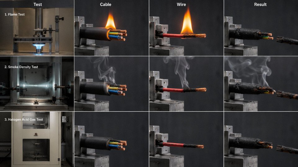
IEC 60332-1 tests a single cable in vertical flame propagation — minimum requirement for almost any installation. IEC 60332-3 tests a bunched cable installation (categories A, B, C, D by cable volume), which is what actually matters in cable trays, tunnels, and riser shafts. Specifying only 60332-1 compliance for a densely packed tray installation is a common spec error that can have serious fire consequences.
IEC 60754 measures acid gas and halogen content from combustion — relevant wherever fire fighter safety and equipment survival matter (data centers, rail, offshore). IEC 61034 measures smoke optical density, which governs evacuation visibility. LSZH cables must pass both; standard PVC cables typically fail both. Don’t accept a supplier’s claim of “low smoke” without an actual 61034 test report with optical density values.
Third-Party Certification Bodies
| Certification / Body | Primary Role | Typical Market Requirement |
|---|---|---|
| KEMA (now CESI/KEMA) | Independent type test witness and certification for MV/HV cables | Europe, Middle East project specs |
| DNV / Lloyd’s Register | Marine and offshore cable approval | Shipbuilding, offshore O&G |
| UL (Underwriters Laboratories) | North American market listing | USA, Canada, some Latin America |
| CCC (China Compulsory Certification) | Mandatory for cables sold in the Chinese domestic market | China domestic distribution |
| ISO 9001 | Quality management system audit — governs process, not product | Background requirement, most markets |
Jinda holds ISO 9001 certification covering its integrated R&D, production, and after-sales system, supporting full material traceability from incoming copper rod inspection through finished drum release.True
ISO 9001 certification requires documented incoming material inspection, in-process controls, and final release records, which directly support the traceability claim for a manufacturer of this scale and scope.
ISO 9001 in practice means documented incoming inspection for copper, aluminum, and compound batches — not just a supplier declaration. It means in-process checks at extrusion, stranding, and armoring, with records tied to drum serial numbers. It means final release can’t happen without all routine test results on file. In my experience, the fastest way to assess whether a supplier’s ISO 9001 is real or paper is to ask for a non-conformance report log from the last twelve months. A factory with zero NCRs is either not looking or not telling.
What Should Be Printed on the Cable and Drum
Per IEC and EN 50346 requirements, the cable print (the continuous print along the cable sheath) must include: voltage rating, applicable standard, conductor cross-section, manufacturer identity, and year of manufacture. Missing or incorrect print is a rejection ground — not a technicality. The drum label should add drum length, net weight, gross weight, drum number, and any project-specific reference.
If a drum arrives with an unreadable print or a label that doesn’t match the test report, stop. Matching drum numbers to test reports is the only way to confirm the cable you tested is the cable you installed.
Frequently Asked Questions About Wire vs Cable
Is all wire a cable?
No — and this trips up students and experienced buyers alike. Every cable contains conductors (wires), but a single unsheathed conductor is just a wire. What makes something a cable is the collective outer protective sheath enclosing the full assembly. Strip that sheath off a three-core NYY cable and you have three insulated wires, not a cable anymore. The sheath is doing real work: mechanical protection, moisture exclusion, UV resistance, and in many constructions, earthing continuity through the armor.
Can I use wire instead of cable outdoors or underground?
Flatly, no. A bare conductor or lightly insulated building wire — your standard H07V-U or THHN, for instance — carries no rating for direct burial, prolonged UV exposure, or soil moisture. Underground installations demand a proper cable construction: bedding over the cores, armor (typically steel wire armor or steel tape armor), and an outer sheath compound rated for soil contact and mechanical damage. The standard go-to types are NYY-J and N2XY per IEC 60502-1. N2XY uses XLPE insulation, which handles the thermal cycling better in circuits with variable load. Skipping the armor in a direct-burial trench and running insulated wire instead is the kind of decision that looks fine at commissioning and fails eighteen months later when a ground shift or rodent does what physics always intended.
What does the ‘mm²’ rating on a cable mean?
It refers to the nominal cross-sectional area of each conductor — not the overall cable diameter, not the insulation thickness, not anything you can measure on the outside. A 95 mm² conductor carries more current than a 50 mm², but the actual outside diameter of the finished cable depends on insulation grade, voltage class, armor type, and sheath thickness. Voltage drop calculations, ampacity tables, and fuse coordination all key off the conductor cross-section. The physical cable diameter matters for conduit fill and cable tray loading — those are separate calculations.
How do I know if a cable is genuine and not counterfeit?
Start with the print legend. Every meter of legitimate cable should carry continuous ink-printed text on the outer sheath showing voltage rating, standard reference (IEC 60502, BS 5467, or equivalent), conductor cross-section, number of cores, and manufacturer name. Missing fields or smudged, irregular printing are immediate red flags. Beyond that, request third-party type test certificates and cross-reference the certificate number directly with the issuing body’s online registry — KEMA, CESI, CPRI, and others all maintain searchable databases. A supplier who hesitates to provide traceable certificates is telling you something.
Jinda cables carry third-party type test certification traceable through issuing laboratory registriesTrue
Reputable manufacturers producing for export markets are required to obtain and maintain third-party type test certificates from accredited laboratories; these are verifiable through the issuing body's online registry as a standard industry practice.
What is the difference between a screened cable and an armored cable?
A screen — metallic foil, copper braid, or a combination — wraps the conductor assembly to block electromagnetic interference. It is an electrical function, not a mechanical one. Armoring, whether steel wire armor, steel tape armor, or aluminum wire armor, resists crush loads, tensile stress, and rodent attack. A cable can be both: many instrumentation cables in process plants are screened for signal integrity and armored for the physical environment. Specifying one when you need both is a common field mistake.
How long does a power cable last in service?
IEC 60216 thermal aging methodology and decades of field data point to a design life of roughly 30 to 40 years for well-installed XLPE power cables — assuming the installation was done correctly in the first place. That range narrows quickly with sustained overloading, repeated thermal cycling above rated temperature, or water treeing in wet environments where longitudinal water-blocking tape or compound wasn’t specified. Mechanical damage during pulling, particularly in conduit bends where the cable jacket gets abraded, starts a degradation clock that thermal ratings alone won’t predict.
What is the minimum order quantity when sourcing cable from a manufacturer like Jinda?
It depends heavily on cable type and conductor size. For standard low-voltage power cables — NYY, N2XY, armored multicore — practical production minimums typically run somewhere between 500 and 1,000 meters per size, give or take depending on conductor cross-section and core count. Larger conductor sizes or unusual constructions may require full drum quantities to justify the tooling setup. For medium-voltage or custom-construction cables, project-quantity ordering is the norm rather than the exception. Jinda handles both bulk supply contracts and project-specific procurement, supplying to customers across more than 50 countries — so whether the requirement is a single project cable schedule or an ongoing distribution agreement, the conversation is worth having early, before the procurement timeline gets compressed.
Partnering with Jinda Special Cable Group for International Cable Supply
If you’ve read this far, you already know that specifying the wrong product — confusing a single-conductor wire with a multi-core armored cable, or accepting a PVC-insulated substitute where XLPE was called for — creates real costs on-site. The next question is whether your supplier actually has the infrastructure to deliver what the specification demands, at volume, on schedule, with documentation that survives a third-party audit. That’s where manufacturing scale stops being a marketing bullet and starts being an operational reality.
Five Production Bases, One Quality System
Jinda operates five manufacturing sites across China, covering a combined 470,000 m² of production floor. That footprint matters in practice because it allows parallel production runs across different cable families. A large infrastructure project — say, a solar farm requiring both medium-voltage collection cables and DC string cables simultaneously — doesn’t have to wait for one line to finish before the other starts. Capacity conflicts that routinely delay single-factory suppliers are largely a scheduling problem here, not a capacity ceiling. All five bases operate under the same quality management framework, so a test report issued from one facility carries consistent meaning.
Product Range: IEC-Compliant Across the Spectrum
The catalogue covers low-voltage power cables to IEC 60502-1, medium-voltage cables to IEC 60502-2, control and instrumentation cables, mining cables rated for the mechanical and chemical abuse of underground environments, renewable energy cables (both solar DC and wind turbine variants), marine cables to IEC 60092, and fire-resistant plus LSZH types for transit, commercial buildings, and offshore platforms. Having all of these under one quality system is genuinely useful for EPC contractors who want to consolidate vendor lists and reduce the number of separate factory audits on a project.
In-House R&D and Type-Testing Capability
The on-site laboratory carries full IEC type-testing capability. For procurement managers, that means custom cable development — unusual conductor configurations, non-standard voltage classes, specific fire performance requirements — doesn’t get routed to a third-party design house with its own lead times and margins. In my experience, the projects that generate the most supplier friction are the ones with a slightly non-standard requirement: a 3.6/6 kV cable with a specific outer diameter constraint, or a trailing cable for a mobile machine that needs a flexibility class the standard catalogue doesn’t list. Having the engineering capability in-house compresses that development cycle considerably.
Jinda holds IEC type test certificates for its core cable product familiesTrue
IEC type testing is conducted by accredited third-party laboratories against published IEC standards; certificates are verifiable documents, not self-declarations, and Jinda makes these available to buyers during the qualification process.
How International Orders Actually Move
The typical supply process for an international project runs: technical consultation and specification review, sample submission and approval, type test report provision, production scheduling with agreed milestones, third-party inspection at the factory (SGS, Bureau Veritas, and similar are regularly accommodated), and container loading supervision with packing list and shipping documentation. Jinda currently serves active customers across Southeast Asia, the Middle East, Africa, Europe, and South America — roughly 50-plus countries. That’s not a claim about brand recognition; it’s a statement about logistics familiarity and export documentation experience, which matters when your project is in a country with specific import certification requirements.
Technical Support After the Sale
Commodity cable suppliers ship product and move on. Jinda maintains a dedicated engineering team available for cable selection guidance, installation advisory, and fault analysis. If a drum arrives on-site and something looks wrong — unusual jacket hardness, a diameter that doesn’t match the datasheet, a question about bend radius during cable pulling — there’s an actual engineer to contact, not a general sales inbox.
Submit Your Specification for Review
If you have a bill of materials, a project specification, or even an incomplete draft inquiry, the straightforward next step is to submit it for a technical review and competitive quotation. Typical response time for a detailed technical reply is 24–48 hours on business days. Reach out through the contact page with your cable type, voltage class, quantity, and delivery timeline — and if the spec has gaps, the engineering team will flag them before they become site problems.