Misidentified control wiring is one of those problems that looks minor until it isn’t. A technician grabs the wrong conductor size during a panel retrofit, the voltage drop across a 30-meter run pushes a PLC input below its threshold, and suddenly a conveyor line is faulting intermittently at shift change — the kind of fault that takes days to trace because nothing is obviously wrong. Scrap accumulates, maintenance burns overtime, and the root cause turns out to be a 1.0 mm² wire where a 2.5 mm² should have been. That gap between “close enough” and “correct” is exactly where control wiring failures live.
Control wiring refers to the conductors, cables, and associated insulation systems used to carry low-power signals, switching commands, and logic-level voltages between control devices — PLCs, relays, sensors, switches, and terminals. Conductor sizes typically run from 0.5 mm² up to 6 mm², with voltage ratings spanning 300/500 V to 600/1000 V, depending on circuit type and installation environment. Governing standards include IEC 60227, IEC 60502, UL 508, and NFPA 79.
What makes control wiring genuinely interesting — and genuinely consequential — is that the same 24 VDC circuit behaves very differently depending on conductor material, insulation chemistry, conduit fill, and ambient temperature. The wire that works fine in a climate-controlled panel room can fail within a season inside a steel mill switchgear cabinet running at 60 °C. Understanding the common types, what differentiates them, and where the selection decisions actually matter is what separates a reliable installation from one that generates service calls.
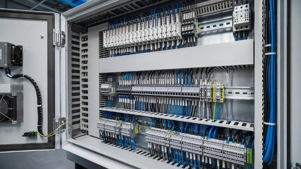
Core Components That Make Up a Complete Control Wiring System
A control wiring installation is not just cable. It’s an assembly of interdependent physical elements — and specifying one without understanding the others is how panels end up rewired six months after commissioning.
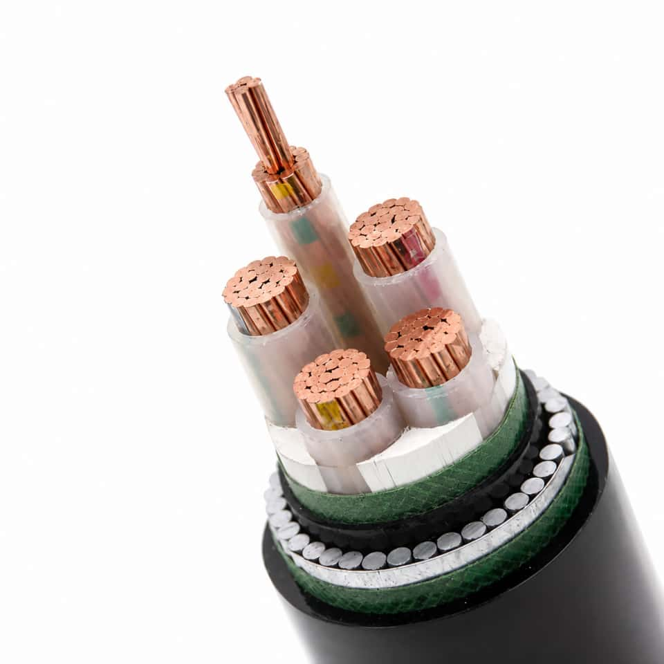
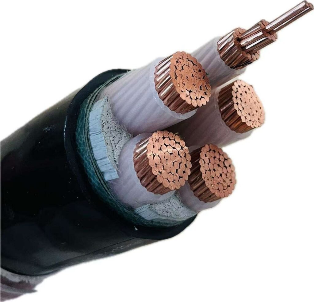
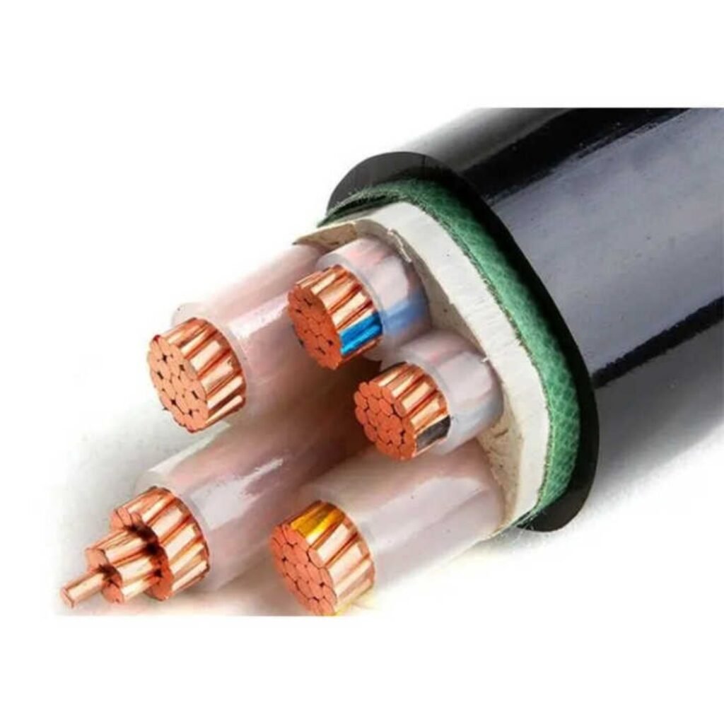
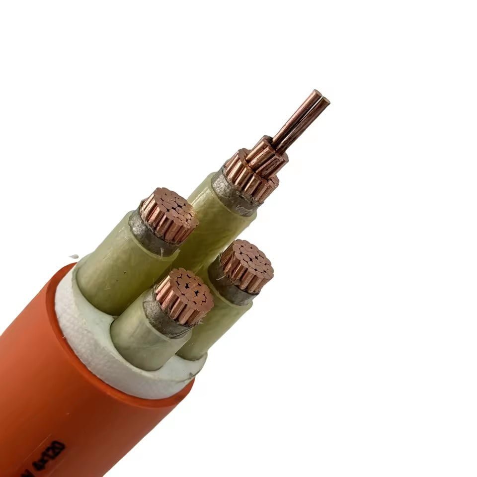
Control Cable
The backbone of any control circuit. Multi-core control cables typically run from 0.5 mm² up to 4 mm² per conductor for signal and command duties, though you’ll occasionally see 6 mm² cores used where a control circuit carries a meaningful current load or where the run exceeds 50–80 meters and voltage drop becomes a real factor. Screened cables (overall braid or foil with drain wire) are not optional in environments with variable-speed drives, welding equipment, or any significant switching noise — unscreened cable in those conditions causes spurious relay trips and sensor dropouts that are genuinely difficult to trace.
Jacket material matters more than people give it credit for. PVC is still the workhorse: cheap, flexible, widely available, serviceable from roughly -15°C to +70°C. LSZH (Low Smoke Zero Halogen) is the right call for confined spaces, tunnels, or any installation where personnel can’t evacuate quickly — the difference in smoke toxicity during a cable fire is not subtle. XLPE-insulated control cable handles higher sustained temperatures (up to around 90°C) and resists chemical exposure better, which matters in food processing, chemical plant, or outdoor-routed installations where UV degradation or intermittent fluid contact is realistic.
Terminal Blocks and DIN-Rail Systems
Every field wire eventually lands on a terminal block. The choice between screw-clamp, spring-cage, and push-in types is partly preference and partly environment. Spring-cage terminals (Phoenix Contact PT series, Weidmüller Klippon, and equivalents) hold up better under vibration — a screw terminal in a compressor skid panel will back off over time if nobody re-torques it during annual maintenance, and most sites don’t. Push-in terminals are fast for high-density wiring, though they need properly ferruled conductors to work reliably.
Color-coding is not decorative. Blue for neutral or DC negative, yellow-green exclusively for protective earth — these are IEC conventions that maintenance electricians depend on, especially when they’re fault-finding under pressure. Mixing them to use up spare stock is a decision that costs somebody hours of troubleshooting later.
Pilot Devices
Pushbuttons, selector switches, emergency-stop buttons, proximity sensors, thermostats, pressure switches, float switches — these generate the input signal that everything else responds to. Emergency-stop devices must comply with IEC 60947-5-5 and be rated for the required stop category; a standard momentary pushbutton substituted for an e-stop is a safety incident waiting to happen. Proximity sensors introduce a wiring subtlety: NPN vs. PNP output determines how the device sinks or sources current to the PLC input card, and getting that wrong means the input never activates even though the sensor is functioning perfectly.
Control Relays and Contactors
Relays serve as the amplification layer — a 24 VDC signal from a PLC output module can’t directly switch a 230 VAC coil contactor in most designs. Intermediate relays bridge that gap, with coil voltages matched to the control circuit (24 VDC, 120 VAC, 240 VAC being the common options) and contact ratings typically in the 6–16 A range for relay outputs. Auxiliary contact blocks on contactors extend functionality without adding hardware; a normally-closed auxiliary wired as a seal-in or interlock is basic ladder logic, but specifying the contactor without confirming available auxiliary pole count is a common panel-design oversight.
Protective Devices for Control Circuits
Control fuses — fast-blow, typically 0.5 A to 10 A depending on the circuit — protect transformer secondaries and individual device branches. MCBs rated for control circuit duty (Curve B or C, 1–6 A range) offer resettability where nuisance fuse replacement would slow operations. Long cable runs to remote I/O or field instruments benefit from surge protection devices at both ends; a 200-meter run to an outdoor sensor is an effective antenna during a thunderstorm.
Surge protection devices on long control cable runs to outdoor devices can prevent PLC input card damage during electrical stormsTrue
Long unshielded or partially shielded cable runs act as antennas, coupling transient voltages from lightning or switching events into sensitive PLC input circuits. SPDs rated to IEC 61643-21 clamp these transients before they reach the card.
Wiring Accessories
Ferrules (end sleeves) are non-negotiable for stranded conductors entering screw terminals — bare stranded wire fans under clamp pressure and creates a high-resistance joint that heats up. Color-coded ferrules by cross-section (red for 1 mm², black for 1.5 mm², blue for 2.5 mm² per common European convention) speed up assembly and inspection. Cable duct, conduit, and tie systems keep the installation maintainable; a panel wired without duct may look clean on day one, but pulling a single wire replacement after years of bundled routing is a significant job.
Identification Materials
IEC 60204-1 clause 13 is explicit: every conductor needs to be identifiable at each end. Heat-shrink markers, clip-on ferrule legends, and printed wire number tags all satisfy this, but they only work if someone maintains the as-built documentation when changes are made. In practice, panels accumulate undocumented modifications over years of service, and a site with disciplined wire-tagging habits is noticeably faster to fault-find than one without. That’s not a soft benefit — it translates directly to mean time to repair.
Seven Most Common Control Wiring Configurations Used in Industry
Control circuits are not monolithic. Walk through enough panel shops and you start recognizing the same handful of topologies repeated across industries, adapted slightly for local codes or equipment quirks but fundamentally unchanged for decades. Here are the seven you will encounter most often, with enough operational detail to make real design decisions.
Two-Wire Control Circuit
The simplest form: a single pilot device — thermostat, pressure switch, float switch — wired in series with the load coil. When the device closes, the coil energizes. When it opens, the coil drops out. No latching, no memory.
The hazard is automatic restart. If power is lost and restored while the pilot device remains closed, the load re-energizes without operator action. For an HVAC fan or a sump pump, that is usually acceptable. For a conveyor carrying personnel, it is a serious safety violation. NFPA 79 and most machine safety standards explicitly require engineered justification before accepting two-wire control on machinery. Mark the drawing. Flag it at FAT.
Three-Wire Control Circuit with Seal-In (Memory)
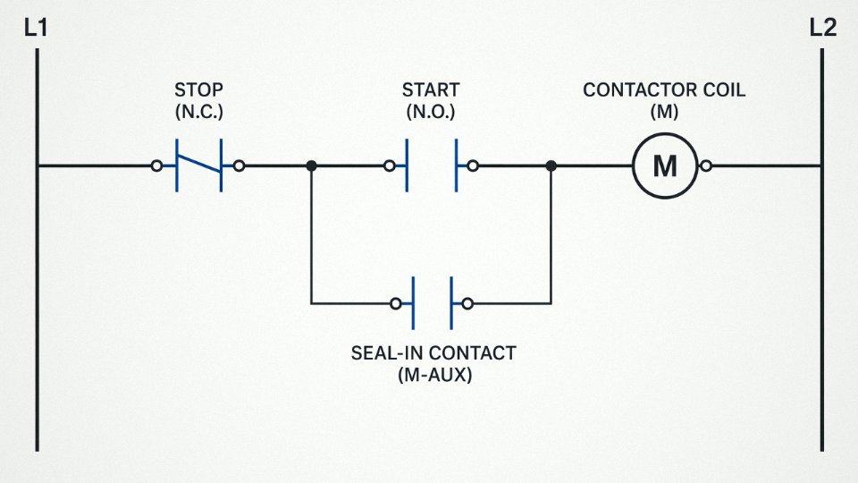
This is the workhorse of motor control. A momentary Start pushbutton, a momentary Stop pushbutton, and an auxiliary contact on the contactor wired in parallel with the Start button. Press Start, current flows through the auxiliary contact path, contactor seals in and holds itself energized. Press Stop, the series Stop contact opens, coil drops, auxiliary contact opens, and the circuit cannot re-latch until Start is pressed again.
Power interruption resets the latch. That is the design intent — it is what makes this circuit compliant with automatic restart requirements. The seal-in contact is normally rated for the control circuit voltage (typically 120 VAC or 24 VDC), not the motor power, so wiring gauge through that loop is usually 0.75 mm² to 1.5 mm², depending on circuit length and voltage drop budget.
Forward-Reverse Motor Control
Two contactors, mechanically interlocked via a bar that prevents both from closing simultaneously, and electrically interlocked by wiring a normally-closed auxiliary contact from each contactor in series with the opposite coil. If the Forward contactor is energized, its NC contact opens and physically breaks the path to the Reverse coil — even if someone manages to press both buttons at once. The mechanical interlock is the backup; the electrical cross-interlock is the primary. Never rely on only one of them. Phase reversal faults and burned contactor tips are the consequence of skipping the cross-wiring.
Multiple-Location (Multi-Pushbutton) Control
Start buttons from different stations wire in parallel; Stop buttons wire in series. Any Start can initiate, any Stop can halt. Typical on long conveyor lines — 50 m to 150 m or more — and bridge cranes where the operator position changes. Voltage drop across long runs can cause nuisance no-starts if undersized; check the coil’s minimum pickup voltage against your calculated drop at full run length.
Control Circuit with Pilot Lights and Fault Indication
Auxiliary contacts drive indicator lamps. A normally-open auxiliary on the run contactor powers the green “Run” lamp. A normally-closed auxiliary powers the red “Stop” lamp — it goes out when the motor runs. Fault indication typically uses a normally-open contact on an overload relay to energize an amber or red fault lamp and, in more complete panels, a buzzer circuit through a normally-closed silence pushbutton.
Keep pilot circuits isolated — either a dedicated control transformer (typically 120 VAC secondary, 50 VA to 150 VA depending on lamp and relay load) or a regulated 24 VDC supply. Mixing pilot circuits into an unprotected leg of 480 VAC or 600 VAC power invites transient damage and nuisance trips.
Reduced-Voltage and Soft-Start Control Wiring: Star-Delta Transition
Three contactors — Main, Star, Delta — sequenced by a timer relay. On Start, Main and Star energize simultaneously, connecting the motor windings in wye (Y) for reduced-voltage starting at roughly 58% of line voltage per phase. After a preset interval (commonly 5 s to 15 s, depending on load inertia), the timer opens the Star contactor, inserts a brief dead-band of around 50 ms to 100 ms to allow flux collapse, then closes the Delta contactor for full-voltage operation.
Skipping the dead-band in star-delta transition wiring causes a current transient that can exceed direct-on-line starting current.True
Without a brief open-circuit interval between star dropout and delta closure, the motor's residual magnetic flux can be out of phase with the incoming line voltage, producing a transient that often exceeds DOL inrush and defeats the purpose of reduced-voltage starting entirely.
The auxiliary contact wiring here is non-trivial. A normally-closed auxiliary on the Delta contactor must sit in series with the Star coil circuit, and vice versa, to enforce mutual exclusion. Miss that interlock and you will eventually see simultaneous Star-Delta energization — which is a phase-to-phase short through the contactor power poles.
Safety Relay and Emergency-Stop Loop Wiring
Dual-channel E-stop wiring runs both channels from the E-stop button through the safety relay module to ground, with the relay monitoring for channel symmetry, cross-faults, and welded contacts using forced-guided (positive-guided) relay technology. If one channel fails open while the other remains closed, the safety relay detects the asymmetry and either inhibits reset or drives outputs to safe state.
Per IEC 62061 and ISO 13849, achieving PLd or PLe typically requires two independent signal paths, cross-fault detection, and a monitored manual reset — meaning the reset button must be released and re-pressed after every E-stop event; automatic reset is not acceptable at these performance levels. Output contacts from the safety relay feed directly into the coil circuits of the motor contactors, not through an intermediate general-purpose relay that could mask a fault.
A common wiring mistake is using standard auxiliary contacts instead of forced-guided contacts in the feedback monitoring loop. Standard contacts can weld closed under fault conditions without the safety relay detecting the failure, leaving the machine in an apparently safe but actually unmonitored state.
Selecting the Right Control Cable: Conductor, Insulation, and Shielding Criteria
Getting cable selection wrong is one of the quieter ways a project bleeds money. The damage rarely shows up on day one — it shows up eighteen months later as nuisance trips on a 4–20 mA loop, premature jacket cracking near a compressor, or a ground fault that takes a shift to trace because nobody shielded the VFD signal cables properly.
Conductor Sizing by What the Circuit Actually Carries
For instrument and sensor loops — thermocouples, pressure transmitters, proximity switches — 0.5 mm² to 0.75 mm² is standard. Current draw is negligible; the sizing decision is almost entirely about mechanical robustness and loop resistance over long runs. Once you push a sensor loop past roughly 200 m, check the voltage drop calculation even at those small currents, because a 24 VDC PLC input has less tolerance than people assume.
Relay and contactor coil wiring typically lands at 1.0 mm² to 1.5 mm², which is comfortable for coil inrush on a 120 VAC contactor. Don’t obsess over upsizing here — 1.5 mm² is almost always the ceiling unless you have an unusually long panel-to-field run combined with significant coil current.
Where control wiring carries real load — motor brake coils, solenoid valve actuators drawing 2–5 A continuously, motorized damper actuators — you’re looking at 2.5 mm² to 4 mm² depending on run length and ambient temperature. This gets missed during panel design more often than it should. A brake coil running at slightly elevated temperature on undersized wire will eventually fail the insulation, and the failure mode looks like a random brake fault rather than a wiring problem.
Conductor Material: Copper Grade and Stranding Class
Plain annealed copper is fine for most indoor industrial environments. Humid enclosures, coastal plants, or anything that qualifies as a marine environment deserves tinned copper — oxidation on an untinned termination inside a screw terminal is a slow, intermittent resistance fault that is genuinely annoying to diagnose.
Stranding matters operationally. Class 5 or Class 6 flexible stranding belongs in panel wiring that gets flexed during installation or door swing; Class 2 compressed stranding is the standard choice for fixed conduit runs where you want good termination grip without wire fraying. Using Class 2 in a drag chain is a straightforward recipe for fatigue fractures within a year.
Insulation and Jacket Selection
PVC to IEC 60227 is the workhorse — economical, rated to 70 °C, perfectly adequate for a standard indoor MCC room or control panel. The moment you’re routing through a tunnel, a passenger rail application, or any enclosed public space, LSZH (low smoke zero halogen, IEC 60332-3) is not optional regardless of cost delta. Smoke toxicity in confined spaces is a life-safety issue, not a specification checkbox.
Near heat sources — compressor skids, furnace hoods, areas where ambient regularly sits above 50–55 °C — XLPE insulation rated to 90 °C under IEC 60502 is the appropriate choice. PVC gets soft and sticky in sustained heat. It won’t fail immediately, but the jacket will deform against conduit edges and the insulation resistance will drop over time.
Shielding Decisions
Unshielded multicore cable in metallic conduit is fine for hardwired relay logic — the conduit itself provides adequate screening for 24 VDC or 120 VAC digital signals. Spending money on screened cable for dry contact I/O in steel conduit is over-specification.
Analog 4–20 mA loops need individually screened pairs (IS) with the shield grounded at one end only. This is non-negotiable on any run that passes near motor cables or bus ducts. An overall braid alone won’t protect individual pairs from crosstalk inside the cable.
VFD environments are the hard case. High-frequency switching noise from variable frequency drives couples aggressively into nearby signal cables. Specify overall foil-plus-braid with a drain wire, aim for shield coverage above 85%, and route signal cables at least 300 mm away from VFD output cables where physically possible. Transfer impedance below roughly 50–100 mΩ/m at the relevant frequency range is the benchmark worth asking your supplier to confirm in writing.
Individually screened pairs provide better noise rejection for analog signals than an overall braid shield alone in multicore control cables.True
An overall braid shields the cable bundle from external interference but does not prevent crosstalk between individual pairs inside the cable. Individually screened pairs interrupt the capacitive and inductive coupling paths between cores, which is why IS construction is specified for analog instrumentation loops in industrial environments.
Voltage Ratings and Flame Retardancy
Intra-panel wiring between terminals in the same enclosure: 300/500 V rating is sufficient and standard. Cable that exits a cabinet and runs in a tray or conduit alongside 400 V power cables should be rated 600/1000 V — the issue isn’t the control circuit voltage, it’s fault voltage exposure from adjacent power conductors.
Flame retardancy grade selection follows installation type. IEC 60332-1 (single-cable flame test) covers most standard fixed installations. IEC 60332-3-24 (bundled cable flame test, Category C) is required where cables are installed in groups on trays — which is most real plants. Ordering single-core-tested cable and then running it in a 200 mm wide tray bundle is a compliance gap that occasionally surfaces during insurance audits.
Color Coding by Destination Market
This is a procurement detail that bites projects when cable arrives on-site and doesn’t match local practice. IEC and European installations use black cores numbered sequentially, or brown/black/grey active conductors with blue neutral and green-yellow earth. North American NEC practice uses black, red, and blue for phase conductors, white for neutral, and green for equipment ground. Order cable that matches the destination standard — rewiring a panel because the color coding triggered a local inspection rejection is an avoidable cost.
Jinda’s control cable range covers screened and unscreened multicore constructions across PVC, LSZH, and XLPE insulation systems, produced across five manufacturing bases in China with custom core counts and cut lengths available for bulk project supply. For projects specifying both IEC and NEC color conventions in the same facility — which happens more often than you’d expect on multinational capital projects — it’s worth confirming color coding options at the RFQ stage rather than during manufacturing.
Step-by-Step Control Wiring Installation Best Practices for Panel Builders
Good wiring practice starts before a single wire gets cut. Pull the approved wiring diagram and terminal schedule, lay them side by side with the bill of materials, and reconcile every line item. Discrepancies between the BOM and the schematic — a wrong ferrule size, a missing shield drain wire, a terminal block rated for 6 mm² where the drawing calls for 10 mm² — are always cheaper to fix on paper than on the panel floor. Verify cable drum or coil lengths against your cut list before anything goes on the bench. A mid-run joint in a control circuit is not a code violation in every jurisdiction, but it is a maintenance headache and a latent fault point. Avoid it.
Segregation: The Rule Most Shops Get Wrong
Route control wiring in dedicated cable ducts or conduit, physically separated from power cables carrying more than 50 V. IEC 60204-1 clause 14.1 calls for at least 200 mm of separation, or a metallic divider where that spacing is not achievable. In practice, many panel builders underestimate how quickly induced noise from a 480 V motor feeder running parallel to a 24 VDC signal cable can corrupt encoder feedback or cause spurious PLC inputs — especially on long runs or in panels with VFDs. A grounded steel separator costs almost nothing; a noise-related field callback costs a lot more.
Termination Sequence and Ferrule Practice
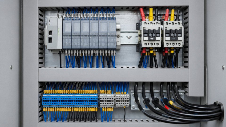
Strip insulation to the depth marked on the terminal manufacturer’s gauge, not by eye. For stranded conductors — which covers most flexible control cable from 0.5 mm² up through 4 mm² — crimp an appropriately sized end sleeve (ferrule) before inserting into a screw or spring-cage terminal. Skipping ferrules on stranded wire is one of the most common causes of intermittent faults after vibration or thermal cycling. Torque screw terminals to the manufacturer’s specification; for 1.5 mm² terminals this typically lands somewhere between 0.5 N·m and 1.2 N·m depending on the terminal design. Use a calibrated torque screwdriver — a “feel check” is not repeatable across a crew of four wiremen working a tight deadline.
Inserting un-ferrulled stranded conductors into screw terminals significantly increases the risk of loose-wire faults over timeTrue
Without a ferrule, individual strands can splay or break under screw clamping force, reducing effective contact area and creating resistance that increases with vibration and thermal cycling — a well-documented failure mode referenced in IEC 60999-1 termination standards.
Wire Numbering and Labeling
Apply heat-shrink markers or clip-on wire numbers at both ends of every conductor before it gets dressed into the duct. IEC 60204-1 requires each wire to be identifiable at every termination point — not just at the source end. This matters enormously during troubleshooting at 2 a.m. with someone who did not build the panel.
Pre-Energization Testing
Before applying any power, perform a point-to-point continuity check with a calibrated digital multimeter. Then do an insulation resistance test at 500 VDC between control conductors and earth. New installations should read well above 100 MΩ; anything below 1 MΩ warrants investigation before you proceed.
Commissioning Sequence
Energize the control transformer first and confirm secondary voltage is within tolerance. Then manually operate each pilot device — pushbuttons, selector switches, proximity sensors — one at a time, verifying the correct output response at the controller. Test interlocks by deliberately commanding conflicting states; the control logic should prevent both outputs from energizing simultaneously. Run the E-stop loop last: verify the safety relay reaches safe state within the required response time under the plant’s actual supply conditions, not just on the bench.
Documentation and Handover
Update as-built schematics to capture every deviation from the issued-for-construction drawing — even minor ones like a wire rerouted around an obstruction or a terminal number reassigned. Record continuity test results, insulation resistance readings, and torque check confirmations in the commissioning dossier. Attaching a QR code or asset tag to the panel face that links directly to the digital schematic file costs almost nothing and saves the next engineer a genuine amount of time. Panels that ship with clean, current documentation get recommissioned faster after moves, retrofits, and fault repairs.
International Standards and Compliance Requirements for Control Wiring
Getting the cable specification right means nothing if the installation fails a third-party inspection or, worse, a CE audit six weeks before shipment. Standards compliance isn’t a paperwork exercise — it directly determines which cable constructions you can use, how circuits must be protected, and whether your machine gets export clearance.
IEC 60204-1: The Global Baseline for Machine Control Wiring
Most industrial machinery projects worldwide start here. IEC 60204-1 (Safety of Machinery — Electrical Equipment of Machines) covers conductor sizing, color-coding requirements, earthing arrangements, terminal identification, and control circuit protection methods in a single document. For control wiring specifically, it prescribes minimum cross-sections based on current load — typically 0.5 mm² to 1.5 mm² for low-current signaling circuits, larger where relay coil or solenoid loads demand it — and it mandates that control circuit conductors be protected against overcurrent independently from power circuits. Color codes matter here too: blue for neutral conductors, yellow-green strictly for protective earth, and no mixing those functions under any circumstance. Plants that ignore the color rules usually discover the problem during a machinery safety audit, at which point someone is re-wiring a panel that’s already been installed.
NFPA 79: North American Machinery Wiring
NFPA 79 is the North American equivalent and tracks closely with IEC 60204-1 in structure, but it has specific mandates that catch importers off guard. Control circuits must operate at 120 VAC or 24 VDC — 240 VAC control circuits are not permitted in new machinery destined for the US market. Wire colors follow NEC conventions: white or gray for neutral, green or bare for equipment grounding. Critically, NFPA 79 requires UL-listed components throughout the panel, which means a cable certified only to IEC standards may not satisfy a UL 508A panel shop without additional documentation or recertification. If you’re building machines for both North American and European customers on the same line, the cable specification needs to be resolved early — not during final inspection.
IEC 60364 Series: When Control Cables Leave the Machine
Once control cables exit the machine enclosure and run through a building — through conduit, cable tray, or buried duct — IEC 60364 takes over from IEC 60204-1. This series governs wiring methods, cable installation practices, protective device coordination, and verification testing for low-voltage electrical installations. The installation method (bunched in tray, clipped direct, in conduit) directly affects allowable current-carrying capacity and, by extension, whether you need to upsize conductors to stay within temperature limits. Overlooking this boundary between machine and building wiring is a common source of failed inspections on large capital projects.
Cable Product Standards: IEC 60502-1 and IEC 60227
These are the manufacturing-level standards — they define what the cable itself must be, not how you install it. IEC 60502-1 covers extruded solid dielectric cables up to 30 kV, while IEC 60227 applies specifically to PVC-insulated cables at 300/500 V and 450/750 V ratings, which covers the majority of control cable applications. Test voltages, minimum insulation thickness, conductor DC resistance per unit length, and flame-retardant performance are all specified here. When you’re evaluating a cable supplier’s test reports, these are the standards you verify against.
Jinda control cables are manufactured and tested to IEC 60502-1 and IEC 60227 requirements, with third-party test certificates available for project documentation.True
Jinda operates five production bases in China with integrated R&D and quality systems; third-party certification is standard practice for export cable suppliers serving 50-plus countries.
Functional Safety Standards: IEC 62061 and ISO 13849
These standards apply the moment your control wiring is part of a safety function — E-stop loops, light curtain interfaces, gate interlocks, or two-hand control circuits. ISO 13849-1 defines Performance Levels (PLa through PLe); IEC 62061 uses Safety Integrity Levels (SIL 1 through 3). Both require that the wiring architecture itself — not just the devices — support the target safety level. A PLd E-stop circuit wired as a single-channel loop using unshielded cable routed alongside high-noise power conductors will likely fail a functional safety validation, regardless of how good the safety relay is. Channel separation, cable routing, and connection integrity all feed into the calculation.
Regional Approvals: Matching the Destination Market
Beyond the IEC/NFPA framework, market access depends on regional certifications that procurement teams need to track explicitly.
| Market | Required Approval | Key Cable Implication |
|---|---|---|
| North America | UL 508A panel listing; UL-rated cable | IEC-only cables need additional evaluation |
| European Union | CE marking (LVD 2014/35/EU + Machinery Directive 2006/42/EC) | IEC-certified cable generally accepted |
| China | CCC (China Compulsory Certification) | Domestic installations require CCC-marked cable |
| Russia / EEU | EAC certification | Separate testing; plan 3–6 months lead time |
The practical consequence: a machine built in Europe for export to Russia needs EAC documentation for the complete assembly, and the cables specified need to either carry EAC marks or be accepted under the EAC machinery declaration. Sorting this out after manufacturing is painful and expensive.
Jinda’s technical and export teams have worked through these certification routes across 50-plus countries, and dual IEC/UL certification is available on applicable cable types. For projects with specific regional approval requirements, requesting the full certificate package at the quotation stage — not the shipping stage — is the straightforward way to avoid delays.
Troubleshooting the Five Most Frequent Control Wiring Failures
Control circuits are unforgiving in one specific way: a single broken link anywhere in the series chain and the whole loop goes dead. Most unplanned downtime on the plant floor traces back to a handful of repeatable failure modes — and experienced maintenance technicians learn to attack them in a fixed sequence rather than chasing symptoms.
Open Circuit — No Control Voltage at the Load
Start at the supply rail, not the load. With the circuit live and a voltmeter in voltage-measurement mode, probe downstream through each series element in turn: supply fuse, stop button NC contact, overload relay NC contact, then across the coil terminals. The point where voltage disappears is where the break lives. Simple in theory; the practical complication is that a loose terminal may read near-correct voltage under the light load of the voltmeter probe but drop to near-zero the moment the coil pulls in. So apply load — energize the coil — and re-check. Corroded terminals on 24 VDC circuits are particularly deceptive because the low driving voltage has almost no ability to push through even a thin oxide layer. A terminal that looks fine visually can add 8–15 Ω of resistance, which is invisible on 480 VAC but fatal on a 24 V circuit.
Spurious Tripping or Unwanted De-Energization
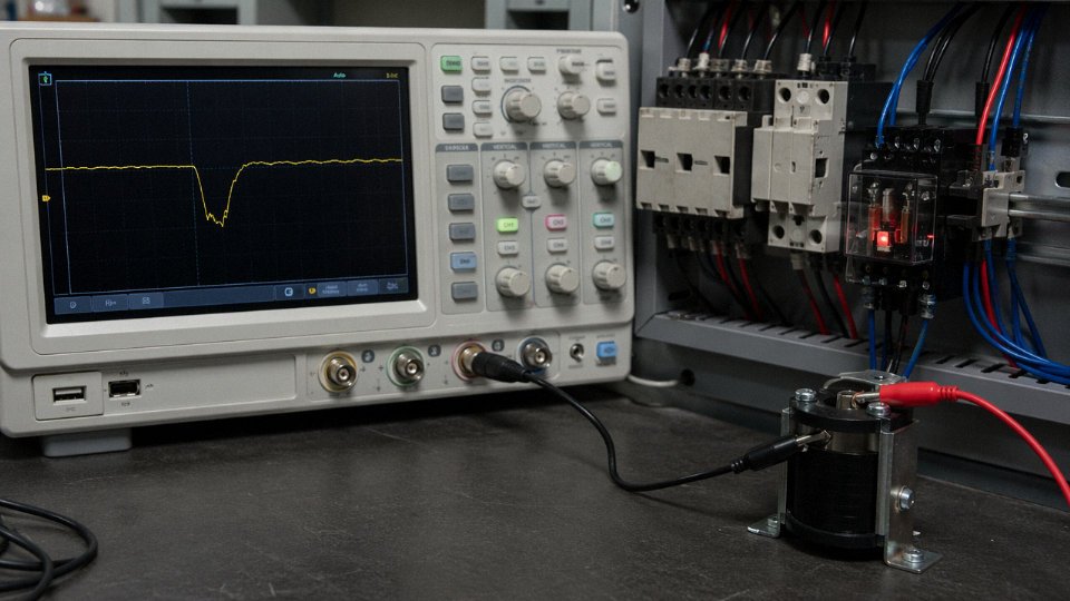
Intermittent faults are genuinely maddening and often get misdiagnosed as PLC software issues. The real culprits are usually a marginal NC contact with insufficient gap after years of wear, a ring terminal that has micro-fractured internally from vibration, or EMI coupling from an unshielded cable run routed alongside a VFD output. A standard voltmeter will miss all three. Use a data-logging multimeter or — if you have one available — a storage oscilloscope across the coil supply. Look for voltage dips below the coil’s hold-in threshold, which is typically 75–85% of rated voltage for AC contactors. One transient captured at 18 ms duration explains the random dropout nobody could reproduce.
Control Fuse Repeatedly Blowing
Don’t just upsize the fuse. That is the single most dangerous maintenance shortcut in a control panel. Three distinct root causes produce this symptom: a true overload on a small control transformer (check VA loading against transformer nameplate), a partial short in wiring or coil insulation (measure insulation resistance between conductors and ground — less than 1 MΩ on a 500 VDC Megger reading is suspect), and an undersized fuse installed by someone who grabbed the nearest one from the drawer. Measure coil inrush current with a clamp meter capable of capturing peak values, then verify the fuse I²t rating is appropriate for that inrush duration. Many standard glass fuses have I²t ratings far too low for contactor coil inrush; time-delay fuses or type-T fuses are almost always the right specification here.
Upsizing a control fuse without identifying the root cause of repeated blowing creates a fire and equipment damage risk.True
A control fuse is the last protection against a wiring short or coil insulation failure. Replacing it with a larger rating eliminates that protection and allows fault current to persist long enough to damage wiring insulation, initiate carbonized tracking paths, or cause a fire inside the enclosure.
Relay or Contactor Coil Premature Failure
Nine times out of ten the cause is thermal, electrical, or both. Measure coil voltage with the contactor fully energized — not just at the supply rail, but directly across the coil terminals. Consistently 10–15% above nameplate rated voltage accelerates insulation degradation significantly; the relationship is roughly exponential with temperature. Check whether the control transformer tap is correctly set for your supply voltage. Enclosure ambient temperatures above 40–45°C compound the problem fast, especially in summer months when panel cooling fans have accumulated a season of dust on their filters.
Incorrect Operation After Rewiring
Before energizing after any panel modification, perform a logic trace against the actual wiring diagram — not the “as-found” sketch someone drew at midnight. Verify that every NC interlock contact is physically wired normally-closed, not inadvertently left open or wired in parallel with another contact. Confirm every wire number matches the terminal schedule. A photographic record of the before state takes two minutes and has saved countless re-troubleshooting sessions.
Shield and Grounding Problems on Instrumentation Cables
The standard rule — ground the shield at one end only for low-frequency or DC signal circuits, both ends for high-frequency — is correct in principle but requires knowing what is actually coupling into the cable. For most PLC analog I/O runs, single-point grounding at the panel end is the starting point. Ground loops show up as a DC offset or 50/60 Hz ripple on the signal. Physical separation from VFD output cables is the cheapest first fix, often before any regrounding work. A 300 mm separation from VFD cables eliminates a surprising proportion of noise complaints without any wiring changes at all.
Preventive Maintenance Checklist
Annual torque re-checks on all control terminal screws — using the torque value on the terminal block datasheet, not guesswork — catch roughly half of potential open-circuit faults before they happen. Trend insulation resistance readings over multiple years rather than judging pass/fail on a single measurement; a value dropping from 500 MΩ to 50 MΩ over three years is more actionable than a single 50 MΩ reading in isolation. Measure contact resistance on pilot devices annually with a low-resistance ohmmeter; anything above 0.5–1 Ω on a control-voltage circuit deserves attention. And photograph every termination point showing discoloration, corrosion, or arcing evidence — that photographic record is what makes the maintenance argument to management when capital repair budget is tight.
Frequently Asked Questions About Control Wiring
What is the difference between a control wire and a power wire?
The short answer: one gives orders, the other does the work. Control wires carry low-energy command signals — typically well under 10 A — to relay coils, PLC input cards, sensor loops, and pilot devices. Power wires carry full load current to motors, heaters, drives, and any other consuming device. In practice, the distinction shows up in three places: cross-section (control wires are almost always smaller), routing (they run separately, for reasons covered below), and color coding (which varies by regional standard but is never arbitrary). A control wire feeding a 24 VDC relay coil might carry 80 mA. The power wire feeding the motor that relay switches might carry 80 A. Mixing them up — even briefly — is how panels get damaged during commissioning.
What size wire is used for control wiring?
For the vast majority of relay coil, pilot light, and PLC discrete I/O circuits, 0.75 mm² or 1.5 mm² copper conductors cover the requirement. Most plants standardize on 1.5 mm² because the marginal cost over 0.75 mm² is small and it survives terminal overtorquing better in rough maintenance environments. Step up to 2.5 mm² when actuator solenoids, motor brakes, or other inductive loads push circuit current past roughly 6 A — check the device datasheet, not just the coil voltage.
Voltage drop matters more than many panel designers admit. On a large site where the pushbutton station is 150–200 meters from the MCC, a 24 VDC circuit on 1.5 mm² copper can lose 0.6–1 V round-trip depending on exact cable temperature and termination resistance. Most 24 VDC relay coils operate down to about 18–19 V, so there’s some margin, but not infinite. Either upsize the conductor or switch to a 120 VAC control circuit where lower current makes the same run less vulnerable to drop.
Can control wiring and power wiring share the same conduit?
Generally no, and both IEC 60204-1 and NFPA 79 are explicit about it. The concern is twofold: electromagnetic interference from high-current switching transients coupling into sensitive signal circuits, and fault containment — a ground fault on a power conductor in a shared conduit can impose damaging voltage on control wiring rated for a lower level. The narrow exception both standards permit is when every conductor in the conduit is rated for the highest voltage present. In practice, that means upsizing all your control cable insulation to match your power cable rating, which usually costs more than just running a second conduit.
What does a three-wire control circuit mean?
It’s the classic Start-Stop-Seal-In motor control arrangement: three conductors run between the pushbutton station and the motor starter. One carries the stop signal, one carries the start signal, and the third carries the seal-in path through the auxiliary contact. That auxiliary contact is the key — it latches the starter energized after you release the start button, and it drops out on any interruption, whether intentional or a power fault. The motor does not restart automatically when power returns. That’s not a quirk; it’s a safety feature required by most machinery standards, and it’s why two-wire (maintained-contact) control is restricted to specific applications where automatic restart is explicitly acceptable and documented.
What color is control wiring?
It depends entirely on which standard governs the installation, and getting it wrong creates real problems during maintenance at 2 a.m.
Under IEC/European practice (IEC 60204-1), control phase conductors are typically black or grey with numeric ferrule identification doing the heavy lifting. In North American installations under NEC and NFPA 79, ungrounded 120 VAC control conductors are black or red; the grounded neutral is white or grey. For 24 VDC, positive is usually red or brown and negative blue — broadly following IEC 60446 color conventions even in mixed-standard plants. Some facilities run their own internal color standard for 24 VDC versus 48 VDC versus 120 VAC circuits, which is fine as long as it’s documented consistently and doesn’t contradict any applicable code requirement.
IEC 60204-1 requires control circuit conductors to be identified by color or marking at every termination point.True
IEC 60204-1 clause 13.2 requires conductor identification either by color coding or by alphanumeric marking, consistently applied throughout the installation. Color alone may be insufficient where multiple voltage levels share similar colors, which is why ferrule numbering is standard practice in industrial panels.
How is control wiring tested after installation?
Minimum acceptable testing has two phases. First, point-to-point continuity on every conductor to confirm correct termination and catch wiring errors before power-up. Second, insulation resistance testing at 500 VDC, with a pass threshold of at least 1 MΩ between conductors and between conductors and earth — lower readings suggest damaged insulation, trapped moisture, or a pinched conductor somewhere in the conduit run. After those checks pass, functional testing covers every pilot device, interlock, and safety circuit under controlled conditions, with results recorded in a commissioning test record as required by IEC 60204-1. Skipping the documentation step creates liability exposure and makes future troubleshooting significantly harder.
What is the maximum cable run length before voltage drop causes problems?
There’s no single number — it depends on conductor cross-section, ambient temperature, load current, and the operating voltage range of your devices. As a working example: a 24 VDC relay coil drawing 50 mA, wired with 1.5 mm² copper at 20 °C over a 200-meter round trip, produces roughly 0.7 V drop. Most coils tolerate that. Push the run to 400 meters on the same wire and the same coil, and you’re at 1.4 V drop — still likely acceptable, but you’re burning through margin. For longer runs with higher-impedance loads, either upsize the conductor or move to 120 VAC where the lower current at equivalent power makes voltage drop a much smaller percentage of the supply level.
How does Jinda support large-scale control cable projects?
Jinda’s manufacturing setup — five production bases across China covering roughly 470,000 m² — means multi-core control cable configurations, screened and unscreened variants, LSZH and PVC jacket options, and dual IEC/UL certification are standard production capabilities rather than special requests. For international bulk procurement, dedicated account managers coordinate specification review, third-party test documentation, and project-timed delivery scheduling. That matters on large plant builds where control cable delivery sequencing affects panel assembly lead times. The combination of in-house R&D and an established export network covering more than 50 countries means specification questions get answered by people who understand the compliance landscape in your target market, not just the catalog.
Emerging Trends Reshaping Control Wiring: IO-Link, Industrial Ethernet, and Hybrid Cables
The control wiring landscape is shifting faster than most plant upgrade budgets can follow. What was standard practice ten years ago — hundreds of discrete hardwired I/O connections running parallel multicore cable back to a central panel — is now the expensive, slow, and diagnostically blind option on any new machinery specification.
Fieldbus and Industrial Ethernet Are Replacing Parallel I/O Runs
PROFINET, EtherNet/IP, and CC-Link IE Field have moved from “advanced automation” to baseline expectation on new machine tools, packaging lines, and process skids. Instead of pulling a 20-pair control cable to carry 20 discrete signals, a single industrial Ethernet run handles hundreds of process variables with timestamps and diagnostic data riding alongside.
The physical cable layer still demands real attention, though. Industrial Cat 6A cable to IEC 61156-5 is not interchangeable with office-grade patch cable — the impedance tolerance, alien crosstalk performance, and jacket mechanical rating are genuinely different. In a manufacturing environment with VFDs running nearby, an unshielded or poorly terminated run will produce intermittent communication faults that are maddening to trace. Shielded twisted-pair construction (S/FTP or F/FTP depending on the noise environment), proper 360-degree shield termination at both ends, and adequate strain relief at cabinet entries are not optional finishing steps. They are the difference between a stable 1 Gbps link and a production halt at 2 a.m.
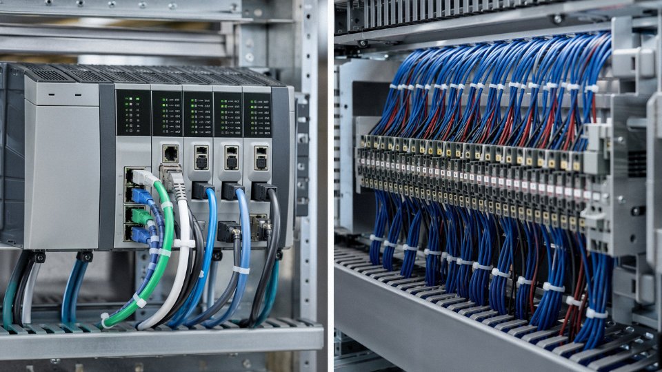
IO-Link Changes the Sensor Cable Equation
IO-Link (IEC 61131-9) is the quieter revolution. A three-wire unshielded cable — typically M12 connector, 24 VDC supply, and a single-wire switching/data signal — replaces what used to require a shielded multicore cable just to carry analog 4–20 mA plus a discrete output from a single smart sensor. That single cable carries digital measurement values, device parameters, and live diagnostic data. When a pressure sensor starts drifting, the IO-Link master can flag it before it causes a reject batch rather than after.
From a wiring installation standpoint, simpler cabling means faster commissioning, fewer termination errors, and dramatically reduced cable tray fill in dense sensor zones. For procurement, it means fewer SKUs and a more standardized cable spec across a machine family.
Hybrid Cables: One Pull, Two Functions
Hybrid constructions — power pairs and communication pairs sharing a single outer jacket with internal shielding between them — are gaining traction wherever cable tray space is tight or conduit entries are limited. The design challenge is real: without adequate inter-pair shielding, the switching noise from even a 24 VDC power conductor will corrupt the signal pairs. Well-engineered hybrid cables use individually shielded pairs or a foil barrier between the power bundle and the data bundle. Jinda produces hybrid cable constructions to customer specifications, including custom conductor counts, shield configurations, and LSZH jacket compounds — useful when a machine OEM needs a documented, repeatable cable spec that works across multiple installation sites internationally.
Hybrid power-and-communication cables require internal shielding between power and signal pairs to prevent noise coupling at the physical layer.True
Without separation shielding, conducted switching noise from DC power conductors induces voltage on adjacent signal pairs, degrading or disrupting digital communication — particularly at higher baud rates used in industrial Ethernet applications.
24 VDC PELV Is Now the Default
The shift from 120 VAC control circuits to 24 VDC PELV (Protective Extra Low Voltage) systems is essentially complete on new machinery in most markets. Shock hazard is lower, PLC I/O modules interface directly without interposing relays in most cases, and a single 24 VDC specification travels cleanly across CE, UL, and other compliance frameworks without the voltage-rating conflicts that 120 VAC creates in non-North American markets. Legacy plants running relay-logic 120 VAC circuits will keep them running for years — maintenance teams know them, and replacing them has a hard-to-justify ROI unless a broader control upgrade is underway.
Physical Security Comes Before Cybersecurity Software
As control wiring increasingly terminates at network-connected devices, the physical layer matters for security, not just signal integrity. Unlocked cabinets with open Ethernet ports are an access point regardless of how sophisticated the firewall configuration is. Locking enclosures, port-blocking covers on unused switch ports, and documented cable labeling that makes unauthorized connections visible are the unglamorous first line of defense. Software security layers are necessary but they assume the physical layer is controlled.
LSZH Specification Is No Longer Optional in Many Projects
Low smoke zero halogen cable is now a baseline specification on projects covered by EU construction products regulation, most transit infrastructure, data centers pursuing LEED or BREEAM certification, and increasingly, insurance underwriters with specific language in commercial property policies. The performance difference in a cable fire is not marginal — LSZH jackets reduce toxic gas and opaque smoke output substantially, giving evacuation time and limiting damage to adjacent equipment. Jinda’s LSZH control cable lines use halogen-free compound formulations compliant with IEC 60754 and IEC 61034, and those compounds are sourced with traceability documentation that project owners increasingly require at handover.
Managing the Transition Period in Real Procurement
Most operating plants are not greenfield. They are running legacy relay-logic hardwired panels in Building A while commissioning a new PROFINET-based line in Building B. That mixed environment creates a procurement problem: you need conventional multicore control cable, industrial Ethernet cable to IEC 61156 spec, IO-Link cordsets, and possibly hybrid constructions — sometimes for the same project phase. A fragmented supply chain across those categories creates version control headaches, delivery gaps, and documentation inconsistencies at factory acceptance. Working with a supplier who manufactures across all those cable families from a single production platform simplifies qualification, consolidates test documentation, and reduces the number of vendor audits a procurement team has to manage.