Specify the wrong cable structure for a buried distribution run and you will not find out immediately — you will find out eighteen months later when ground movement crushes the jacket, moisture tracks into the insulation, and a feeder trips at the worst possible shift. Replacing a direct-buried medium-voltage cable after the civil work is done can cost three to five times the original material price once you factor in excavation, lost production, and the emergency procurement premium that procurement managers know all too well. The global wire and cable market was already sitting around USD 225 billion in 2023 and is moving toward USD 300 billion by 2030, which means the range of available structures has expanded — and so has the room for a costly mismatch.
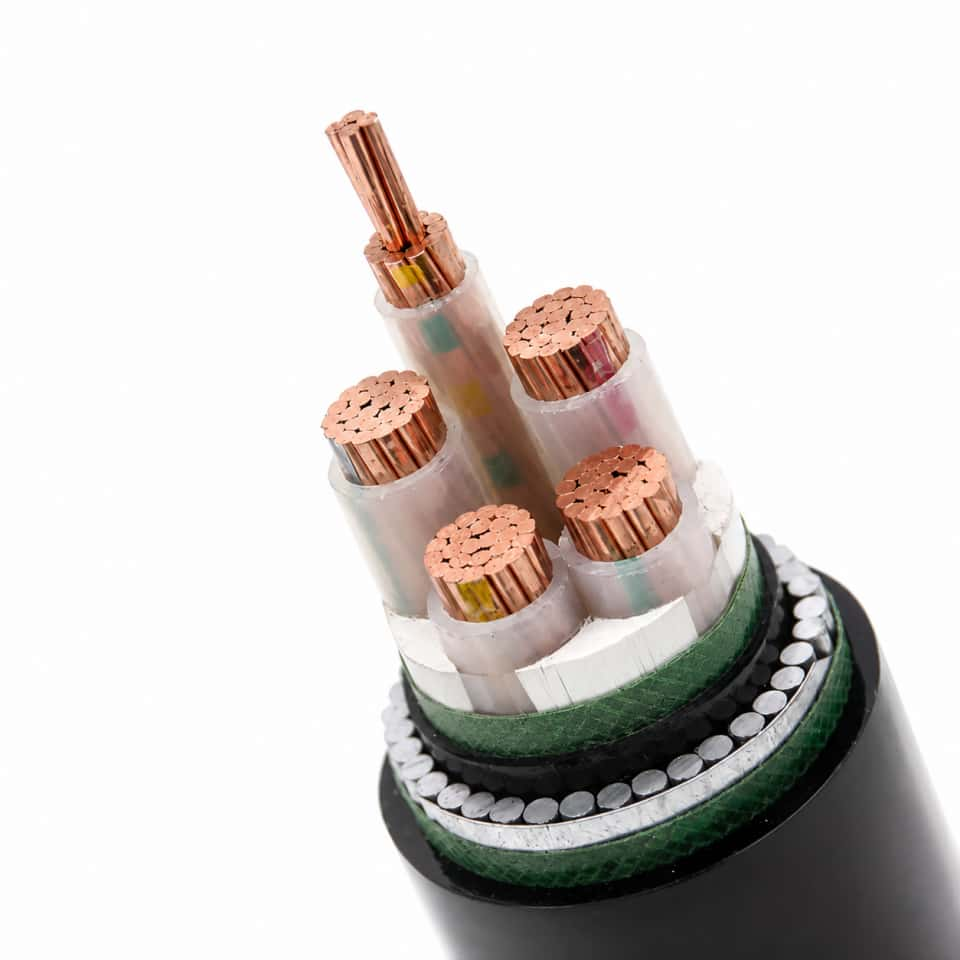
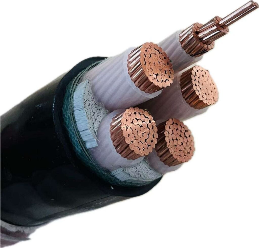
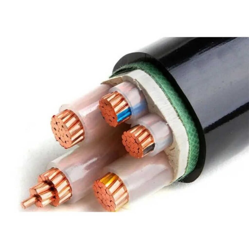
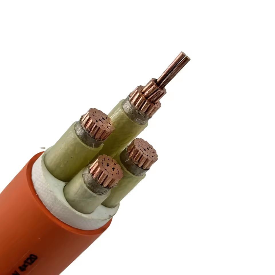
Cable structures fall into several distinct categories defined by how their conductors, insulation, shielding, and mechanical protection layers are assembled. The main types include solid and stranded conductor cables, single-core and multicore configurations, screened and unscreened designs, armored cables (SWA, AWA, and tape-armored variants), flexible and trailing cables, and high-voltage XLPE transmission cables. Each structure is engineered for a specific combination of installation method, fault-current duty, mechanical stress, and service environment.
What makes this genuinely complicated — and worth working through carefully — is that two cables can share the same voltage rating and conductor cross-section while performing completely differently in service, purely because of how their layers are built up. A 35 kV single-core XLPE cable installed in a cable tray on a petrochemical site has almost nothing in common structurally with a 35 kV cable pulled through a concrete duct under a road, even if the nameplate looks the same. The structure is the engineering decision.
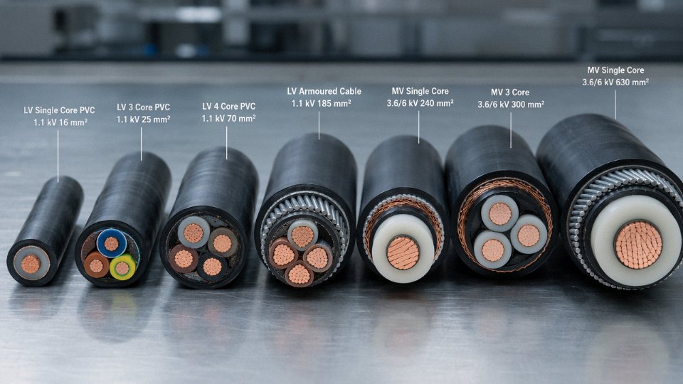
Conductor Architecture: Solid, Stranded, Compacted, and Segmental Designs
The conductor is where the electricity actually flows, so getting its construction wrong has immediate, measurable consequences — higher resistive losses, premature insulation damage from thermal cycling, or outright failure during installation when the cable cracks or kinks. Every other structural layer exists, in a sense, to protect this one.
Solid Conductors
Solid conductors are a single drawn wire, typically available from 1.5 mm² up to around 16 mm², though in practice most fixed-wiring applications stop at 10 mm² before contractors switch to stranded for handling reasons. Per IEC 60228 Class 1, the DC resistance of a solid conductor is marginally lower than an equivalent stranded design at the same cross-section because there’s no geometric inefficiency — no inter-wire gaps, no helical lay adding effective length. That small resistance advantage matters in densely packed residential distribution boards running at continuous rated current for years.
The limitation is flexibility. Solid conductors work well in conduit or trunking where the cable is laid once and stays put. Pull one around a tight radius repeatedly and you’ll work-harden the copper until it snaps. They have no place in anything that moves, vibrates, or gets re-routed during maintenance cycles.
Stranded Conductors
Stranding solves the flexibility problem by assembling multiple smaller wires in a concentric helical lay. IEC 60228 defines the main classes: Class 2 is concentric-lay stranded for fixed installations (the familiar 7-wire or 19-wire bundles), Class 5 is flexible, and Class 6 is extra-flexible — the kind used in portable tools, welding leads, and drag chains on automated machinery.
Wire count runs from 7 wires at small cross-sections up to 91 wires or more in larger flexible conductors. Shorter lay length increases flexibility but also increases the conductor’s effective length per meter and therefore its DC resistance slightly. At high frequencies, strand count and lay geometry influence skin-effect losses — the current crowds toward the outer surface of each wire, and a finer-wire, shorter-lay construction can actually worsen aggregate AC losses if not designed carefully. For most 50/60 Hz power cable applications this is a secondary concern, but it becomes relevant above roughly 1 kHz in variable-frequency drive (VFD) feeder cables.
Compacted and Shaped Stranded Conductors
Standard stranded conductors have a fill factor somewhere around 75–78% — the rest is air between wires. Compaction, done by rolling or drawing the stranded bundle through a die after stranding, collapses that void space and pushes the fill factor up to roughly 90%. The result is a conductor that’s 10–15% smaller in diameter than a non-compacted equivalent, which directly reduces the volume of insulation, bedding, and jacket material needed. On a 630 mm² or 1,000 mm² MV cable order of any real size, that material reduction is not trivial. Lead times on XLPE compound and the cable’s overall shipping weight both drop.
Shaped (or sector-shaped) conductors take this further in multicore designs — three-core cables especially — where trapezoidal or sector profiles nest together to reduce overall cable diameter compared to round compacted cores. Common in 11 kV and 33 kV distribution cables.
Segmental (Milliken) Conductors
Above roughly 1,000 mm², AC resistance diverges significantly from DC resistance because skin effect and proximity effect concentrate current in a thin annular zone at the conductor’s periphery. A solid or conventionally stranded conductor at 1,600 mm² or 2,500 mm² is, from an AC transmission standpoint, wasteful — you’re paying for copper that barely carries current.
The Milliken design addresses this by dividing the conductor into four, five, or six individual segments, each stranded and lightly insulated or separated by a semiconducting tape, then assembled and twisted together as a complete unit. Each segment is thin enough that skin effect within it is manageable, and the twisting of segments around the cable axis distributes proximity-effect losses more evenly. The AC resistance reduction compared to an equivalent non-segmented conductor can be meaningful enough to justify the added manufacturing complexity on any 110 kV–500 kV XLPE transmission cable.
Milliken conductor design reduces AC resistance in large cross-section HV cables compared to conventional stranded designs of the same cross-section.True
Segmentation limits skin-effect depth per segment and distributes proximity-effect losses through segment transposition, a well-documented principle in IEC and CIGRE transmission cable engineering literature.
Conductor Material: Copper vs. Aluminum Alloy
Electrolytic tough-pitch (ETP) copper runs at roughly 58 MS/m conductivity. Aluminum alloy 1350-H19 sits around 34–35 MS/m — about 60% of copper’s conductivity. To carry the same current, an aluminum conductor needs approximately 1.6 times the cross-sectional area, which partially offsets the weight advantage, but aluminum still comes out around 50–55% lighter than the copper equivalent. In overhead transmission, long submarine cable pulls, or any installation where pulling tension is a constraint, that weight saving is operationally significant.
The real-world complication is termination and corrosion. Aluminum forms a resistive oxide layer quickly; bi-metallic connections to copper busbars need proper transition lugs and anti-oxidant compound or you’ll see hot joints develop within a few years. In coastal or chemically aggressive environments, alloy selection and conductor coating matter more than conductivity percentages.
Jinda manufactures conductors from 1.5 mm² through 2,500 mm² in both ETP copper and aluminum alloy across its five production bases in China, with capacity scaled for bulk project supply at MV and HV ratings — the kind of volume that matters when you’re specifying a substation interconnection or a wind-farm export cable and need consistent conductor geometry across a long production run.
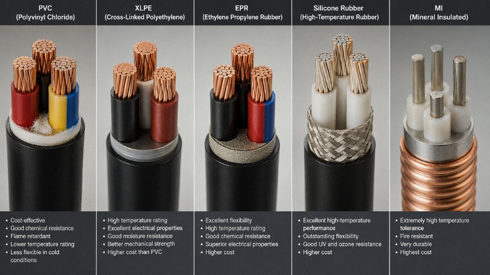
Insulation Systems: XLPE, PVC, EPR, LSZH, and Mineral Insulation Compared
The insulation layer is where most cable failures actually originate — not the conductor, not the armor. Get the insulation chemistry wrong for the environment, and you’re looking at premature dielectric breakdown, accelerated aging, or a fire that spreads instead of self-extinguishing. Each major insulation system has a distinct electrochemical profile, and understanding those differences is what separates a well-specified cable from an expensive mistake.
PVC: Workable, Cheap, but Know Its Limits
Polyvinyl chloride has dominated low-voltage wiring since the 1950s for obvious reasons: it’s inexpensive, easy to extrude, and mechanically tough enough for most building and light industrial applications up to 1 kV. Standard PVC runs at 70°C continuous; heat-resistant grades push to 90°C, which matters in panel wiring where ambient temperatures inside enclosures can climb well above 40°C in summer.
Volume resistivity sits around 10¹³ Ω·m — acceptable for LV but not competitive with XLPE at higher voltages. The real operational constraints are cold-temperature embrittlement (PVC gets genuinely brittle below about -15°C, which causes cracking during winter installation or in cold-store applications) and fire behavior. On ignition, PVC releases hydrogen chloride gas and generates dense black smoke. In a confined space — a cable basement, a ship’s corridor — that’s a serious hazard. For anything other than standard building wiring, procurement teams should at least ask the question before defaulting to PVC.
XLPE: The Workhorse of Medium and High Voltage
Cross-linked polyethylene dominates MV and HV cable markets globally, and for good reason. The cross-linking process — typically peroxide-initiated in continuously vulcanized (CV) lines for power cable, silane-based for lower-cost LV applications, or radiation-cured for specialized wire — converts thermoplastic PE into a thermoset network. That network eliminates the creep and deformation that thermoplastics suffer under sustained thermal load, which is exactly what kills cables at elevated operating temperatures.
XLPE runs continuously at 90°C conductor temperature, tolerates 250°C for short-circuit events, and has a dielectric constant of roughly 2.3 — low enough to keep capacitive losses and dielectric heating manageable across the full voltage range from 1 kV up to 500 kV. Conductor cross-sections in HV XLPE cables commonly range from 240 mm² to 2,500 mm², and individual cable segments can cover transmission distances of 50 km or more before jointing is required. At the top end of that voltage range, the quality of the insulation screen interface and the cleanliness of the XLPE compound itself become critical — even microscopic voids or contaminants become initiation sites for electrical treeing over time.
XLPE insulation does not flow or deform under sustained thermal load after cross-linking, unlike standard polyethylene.True
Cross-linking creates covalent C-C bonds between polymer chains, converting the thermoplastic structure into a three-dimensional thermoset network that resists creep even at elevated temperatures — this is the fundamental difference between XLPE and PE insulation.
EPR: The Flexible Solution for Harsh Environments
Ethylene propylene rubber trades some dielectric efficiency for outstanding mechanical flexibility and low-temperature performance. EPR stays pliable down to roughly -50°C, which makes it the standard choice for offshore platform cables, mining trailing cables, and shipboard installations where cables are constantly flexed, dragged, or exposed to seawater splash. Its dielectric constant runs around 3.0 — higher than XLPE, which increases capacitive charging current at higher voltages — so EPR is rarely specified above 33 kV except in specific niche applications. For flexible industrial cables in the 6–11 kV range operating in genuinely brutal mechanical conditions, it’s hard to beat.
LSZH: Mandated Where Evacuation Risk Drives the Specification
Low Smoke Zero Halogen compounds replace the halogenated polymer matrix with mineral filler systems — typically aluminum trihydrate (ATH) or magnesium dihydroxide (MDH) — that release water vapor on decomposition rather than toxic or corrosive gases. A properly formulated LSZH compound should achieve a limiting oxygen index above 28% and smoke density below 15% light transmission loss under IEC 60332-3-24 bundle fire test conditions.
Tunnels, metro systems, airports, data centers, and hospital corridors increasingly mandate LSZH by specification or local building code. The operational tradeoff is mechanical: LSZH compounds are generally stiffer and less abrasion-resistant than PVC, which can complicate installation in tight conduit runs. In practice, installers sometimes underestimate the pulling tension required and damage the outer sheath. Specifying the correct minimum bending radius on the installation drawing is not optional.
Mineral Insulation: When the Cable Must Survive the Fire
MICC (mineral insulated copper-clad) cables use compacted magnesium oxide powder inside a seamless copper or stainless steel tube as both the conductor sheath and the mechanical enclosure. MgO has essentially no organic content, so there’s nothing to burn. Continuous operating temperature reaches 250°C; fire survival rating extends to 1,000°C. These cables are specified for circuits that must keep operating during a fire — emergency lighting, fire pumps, hospital life-safety circuits, nuclear facility instrumentation.
The cost and installation complexity are significantly higher than any polymer-insulated cable. MICC cables require specialized termination fittings (Pyrotenax-style pot-and-seal assemblies are common) and are moisture-sensitive during installation — the MgO is hygroscopic, so open ends must be sealed immediately and terminations done correctly the first time. A failed termination in a nuclear application is not a minor event.
Comparative Specification Reference
| Insulation | Voltage Range | Continuous Temp. | Flexibility | Fire Performance | Moisture Resistance | Typical Application |
|---|---|---|---|---|---|---|
| PVC | Up to 1 kV | 70–90°C | Good | Poor (toxic smoke, HCl) | Moderate | Building wiring, LV panels |
| XLPE | 1 kV – 500 kV | 90°C | Moderate | Self-extinguishing grades available | Good (with screen/sheath) | MV/HV power transmission, distribution |
| EPR | Up to 33 kV (typically) | 90°C | Excellent | Moderate | Very good | Offshore, mining, shipboard, trailing cables |
| LSZH | Up to 1 kV (common); MV grades exist | 70–90°C | Moderate–stiff | Excellent (low smoke, no halogen) | Good | Tunnels, metros, hospitals, data centers |
| Mineral (MgO) | Up to 1 kV (standard); higher on request | 250°C continuous, 1,000°C fire survival | Poor (rigid) | Outstanding | Poor if unsealed | Fire-survival circuits, nuclear, high-rise life safety |
One thing worth stating plainly: these insulation systems are not interchangeable simply because the voltage rating overlaps. A cable specified for a metro tunnel must meet the smoke and toxicity requirements regardless of whether a PVC version would technically handle the voltage and current. Regulatory compliance and the actual failure mode in an emergency are part of the specification — not afterthoughts.
Shielding and Screening Structures: Tape, Braid, Concentric Wire, and Double-Layer Designs
The single most common specification error I see on procurement drawings is using “shielding” as a catch-all term without distinguishing what the shield is actually supposed to do. A copper tape screen on a 10 kV XLPE cable and a braided screen on a VFD cable are both called “shields” — they share almost no engineering function. Getting this wrong doesn’t just waste money; it causes relay misoperation, insulation failures, and in MV systems, potentially lethal fault conditions.
Electrical Shielding vs. Fault Current Screening: Two Different Jobs
In instrumentation and control cables, shielding exists to suppress electromagnetic interference — it intercepts capacitively and inductively coupled noise and drains it to a reference ground. The shield carries essentially no power current in normal operation. In medium-voltage power cables (roughly 6 kV and above), the metallic screen serves a fundamentally different purpose: it must carry capacitive charging current continuously, and during a phase-to-earth fault, it becomes the return path for fault current — sometimes for hundreds of milliseconds until the protection clears. Specifying a 0.08 mm copper tape screen on a 6.6 kV cable running through a system with a 2 kA earth fault level is an undersized design that will fail thermally on first fault. The tape will rupture, the insulation will be damaged, and you’ll be looking at a full cable replacement rather than a fault-clearance event.
Copper Tape Screens in MV Cables
Copper tape shielding is the dominant screen construction for 6 kV–35 kV XLPE cables. Tape thickness typically runs 0.05–0.10 mm depending on voltage class and the manufacturer’s standard; the exact value affects both the uniformity of field distribution around the insulation and the screen’s continuous current capacity. IEC 60502-2 requires a minimum overlap of 15% between adjacent tape turns — this matters because a gap in the tape creates a local electric field concentration that initiates treeing in the XLPE over time. Short-circuit current capacity is modest: a standard single-tape screen handles roughly 150–250 A for one second before the copper temperature exceeds the thermal limit, exact figure depending on tape cross-section and initial conductor temperature. For systems where fault clearance is slow or fault levels are high, a single tape screen is inadequate on its own.
Copper Wire Screens and Earth Continuity Conductors
Where fault current capacity is the controlling constraint, a concentric copper wire screen becomes the correct choice. Wire screen cross-sections on MV cables typically range from 16 mm² to 95 mm², and the selection is straightforward in principle: calculate the thermal energy the screen must absorb (I²t, where I is the prospective earth fault current and t is the maximum fault clearance time), then select a cross-section that keeps the copper below 200 °C — the limit typically cited for short-circuit conditions per IEC 60949. Many MV cable systems also incorporate an Earth Continuity Conductor (ECC), a separate copper conductor laid alongside or integrated into the screen construction, which supplements fault current capacity without increasing the overall cable diameter as much as upsizing the wire screen alone.
IEC 60502-2 requires a minimum copper tape overlap of 15% in the metallic screen of MV XLPE cables to ensure continuous field uniformity.True
IEC 60502-2 Clause 12 specifies construction requirements for metallic screens including minimum overlap percentage for tape screens to prevent field concentration and maintain screen continuity.
Braided Shielding for Flexible and High-Frequency Applications
Braided shields — copper or tinned copper wire woven at a coverage angle optimized for the target frequency range — are the standard choice for flexible instrumentation cables, thermocouple extension leads, and particularly for VFD (variable frequency drive) motor cables, where the inverter switching generates common-mode noise across a broad frequency spectrum. Coverage percentage is the critical parameter: at 85% coverage, high-frequency attenuation is noticeably weaker than at 95%, particularly above 100 kHz. In practice, most serious VFD cable specifications call for ≥93–95% braid coverage combined with a drain wire, because incomplete coverage leaves gaps that act as slot antennas at the switching frequency harmonics. A tinned copper braid is worth the small premium in humid or chemically aggressive environments — bare copper oxidizes, and oxide layer resistance degrades shielding effectiveness over years of service.
Double-Layer Screening in Instrumentation Cables
Multi-pair and multi-triad instrumentation cables for process plants routinely carry HART, Foundation Fieldbus, Profibus PA, or plain 4–20 mA analog signals through cable runs that pass near variable-speed drives, switchgear, and bus ducts. A single overall foil screen is usually not enough. The standard construction for demanding process environments uses individual pair or triad foil screens — aluminum-polyester tape bonded to a drain wire — plus an overall copper braid. This combination, when properly terminated at both ends (or single-point for analog loops, depending on the grounding scheme), achieves shielding effectiveness above 90 dB at frequencies above 1 MHz. That’s the range where VFD and SMPS interference lives. Without adequate shielding effectiveness, a 4–20 mA signal on a 100-meter run near a 75 kW drive becomes unreliable — the induced noise floor can exceed the signal resolution the transmitter is trying to achieve.
Semiconducting Layers: The Hidden Structural Element in HV Cables
Above roughly 6 kV, cables require something that isn’t obvious from a cross-section drawing: inner and outer semiconducting compound layers sandwiching the XLPE insulation. The stranded conductor surface is geometrically irregular — the interstices between wires create microscopic voids where the electric field intensifies dramatically. Without the inner semiconducting layer (a carbon-loaded compound extruded directly over the conductor), those field concentrations would initiate partial discharge in the insulation within months. The outer semiconducting screen, applied over the XLPE surface before the metallic screen, serves the same function in reverse: it creates a smooth, equipotential interface between insulation and screen, eliminating field concentration caused by any surface irregularity in the XLPE itself. IEC 60840 (for cables above 30 kV) sets the volume resistivity of these compounds at ≤1,000 Ω·m — a tightly controlled parameter that must remain stable across the cable’s operating temperature range. Getting this wrong in manufacturing, through incorrect compound selection or processing temperature deviations, produces a cable that passes factory acceptance tests but develops partial discharge and premature failure in service.
The semiconducting layers add process complexity and material cost, which is why some commodity MV cable suppliers minimize them or use substandard compound. It’s worth specifying the compound volume resistivity limit explicitly in your technical data sheet rather than simply citing the standard by number — it forces the manufacturer to demonstrate compliance rather than assume it.
Armoring Structures: SWA, STA, AWA, DSTA, and Wire Braid Armor for Mechanical Protection
Armor is the layer most engineers take for granted until something fails. A cable pulled through rocky backfill without adequate crush resistance, or a single-core cable armored with steel wire instead of aluminum — both are specification errors that show up months or years later as insulation breakdown, nuisance trips, or worse.
Steel Wire Armored (SWA)
SWA is the workhorse of medium-voltage buried distribution. Individual galvanized steel wires are wound helically around the cable’s bedding layer at a lay angle of roughly 40°–55°; tighter angles improve tensile strength, shallower angles improve flexibility. IEC 60502-1 sets the minimum UTS for each wire at 350 N/mm², and in practice a properly made SWA cable achieves crush resistance in the 4,000–5,000 N/100 mm range — the exact figure depends on wire diameter, lay angle, and whether the cable uses a round or flat wire variant. That’s enough for direct burial at depths to around 1,200 mm in cohesive soils (IEC Type D), though anyone burying in loose gravelly fill or under a road crossing should still specify a duct or a concrete tile above the cable. SWA handles tensile loads well enough for aerial self-supporting runs on short spans and for installation by cable-pulling winch through long conduit runs.
Steel Tape Armored (STA)
Two overlapping steel tapes wound helically replace the wire layer in STA construction. Lighter, cheaper, and faster to manufacture than SWA — but the trade-off is real. STA provides solid radial crush resistance and good protection against rodent damage; tensile strength is significantly lower, typically 40–60% of an equivalent SWA cable. That’s fine for indoor tray runs, short duct pulls, and installations where the cable will never see axial tension. Specifying STA on a cable that needs to be suspended or pulled long distances is a common procurement mistake driven by price pressure.
Aluminum Wire Armored (AWA) — and Why It Matters for Single-Core Cables
This is where physics forces the engineer’s hand. In a three-core cable, the magnetic fields from all three conductors largely cancel each other, so steel armor experiences minimal net induced current. In a single-core cable carrying AC, the alternating magnetic field of the single conductor threads through the steel armor as a transformer core, inducing circulating currents and hysteresis losses. At 95 mm² and above, those losses in steel armor can reach 15–30% of the conductor’s own I²R losses — wasted as heat, which derate the cable and raises operating cost continuously over its service life. IEC 60502-1 requires non-magnetic armor (aluminum wire or tape) for single-core cables above 16 mm² precisely because of this.
AWA uses the same helical winding geometry as SWA, but the individual wires are aluminum alloy. Mechanical performance is somewhat lower in UTS terms, but eddy current and hysteresis losses drop to negligible levels.
Steel wire armor on single-core AC cables above 16 mm² causes significant induced losses that can derate the cable and raise operating temperatures.True
IEC 60502-1 mandates non-magnetic armor for single-core cables above 16 mm² to prevent magnetic hysteresis and eddy current losses in ferromagnetic armor, which can account for a meaningful fraction of total cable losses in service.
Double Armor Designs: DSTA and DSWA
Submarine cables and direct-buried cables in aggressive or high-pressure environments step up to double-layer constructions. In DSWA, two layers of steel wire are applied with opposite helical directions — one layer left-lay, one right-lay. That counter-helical geometry matters: during cable laying or pulling, a single wire-armor layer tends to torque under tension. The opposing lay angles neutralize that torsional couple, preventing the cable from unscrewing itself or kinking. DSTA does the same with tape layers and is common in riverbed crossings or shallow coastal runs where hydrostatic pressure is moderate but soil abrasion is severe.
Interlocked and Corrugated Aluminum Sheath Armor
The North American market, particularly for MC cable and industrial tray cable governed by UL 4, uses a different approach. Interlocked aluminum armor (IA) consists of formed aluminum strip folded into an interlocking helical profile — flexible, relatively lightweight, and compliant with NEC installations in exposed industrial environments. Corrugated aluminum sheath construction takes this further by combining the moisture barrier and the mechanical protection into one continuous corrugated aluminum tube, either welded longitudinally or formed and corrugated over the insulated cores. It’s genuinely elegant engineering: one layer does the job of two. Common in North American HV cable, petrochemical plant cable, and any application where moisture ingress through the armor interstices of SWA would be a problem.
Wire Braid Armor for Flexible Applications
Drag-chain cables, robotic arm cables, and mine trailing cables operate in a completely different mechanical regime. Static crush and burial depth are irrelevant; what matters is cyclic bending fatigue, torsion resistance, and the ability to survive millions of flex cycles without the armor becoming a source of wire fatigue fractures that then cut into the insulation.
Braided armor — bronze, galvanized steel, or stainless steel depending on the corrosion environment — is applied at a braid angle close to 54°44′, which is the neutral angle where the braid geometry neither elongates nor compresses under axial load. At that angle, the braid responds to both tension and compression by shear deformation rather than wire stretching, preserving mechanical integrity across the flex cycle. A braid angle even 5° off neutral measurably reduces flex life. Bronze braid is preferred in marine and offshore flexible hose assemblies; stainless steel for high-temperature or chemically aggressive environments; galvanized steel where cost drives specification and the environment is benign.
| Armor Type | Typical Crush Resistance | Tensile Suitability | Key Application |
|---|---|---|---|
| SWA | 4,000–5,000 N/100 mm | High | Direct burial, duct, aerial (MV) |
| STA | Moderate (radial only) | Low | Indoor tray, short duct |
| AWA | Comparable to SWA | Medium–High | Single-core AC cables >16 mm² |
| DSTA/DSWA | Higher than single-layer | High + torsion-neutral | Submarine, aggressive burial |
| Interlocked/Corrugated Al | Moderate | Low–Medium | MC cable, NEC tray, moisture-critical |
| Wire Braid | Low (radial) | Moderate | Drag-chain, robotic, trailing |
Getting armor type wrong is rarely immediately visible. The failure shows up after the cable has been installed, backfilled, and energized — usually at the worst possible time.
Outer Jacket and Sheathing Materials: PVC, PE, PUR, Neoprene, and LSZH in Harsh Environments
The jacket is the layer most people touch and the one they tend to underspecify. That’s a mistake. Wrong jacket material means premature cracking in a cold climate, swelling and delamination in an oily machine environment, or — in a congested tunnel — toxic smoke that turns an electrical fault into a mass casualty event. The conductor and insulation determine electrical performance; the jacket determines whether the cable survives long enough to deliver it.
PVC Outer Sheath (Type ST1/ST2 per IEC 60502)
PVC remains the global default for good reasons: it’s cheap, it processes easily on standard extrusion lines, and ST2 compound gives adequate resistance to weathering, dilute acids, and many petroleum-based oils. Temperature range sits between roughly -15°C and +70°C continuous — workable across most temperate industrial sites. The problem shows up at the extremes. Below about -10°C a standard ST1 sheath gets brittle enough that installers cracking it off a drum in a January morning pull can split it without even noticing. And in a fire, PVC generates hydrogen chloride gas and dense black smoke. That’s not a regulatory abstraction; it’s the reason most European rail and tunnel projects banned PVC jackets on new cable installations years ago.
For outdoor industrial switchyards, underground duct runs, and general power distribution where personnel evacuation isn’t a design constraint, PVC is still entirely appropriate. Don’t let someone talk you into a premium sheath where ST2 does the job.
Polyethylene (PE) Sheath
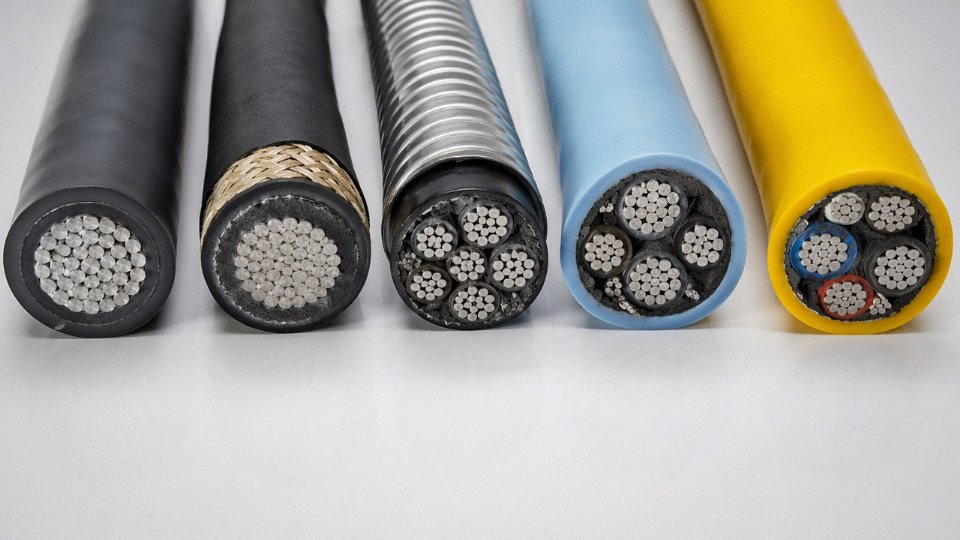
PE outperforms PVC on two specific metrics that matter a lot for buried and submarine cables: moisture vapor transmission rate and low-temperature flexibility. Carbon-black-loaded HD-PE (>2.5% CB by mass per ASTM D1603) resists UV degradation effectively and stays flexible down to around -40°C — relevant if you’re routing cable in northern Canada, Scandinavia, or high-altitude sites. Direct-buried MV and HV XLPE cables almost universally use PE as the outer sheath precisely because long-term moisture ingress into the insulation screen is the primary aging mechanism. PE slows that ingress significantly compared to PVC. For submarine cables, PE is essentially the only sensible choice for the outer serving over the armor wires.
Polyurethane (PUR) Sheath
PUR is the drag-chain engineer’s sheath. Abrasion loss per DIN 53516 runs below 60 mm³ for good PUR compounds — roughly three to five times better than standard PVC in the same test. It handles hydraulic oils, cutting fluids, and aviation-grade lubricants without swelling or surface cracking, and cold-flex ratings typically reach -50°C. In robotic welding cells or CNC machine tool environments where a cable gets flexed several million cycles over its service life while lying in metal swarf soaked in coolant, PUR pays for itself fast. The cost premium over PVC is real — expect to pay noticeably more per meter — but the replacement and downtime cost of a sheath failure inside a live production cell is almost always worse.
Offshore subsea umbilicals also use PUR for the outer sheath over the bundled hose and cable cores, because polyurethane handles the combination of seawater immersion, mechanical abrasion against the seabed, and hydrocarbon contamination better than anything comparably cost-effective.
Chlorosulfonated Polyethylene (CSPE/Hypalon) and Neoprene (CR)
These are the workhorses for portable power cables in genuinely tough environments: open-cast mining, submersible pump drops, trailing welding leads. Neoprene (polychloroprene, CR) compound typically achieves tensile strength in the 10–14 MPa range with elongation at break around 300–400%, which gives the cable enough mechanical toughness to survive being run over by a forklift — occasionally. More importantly, both CR and CSPE resist ozone cracking, which quietly destroys standard rubber sheaths outdoors within a few years. CSPE handles continuous service temperatures up to around 90°C and offers better flame retardance than straight neoprene.
Neither compound is cheap to process, and CSPE (sold historically under the Hypalon trade name) has become harder to source in some markets since DuPont exited that business. In practice, many manufacturers now offer EPDM/CR blends as a substitute — check the actual compound spec, not just the trade name.
LSZH/LSOH Outer Sheaths
Low-smoke zero-halogen compounds are mandatory in any installation where fire evacuation time matters: passenger rail rolling stock, underground stations, road tunnels, offshore topsides, data centers, and public buildings per IEC 60332-1 and -3. The chemistry is straightforward — ATH (aluminum trihydrate) filler releases water vapor on combustion, suppressing flame spread and diluting smoke — but the mechanical trade-off is real and often glossed over.
ATH-filled LSZH sheath compounds typically exhibit lower tensile strength (around 10 MPa) compared to standard PVC sheath (around 15 MPa) at equivalent wall thickness.True
ATH filler loading required for flame performance dilutes the polymer matrix, reducing tensile and tear strength. This is documented in IEC 60227 and 60245 compound performance tables and is a known trade-off when specifying LSZH cables.
That strength gap means LSZH cables need more careful drum handling, larger bending radii during installation, and more support cleats in vertical runs. Installers who treat LSZH the same as PVC during a rushed cable pull will damage the sheath without knowing it. Some manufacturers use an inner glass-fiber braid sub-layer under the LSZH oversheath to partially compensate — worth asking about for long vertical drops or tight-conduit pulls.
Specialty Sheath Additives
Rodent damage kills more direct-buried cables in agricultural and tropical regions than most people admit. Capsaicin-based deterrent compounds blended into the outer sheath show mixed field results — the evidence is genuinely inconsistent, and I wouldn’t rely on chemistry alone in a rodent-heavy environment. A mechanical sub-layer of glass-fiber braid or an inner steel tape is more reliable. Anti-termite formulations (typically incorporating specific biocide compounds compliant with local environmental regulations) matter in sub-Saharan Africa, South and Southeast Asia, and northern Australia. Anti-tracking compounds prevent carbon tracking along the outer sheath surface near high-voltage terminations or on cables routed close to overhead lines — relevant for MV cables on overhead racks in surge-prone coastal industrial sites.
Getting the jacket specification right is, honestly, one of the cheaper decisions in a cable procurement. The material cost difference between PVC and PUR on a 500-meter run is a fraction of one day’s production downtime.
Complete Cable Family Structures: Power, Control, Instrumentation, Flexible, and Submarine Cables Disassembled
By the time you’ve worked through conductor geometry, insulation chemistry, shielding design, armor options, and jacket materials as separate topics, the natural question is: how do all those layers actually stack in a real cable? The answer varies significantly by cable family, and getting the stack wrong — even one layer misspecified — can mean premature failure, a rejected factory acceptance test, or a procurement dispute six months into a project.
Low-Voltage Power Cable: 4-Core 185 mm² XLPE/SWA/PVC, 0.6/1 kV (IEC 60502-1)
Start from the center outward. Each of the four cores carries a Class 2 stranded aluminum conductor — at 185 mm², you’re typically looking at 37 wires laid in concentric layers, giving a nominal conductor diameter around 15–16 mm depending on compaction. Aluminum is chosen here purely on weight-to-cost grounds for distribution feeders; the conductivity penalty is real (roughly 60% of copper by conductivity), but the economics usually win on runs over 50 m. Each conductor gets XLPE insulation extruded to around 0.9–1.0 mm wall thickness, color-coded to IEC 60304. Three-phase cores plus a reduced neutral — common on European LV distribution — are laid up together with PVC fillers pressed into the interstices to round out the assembly before bedding.
The PVC inner bedding (roughly 1.4–1.8 mm) exists to protect the insulation cores from armor wire indentation during installation tension. This layer gets skipped or thinned by some manufacturers trying to cut material cost, and you will see it in field failures — small indentations in the XLPE that eventually become partial discharge sites. Galvanized steel wire armor sits over the bedding, and for a 185 mm² four-core cable the wire diameter is typically 1.6–2.0 mm. The PVC outer sheath finishes the construction at around 2.0–2.5 mm.
Medium-Voltage Single-Core Cable: 12/20 kV XLPE/Cu Screen/PE (IEC 60502-2)
This is where manufacturing process discipline matters most. The copper conductor (Class 2 stranded, or compacted for larger cross-sections) receives a triple-extruded insulation system in a single continuous pass: inner semiconducting layer, XLPE insulation body, outer semiconducting layer. All three extruded simultaneously. That’s not a marketing claim — it’s the only practical way to guarantee void-free interfaces between layers, because any separate extrusion step introduces the risk of surface contamination or micro-gaps that become partial discharge inception points at 12 kV and above.
Over the outer semiconducting layer, copper wire screen (helically applied, with a counter-helix copper tape in many designs) provides fault current return path and electrostatic screening. PE outer sheath, typically 2.5–3.5 mm, closes the construction. PE is preferred over PVC at MV for its lower dielectric constant and better moisture resistance over multi-decade service life.
Multicore Control Cable: Up to 48-Core PVC/SWA (450/750 V, IEC 60228 Class 2)
Core counts run from 2 to 48 in standard production; beyond that, you’re usually into custom territory. Solid copper conductors are common in smaller sizes (1.0–1.5 mm²) for cost and dimensional stability; stranded for 2.5 mm² and up where some flexibility is needed during panel wiring. The lay length of the core assembly matters more than most procurement specs acknowledge — tighter lay improves flexibility and reduces cross-talk between parallel signal cores, but increases cable diameter and material consumption, so there’s a genuine engineering trade-off to balance against the application’s vibration and routing requirements.
SWA over PVC inner sheath gives mechanical protection and an earth return path. One operational note: on multi-core control cables running mixed signal and power control cores in the same bundle, always verify that the design separates high-current switching circuits from low-level signal cores physically within the lay-up, not just by insulation color.
Instrumentation Cable: Individually and Overall Screened, LSZH, 300/500 V
The distinguishing feature is the cascaded screening architecture. Each twisted pair or triad carries its own aluminum-polyester foil screen with a drain wire — the drain wire is the practical termination point for the individual screen, and its gauge (typically 0.5–1.0 mm² bare copper) determines how much screen drain current it can carry before heating. An overall braid screen sits outside the assembled pairs, typically copper braid at 85–95% optical coverage.
For RS-485 and similar differential signaling, characteristic impedance control around 120 Ω requires tight control of pair geometry: conductor diameter, twist pitch, and insulation wall thickness all feed into the impedance calculation. Capacitance balance — the difference in capacitance between each conductor and screen — should be below roughly 100–150 pF/m difference for clean differential signal transmission over runs beyond 300 m. LSZH inner and outer sheaths are standard in any installation where smoke toxicity matters: offshore platforms, tunnels, data centers, public infrastructure.
Submarine Power Cable: 66–220 kV Three-Core XLPE with Integrated Fiber Optic (CIGRE TB 623)
The construction complexity here is genuinely different from land cable. Copper Milliken conductors (typically five keystone-shaped segments, individually insulated to suppress skin effect losses at the conductor surface above roughly 500 mm²) carry the power. Triple-extruded XLPE insulation with semiconducting layers, as described for MV cable, but to significantly higher dimensional tolerances given the voltage stress levels involved.
The lead alloy sheath — not PE, not PVC — is the critical moisture barrier. Submarine cable sits in a thermodynamic environment where moisture ingress into the XLPE over decades is the primary aging mechanism; lead provides a diffusion barrier that polymeric sheaths simply cannot match at 30–40 year design lives. Bitumen-impregnated polypropylene fiber bedding cushions the armor and resists marine biological fouling. Galvanized steel wire armor with PP serving closes the construction.
The integrated fiber optic unit, typically two to six single-mode fibers in a stainless steel loose tube embedded in the cable interstices, enables Distributed Temperature Sensing along the full cable route. DTS can detect hotspot temperatures within ±1–2°C at spatial resolution of around 1–2 m, allowing real-time ampacity management and early fault precursor identification — practically useful on cables where unplanned repair costs run into the millions.
Flexible Trailing and Drag-Chain Cable: H07RN-F per IEC 60245
Fine-wire stranded copper, IEC 60228 Class 5 or 6, is the foundation — Class 6 for robotic applications where torsional flex cycles matter. EPR insulation handles the flex cycles better than PVC, which work-hardens and cracks at the conductor-insulation interface within thousands of cycles under tight bending. Neoprene or PUR outer sheath selection depends on environment: PUR for oil and abrasion resistance in drag chains and machine tools, neoprene where flame retardancy and ozone resistance are priorities.
Minimum bending radius is not a single number — it depends on whether the cable is moving or static. Trailing cable in dynamic service: typically 4× OD continuous, 7.5× OD for a drag-chain installation. For robotic applications requiring torsional qualification, the standard test is ±180° per meter twist over 1 million cycles minimum; cables that pass this usually carry a documented test certificate, and you should ask for it.
Three-layer co-extrusion of semiconducting/XLPE/semiconducting layers in MV and HV cables eliminates interface voids that would otherwise cause partial discharge failures.True
Triple co-extrusion is a well-established manufacturing requirement in IEC 60502-2 and IEC 60840 for cables above 3.6/6 kV. Void-free interfaces are critical because partial discharges at even sub-millimeter voids under high electric field stress degrade XLPE progressively, leading to treeing and eventual insulation breakdown. This is documented in IEC technical literature and is standard quality assurance practice among serious MV/HV cable manufacturers.
Fire-Resistant and Flame-Retardant Cable Structures: Circuit Integrity Under Extreme Conditions
These two terms get used interchangeably on procurement specs all the time, and that mistake has real consequences. A flame-retardant (FR) cable is engineered to self-extinguish — it limits fire propagation along its own length, but once the insulation burns through, the circuit is gone. A fire-resistant cable is a fundamentally different structural proposition: it keeps the circuit alive while the fire is happening, for a defined period, under a defined temperature. Getting these confused on a hospital emergency power circuit or a tunnel smoke-extraction system is not a paperwork error. It is a life-safety failure.
The regulatory distinction is codified in IEC 60331, BS 6387, and EN 50200. None of these standards overlap cleanly, which frustrates procurement teams working across multiple jurisdictions — more on that below.
The Mica Tape Layer: Where the Real Work Happens
The structural heart of any fire-resistant cable is the mica tape wrap applied over each conductor or over the assembled core. Glass-fiber-backed mica tape, typically 0.1–0.2 mm thick depending on the voltage rating and target survival time, is wound at roughly 50% overlap in a single layer — or double-wrapped for higher-integrity applications. The overlap percentage matters more than most engineers realize. At 50% overlap, every point on the conductor is covered by two tape layers; drop that to 30% and you introduce single-coverage zones that can fail first under thermal shock.
When the polymer binder in the tape burns off at temperatures above roughly 500°C, the mica platelet structure consolidates into something approaching a ceramic sleeve. It is fragile — you can crack it by rough handling after a fire test — but it maintains dielectric continuity at 750°C–950°C well enough to satisfy rated voltage and current without a disruptive discharge. Double mica wrapping, while adding 0.3–0.6 mm to the cable’s overall diameter, is worth specifying wherever circuit survival beyond 90 minutes is required or where mechanical shock during the fire event is expected.

IEC 60331 and BS 6387: What the Test Actually Involves
IEC 60331-21 (for cable ≤20 mm overall diameter), -23, and -25 apply a 750°C ±40°C flame to the cable for 90 minutes while it carries rated voltage and current. Pass criteria is zero disruptive discharge — no short circuit, no earth fault, no over-current trip. Thermocouples are positioned at the flame midpoint and at specified distances away to verify temperature uniformity. The cable is energized throughout; a monitoring circuit triggers failure the moment continuity breaks.
BS 6387 goes further by layering environmental abuse onto the thermal test. Category C is the straight flame test at 950°C. Category W adds a cold water spray during the fire exposure — simulating sprinkler activation. Category Z adds mechanical shock by striking the cable with a weighted rod at intervals during the test. A cable rated CWZ has survived all three simultaneously, which is why BS 6387 CWZ is the benchmark specification on projects in the Gulf, Hong Kong, and much of Southeast Asia.
IEC 60331 and BS 6387 CWZ test a cable under different simultaneous stresses and are not interchangeable certifications.True
IEC 60331 applies flame only; BS 6387 Category W adds water spray and Category Z adds mechanical shock during the same fire exposure. A cable certified to IEC 60331 alone has not been tested under combined fire-plus-water-plus-shock conditions.
EN 50200 PH120 and Armored Fire-Resistant Structures
EN 50200 is the structural certification that EU building codes actually reference for emergency lighting circuits, fire alarm wiring, and smoke extraction motor feeds. PH120 requires 830°C ±40°C for 120 minutes plus repeated mechanical shock — a standard that eliminates a lot of cables that pass the easier tests. Armored versions, required in installations where cable routes are shared with general wiring, add a steel wire braid or glass-fiber braid over the mica layer. The braid serves two purposes: it provides pull-through resistance in trunking, and it limits the mica sleeve’s tendency to fragment under the shock impacts during the test protocol.
The LSZH-FR Combined Structure: A Genuinely Difficult Engineering Problem
Specifying a single cable that simultaneously meets IEC 60331 fire resistance, IEC 60332-3 bunch flame propagation, low smoke emission, and zero halogen content is increasingly common on metro, airport, and data center projects. The structural challenge is not the material selection — mica tape, XLPE or silicone insulation, LSZH compound outer sheath — it is the installation bending radius. Mica tape is brittle. Install the cable around a 4D bend during pulling, and you can crack the mica wrap before a flame ever touches it. In practice, LSZH-FR cables need tighter handling supervision on site than standard power cables, and the minimum bending radius specified in the data sheet should be treated as a hard limit, not a suggestion.
Jinda manufactures IEC 60331-certified fire-resistant cables — including LSZH-FR combined structures — for infrastructure projects across the Middle East, Southeast Asia, and Africa, with test documentation from CESI, Intertek, SGS, and equivalent accredited laboratories. Local authority approval requirements vary significantly by country; Jinda’s technical team routinely supports customers through the submission process.
Frequently Asked Questions About Cable Structures
Engineers and procurement managers run into the same structural specification problems repeatedly — often at the worst possible moment, like mid-tender or after a cable has already been installed. These answers go beyond definitions.
Does it matter whether I specify SWA or AWA for single-core cables?
It matters enormously. SWA (steel wire armor) uses galvanized steel wires; AWA (aluminum wire armor) uses aluminum. For multi-core cables and DC single-core cables, SWA is perfectly acceptable. The problem arises with single-core AC cables above roughly 16 mm² conductor cross-section: the alternating magnetic field from a single-core AC conductor induces circulating eddy currents in any ferromagnetic armor surrounding it. Steel armor on a single-core AC cable will heat continuously — not because of overload, but because of the armor’s own magnetic losses. In practice this wastes energy, accelerates insulation aging, and can cause localized overheating at cleats or joints. AWA breaks that magnetic circuit. Specifying SWA on a 240 mm² single-core 11 kV AC cable is a real mistake that gets made more often than it should, usually when procurement teams copy a multi-core schedule without reading the footnotes.
Can I run a 70°C PVC cable in an 80°C ambient environment?
No. The current-carrying capacity values in IEC 60364-5-52 assume a reference ambient — typically 30°C in air, 20°C for ground installation. The conductor temperature rating represents the maximum permissible conductor temperature, not headroom above ambient. If ambient is already 80°C and your cable is rated 70°C, the conductor is thermally stressed before you connect a single amp. You either upgrade to 90°C XLPE insulation or apply a derating factor so severe that the cable becomes uneconomically oversized. Hot process areas, boiler houses, near furnace exhausts — these catch people out regularly.
What does triple extrusion mean, and why does it affect cable reliability?
Triple co-extrusion (sometimes called three-layer co-extrusion) deposits the inner semiconducting layer, XLPE insulation, and outer semiconducting layer in a single continuous pass through one triple crosshead die. The layers bond at molecular level while still molten. Any process that applies these layers sequentially — even with short time gaps — risks microscopic voids or contamination at the semiconductor-insulation interface. Those voids become partial discharge sites under voltage stress, and partial discharge is the primary mechanism of long-term insulation degradation in medium- and high-voltage cables. For cables at 6 kV and above, triple extrusion is not a marketing claim; it is a structural requirement. Ask your supplier for process documentation, not just a spec sheet.
How do I size the copper wire screen for an 11 kV cable?
Screen cross-section is an earth fault current calculation, not a guesswork item. Use the adiabatic formula from IEC 60949:
A = I × √t / k
Where A is screen cross-section in mm², I is the maximum earth fault current in amps, t is the protective relay clearance time in seconds, and k = 143 for copper screen. If your network delivers 8 kA fault current and your upstream protection clears in 0.5 s, you need at minimum A = 8,000 × √0.5 / 143 ≈ 39.5 mm². Round up and add a margin for uncertainty in clearance time. Under-specified screens fail catastrophically at the fault location — they burn open, leaving the cable energized with no fault path.
The adiabatic formula A = I×√t / k with k=143 for copper screens is specified in IEC 60949 for short-circuit temperature rise calculations.True
IEC 60949 'Calculation of thermally permissible short-circuit currents' defines this formula and the k-factor values for various conductor and screen materials, including k=143 for copper.
Is LSZH always the right choice for outer sheaths?
Not always — and defaulting to LSZH everywhere is a procurement habit worth questioning. LSZH compounds sacrifice tensile strength and abrasion resistance compared to standard PVC or PE. They cost more. In a tunnel, metro, offshore accommodation module, or any enclosed space where smoke and halogen gas evacuation is difficult, LSZH is clearly the correct call — the structural tradeoff is worth it. For outdoor direct-buried cables, cable tray in open industrial plants, or installations where mechanical durability matters more than smoke behavior, PE or PVC sheaths typically outperform LSZH and cost 15–30% less depending on compound grade and wall thickness. Specify for the actual installation environment, not the easiest default.
What structure does a VFD cable actually need?
Variable frequency drive cables are a category where under-specified cable causes measurable production losses through bearing failures, EMI interference with controls, and insulation breakdown from voltage spikes. The structural checklist: symmetrical three-phase conductor arrangement (this reduces EMI at the source); a 360° copper braid or combined foil-plus-braid shield with coverage of 85% or better to contain high-frequency harmonics that can reach 10 MHz or higher; XLPE or EPR insulation capable of handling voltage spikes up to roughly 3× nominal due to the reflected wave effect on long cable runs; and a PUR outer sheath for oil and torsion resistance in industrial environments. PVC-insulated, unshielded cable on a VFD is not a cost saving — it is a maintenance schedule.
How does Jinda maintain structural consistency across large international supply contracts?
Jinda operates five production bases certified to ISO 9001:2015 and ISO 14001:2015, with inline quality monitoring built into every structural layer rather than relying solely on end-of-line testing. Conductor stranding lines run laser diameter gauges continuously. Every insulation extruder runs an inline spark tester at 8 kV per mm of insulation wall thickness. Insulation thickness is verified by capacitance bridge measurement, not just by caliper sampling. Jacket adhesion is confirmed by pull-off testing per batch. For type approval, Jinda works with third-party laboratories including CESI, Intertek, SGS, and KEMA-accredited test houses. For large project contracts — particularly in export markets where cable is installed and then inaccessible for decades — that audit trail from raw material to dispatch is the structural guarantee that matters most.
Specifying the Right Cable Structure for Your Project: A Practical Decision Framework
Getting cable structure wrong at the specification stage is expensive in ways that don’t always show up until commissioning — or worse, after the first fault. A mismatched insulation system, an armor type inadequate for the actual soil, a sheath that crazes after six months of UV exposure: all of these are avoidable if the selection process is systematic. What follows is a five-step framework used by experienced procurement engineers on projects ranging from industrial plant expansions to offshore platform tie-ins.
Step 1 — Define the Electrical Parameters First
Start here, not with the catalog. Rated voltage (U₀/U), maximum continuous operating current, short-circuit current magnitude and clearance duration, supply frequency (50 Hz, 60 Hz, or DC), and whether the circuit carries power, analog instrumentation signals, or digital data — these four or five figures alone will eliminate most structure options from consideration. A 0.6/1 kV power cable feeding a motor starter needs a completely different conductor cross-section, insulation thickness, and screen arrangement than a 24 V DC signal cable running alongside it. Get the short-circuit current right especially; undersized conductors and inadequate screens fail thermally during fault events, often invisibly, degrading insulation long before the next scheduled inspection.
Step 2 — Map the Installation Environment in Detail
Ambient temperature range matters more than most procurement teams realize. A cable specified for a European indoor switchroom at +5°C to +40°C may become brittle and crack during installation if that same project later routes through an outdoor cable tray in northern Canada in January. Burial depth and soil thermal resistivity directly affect current-carrying capacity — derated for poorly draining clay soils versus sandy backfill. Note mechanical hazards explicitly: vehicle crossing points need either concrete slabs or heavier armor (DSTA rather than SWA, for example), while vertical riser runs generate sustained tensile loads that standard SWA handles poorly above roughly 50–80 m, depending on cable weight and drum configuration. Chemical exposure is often underestimated — alkaline soils above pH 9, hydrocarbon-contaminated ground near fuel storage, or seawater splash zones each demand specific jacket compounds that standard PVC simply won’t survive long-term.
Step 3 — Identify Fire-Performance Obligations Before Cost-Optimizing
Fire performance requirements are not a design variable. They are a compliance obligation, and they override any cost reduction exercise. Check the local building code, the Authority Having Jurisdiction (AHJ) ruling, and the project specification for IEC 60332 flame class, IEC 60331 circuit integrity duration (30, 60, 90, or 180 minutes at temperatures up to 950°C), and halogen/smoke density restrictions. These must be matched exactly by the cable structure procured. Specifying a flame-retardant cable when a fire-resistant structure was mandated is not a minor substitution — it is a non-conformance that can hold up project handover.
Step 4 — Match Structure to the Applicable Standard
IEC 60502 covers power cables up to and including 30 kV, while voltages above that fall under IEC 60840 (up to 150 kV) and IEC 62067 (above 150 kV) — not IEC 60502 alone.True
IEC 60502 explicitly limits its scope to rated voltages up to 30 kV. High-voltage transmission cables require the separate IEC 60840 and IEC 62067 standards, which specify more stringent insulation, screen, and type-test requirements appropriate for transmission-class voltage stress.
The applicable standard is determined by country of installation and client specification, not by manufacturing origin. IEC 60502 for medium-voltage power cables, IEC 60228 for conductor class, IEC 60092 for marine and offshore, IEC 60245 for rubber-insulated flexible cables, GB/T 12706 where Chinese national standards are specified, BS 6724 for armored LSZH cables on UK infrastructure projects, UL 44 or UL 83 for North American installations — specify the standard explicitly on the RFQ, not as a “preferred” option. Ambiguity here causes re-testing delays and added cost.
Step 5 — Engage the Manufacturer at FEED Stage
Bringing a cable manufacturer into the project at Front-End Engineering Design rather than at tender stage is one of those habits that distinguishes experienced project teams from reactive ones. Early engagement allows meaningful optimization: copper versus aluminum conductor selection to reduce material cost on large cross-sections, armor type selected for the actual trench conditions rather than a default, sheath color coding aligned to RAL standards for international project color schemes, drum lengths planned against the actual cable route to minimize joints, and Factory Acceptance Test (FAT) witness schedules integrated into the project timeline before the program is locked.
Jinda’s engineering team regularly works with procurement managers and EPCs at this early stage, covering route planning, thermal calculations, and documentation packages for projects across more than 50 countries.
Cable Structure Specification Checklist — RFQ Reference Table
Use this table directly in your Request for Quotation document.
| # | Parameter | What to Specify |
|---|---|---|
| 1 | Rated voltage | U₀/U in kV (e.g., 0.6/1 kV, 6/10 kV, 64/110 kV) |
| 2 | Conductor class | IEC 60228 Class 1, 2, 5, or 6 |
| 3 | Insulation material and temperature rating | XLPE 90°C, PVC 70°C, EPR 90°C, LSZH, MI, etc. |
| 4 | Screen or armor type | None / copper tape / SWA / STA / AWA / DSTA |
| 5 | Outer sheath material | PVC, PE, PUR, Neoprene, LSZH — specify compound grade |
| 6 | Fire performance class | IEC 60332 category; IEC 60331 duration if required |
| 7 | Applicable standard | IEC 60502 / IEC 60092 / GB/T 12706 / BS 6724 / UL 44 etc. |
| 8 | Installation method | Direct burial / tray / duct / tray / riser / underwater |
| 9 | Drum length | Maximum and minimum acceptable lengths per drum |
| 10 | Country of destination | Determines import certification requirements |
| 11 | Required certifications | CE, CCC, DNV, Lloyd’s, KEMA, UL Listing, CPR class |
| 12 | Required delivery timeline | Factory lead time vs. on-site required date |
A poorly written RFQ that omits three or four of these items will generate a pile of non-comparable quotes and at least one clarification round that adds two to three weeks to the procurement cycle. Fill in all twelve before sending.