Misidentified wire is one of those problems that looks minor until the post-mortem. A technician pulls the wrong 1.5 mm² conductor during a panel retrofit, the PLC analog input sees line voltage instead of a 24 V signal, and suddenly you’re looking at a fried I/O card, two days of unplanned downtime, and a root-cause report that eventually traces back to someone using power wire where control wire was specified. That distinction — power versus control — matters more than most procurement checklists acknowledge, and the cost of getting it wrong shows up fast.
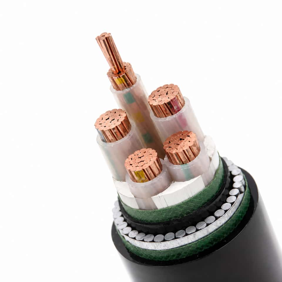
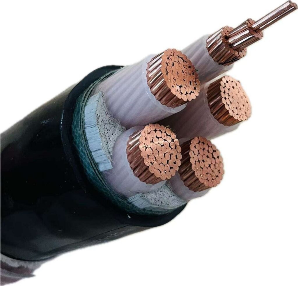
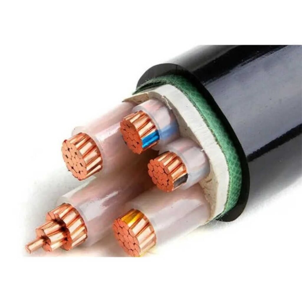
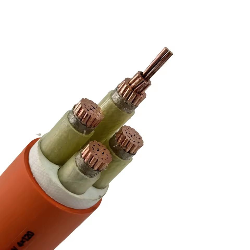
Control wire is a category of insulated electrical conductor used specifically to carry low-current signals, switching commands, and instrumentation data between controllers, sensors, relays, and actuators in industrial and building systems. Conductor sizes typically run from 0.5 mm² to 10 mm², with 1.5 mm² and 2.5 mm² covering the large majority of industrial panel work. Voltage ratings generally fall between 300/500 V and 450/750 V. Its construction — flexible stranding, color-coded insulation, tight dimensional tolerances — is optimized for signal integrity and safe, dense termination, not bulk current delivery.
What surprises most engineers who haven’t sourced control wire in volume is how much variation hides inside that simple definition. Insulation material, conductor flexibility class, shielding configuration, temperature rating — each choice changes how the wire performs in a real installation, and getting into the specifics reveals why the same 1.5 mm² designation from two different suppliers can behave quite differently once it’s bundled inside a 400-connection motor control center running in a 45°C ambient.
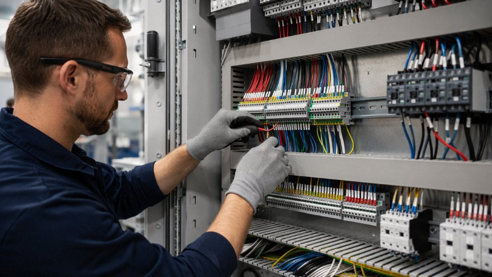
Seven Core Industrial Applications Where Control Wire Is Indispensable
Control wire shows up everywhere once you know what to look for. The applications below aren’t a theoretical survey — they’re the environments where specifying the wrong wire, or skimping on conductor count, creates real downtime.
Motor Control Centers
Inside an MCC cubicle, the wiring density surprises people who haven’t opened one. A single bucket controlling a 15 kW pump can contain 30 to 60 individual control wire terminations — connecting the start/stop push-button station, the auxiliary contacts on the contactor, the overload relay’s trip circuit, and pilot light feedback. Wire routing follows defined wire ducts, usually vertical risers feeding horizontal branches to each device, and the ducts fill faster than engineers expect at the design stage. The de facto standard here is 1.5 mm² stranded copper, and that choice isn’t arbitrary: it’s stiff enough to hold a terminal connection reliably, flexible enough to route through tight duct radius bends, and matches the current capacity needed by coil circuits typically drawing under 5 A. Going down to 0.5 mm² saves almost nothing and creates ferrule crimping headaches at the terminal rail.
PLC and DCS Input/Output Wiring
Discrete I/O wiring is where color-coding stops being a courtesy and becomes an operational necessity. A PLC cabinet with 256 I/O points — not unusual in a mid-size packaging line — can easily require 300 to 400 individual control wire runs connecting limit switches, proximity sensors, and solenoid valve coils out in the field. If your panel builder doesn’t enforce a consistent color scheme and sleeve numbering from day one, tracing a fault at 2 a.m. becomes genuinely painful. Most plants I’ve seen that skipped this step eventually retrofit wire markers during the first major shutdown, which costs more than doing it right initially.
Building Automation and HVAC
Here the conductor count per run drops, but the run lengths stretch considerably. A VAV controller serving a single zone might need a 4-core cable bringing 24 V power plus a modulating signal, while a simple on/off damper actuator runs on 2-core. Under NEC Article 725, Class 2 wiring rules govern most low-voltage control circuits in commercial HVAC — limiting installation to conductors rated for the voltage and separating them from power circuits in conduit. Fire and smoke detector control loops add another layer, often requiring dedicated circuit integrity cable. Skipping that requirement doesn’t just fail inspection; it means your evacuation system may not function in the one scenario it matters.
Machine Tool and Robotics Panels
Flex life is the spec that dominates here. Control wire inside a cable carrier on a CNC machining center or articulated robot arm can complete millions of flex cycles over a machine’s service life. That demands Class 5 or Class 6 fine stranding per IEC 60228, plus an oil-resistant outer jacket — PUR rather than standard PVC is usually the right call in a coolant-heavy environment. Specifying standard fixed-installation wire in a moving cable carrier is one of the more common wiring mistakes on machine retrofits, and the failure mode is insidious: conductors fracture intermittently before they fail completely, causing random faults that look like sensor or controller problems until someone finally does a continuity check under movement.
Power Generation and Substation Control
Switchgear rooms don’t tolerate ordinary wire. Control wire connecting protection relays, trip coils, and annunciator panels must carry fire-resistant (FR) insulation — because if a fault starts a fire, the trip circuits are exactly what you need to keep working. IEC 60331 compliance is the baseline spec in most utility and industrial substation projects. Conductor sizes in this environment typically run 1.5 mm² to 4 mm², with multi-core cables bundled in dedicated control cable trays segregated from power runs.
Fire-resistant control wire maintains circuit integrity under flame exposure long enough for protection relays to complete their trip sequence, which is why FR insulation is mandatory in substation control circuits, not optional.True
IEC 60331 specifies minimum flame-exposure duration (typically 90 minutes at 750°C) during which the circuit must remain functional. In a switchgear fire, tripping upstream breakers depends on these circuits surviving long enough to operate — ordinary PVC insulation fails well before that threshold.
Crane and Hoist Control Circuits
Pendant station wiring, travel limit switch circuits, and load cell feedback all run through cables that are mechanically abused in ways panel wiring never is. Trailing cable variants — with a higher strand count and torsion-resistant jacket — handle the repeated dragging and coiling that pendant cables experience on overhead cranes. Using fixed-installation control wire as a substitute is a maintenance time bomb; jacket cracking and conductor fatigue show up within months rather than years. Load cell feedback circuits are particularly sensitive: signal integrity matters, and any intermittent conductor break in that loop risks incorrect overload readings.
Rail, Transit, and Rolling Stock
Rolling stock brings the most demanding material specifications of any application here. EN 50264 and NEN 3569 govern control wire aboard trains, and the non-negotiable requirement is low-smoke zero-halogen (LSZH) insulation. In a passenger car fire, standard PVC insulation releases hydrogen chloride gas — toxic, corrosive, and dense enough to disorient passengers trying to evacuate. LSZH compounds eliminate that. Temperature ratings for rolling stock control wire often extend to +105°C to handle the under-floor and engine-room zones, and the cables must survive both the vibration profile of rail operation and the temperature cycling between outdoor exposure and heated interiors. Procurement managers sourcing for rail projects who aren’t confirming EN 50264 part classification — EN 50264-2-1, EN 50264-3-1, and so on — are leaving a significant compliance gap.
How to Read a Control Wire Specification: Conductors, Insulation, Shielding, and Jacket
A supplier quotation for control wire can look like alphabet soup until you know what each construction layer actually does in service. Work through it systematically and you’ll catch mismatches before they become expensive re-pulls.
Conductor Material and Cross-Section
Bare copper is the default for most fixed-installation control wiring — adequate in dry panels, perfectly fine for most automation cabinets. Tinned copper makes sense anywhere moisture or mild chemical vapour can reach the terminals: food processing areas, coastal installations, anything with frequent condensation cycles. The tin coating slows oxidation at crimp joints, which matters more than people realise when those joints carry low-level 24 V DC signals where even a few milliohms of added resistance causes nuisance faults.
Stranding class affects flexibility and termination behaviour. Class 1 (solid) is rigid and cheap; it’s fine in a fixed duct but will work-harden and crack if bent repeatedly. Class 5 fine-stranded wire is what you actually want inside a control panel where conductors flex every time a door opens. Class 6 (extra-fine) is for trailing cables and drag-chain applications — moving machine tool axes, robot arms, anything with a defined flex cycle.
Cross-section determines voltage drop on long runs, and this catches people out more often than it should. A quick worked example: a 50-metre 24 V DC control circuit using 1.5 mm² copper conductor (resistance roughly 12.1 Ω/km at 20°C) carries 0.5 A to a solenoid valve. Round-trip length is 100 m. Voltage drop = 0.5 A × (12.1 × 0.1 Ω) ≈ 0.6 V. That’s acceptable. Step down to 0.75 mm² (≈24 Ω/km) on the same run and you’re dropping over 1.2 V — enough to cause marginal PLC input recognition at end-of-line devices, especially at elevated temperature when resistance rises further. On runs beyond 30–40 metres at 24 V DC, always check the drop; don’t just grab whatever reel is on the shelf.
Insulation Materials
PVC insulation covers probably 70–80% of standard industrial control wiring. It’s cheap, widely available, easy to strip, rated to 70°C conductor temperature — completely adequate for a climate-controlled panel room. The limitations show up in cold environments (PVC gets stiff and brittle below roughly -15°C to -20°C depending on the compound) and anywhere aggressive plasticisers or hydraulic oil contact the cable surface.
XLPE handles up to 90°C and resists a broader range of chemicals. It’s the right call for cables routed near motors or in hot duct zones. EPR is the flexible cold-weather choice — it stays pliable well below -40°C and is common in outdoor Nordic installations and refrigeration plant. LSZH (Low Smoke Zero Halogen) is not optional in rail vehicles, road tunnels, offshore platforms, or any enclosed space where evacuating people matters; in a fire, PVC releases hydrogen chloride gas, which is acutely toxic and corrosive to electronics. Specifying LSZH in an open factory hall is unnecessary cost, but skipping it in a cable basement under a public building is a regulatory problem waiting to happen.
Shielding Options
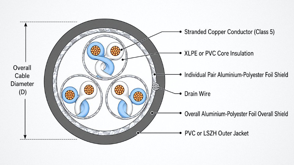
Unshielded control wire is fine in clean electrical environments — a simple motor starter cabinet fed from a clean supply, no VFDs nearby, no radio transmitters. The moment you have variable-frequency drives sharing a cable tray, all bets are off. VFDs generate common-mode noise across a wide frequency range and will inject spurious signals into adjacent unshielded control cores, causing erratic PLC inputs, encoder miscounts, or random valve triggers. An overall aluminium-polyester foil shield with a drain wire handles moderate EMI and is the minimum you should spec for most modern automated cells. Individual pair or triad shielding — each pair wrapped separately — is necessary when you need channel-to-channel isolation, typically in analogue control loops (4–20 mA, 0–10 V) routed alongside digital control cores in the same cable. Braided copper screens offer lower transfer impedance and handle higher-frequency interference better than foil; they’re heavier and more expensive, but standard practice in serious servo drive environments.
The shield is only as good as its termination. A correctly specified shielded cable terminated with the drain wire left floating accomplishes nothing.
Jacket Selection
| Jacket Material | Chemical Resistance | Temperature Range | Mechanical Durability | Relative Cost |
|---|---|---|---|---|
| PVC | Moderate | -20°C to +70°C | Moderate | Low |
| PUR (Polyurethane) | Good (oils, fuels) | -40°C to +80°C | High (abrasion, flex) | Medium–High |
| LSZH | Moderate | -20°C to +80°C | Moderate | Medium |
| Rubber (CPE/CR) | Good | -40°C to +90°C | Good | Medium–High |
PUR is the jacket for machine tools, hydraulic press areas, and anything with cutting fluid or mineral oil splash — standard PVC jacket softens and crazes in those environments within a year or two. Rubber jackets earn their place in foundries and outdoor trailing applications where both low-temperature flexibility and UV resistance matter.
Core Identification and Pair Count
IEC 60446 colour coding handles small core counts — brown, black, grey for the first three, then number printing from core 4 upward in most multi-core cables. In practice, numeric printing on every core from core 1 is more maintenance-friendly in complex panels. When a technician is fault-finding a 48-core control cable at 2 a.m., chasing colour sequences gets tedious fast; sequential numbers with consistent ferrule labelling matching panel drawings is what actually reduces errors and repair time.
Decoding the Cable Designation
A designation like KVVP2-22 breaks down as: K = control cable, V = PVC insulation, V = PVC jacket, P2 = aluminium-polyester tape shield, 22 = steel tape armour. YSLY-JZ (a common European flexible control cable) reads as: Y = PVC insulation, SL = fine-stranded copper (Class 5), Y = PVC jacket, JZ = fine-stranded, numbered cores for control applications. Each letter position is standardised within its national or IEC framework — cross-referencing the originating standard is essential when comparing cables from different suppliers, because a “K” prefix in one system does not carry the same meaning in another.
LSZH insulation produces significantly less toxic and corrosive smoke than PVC in a fireTrue
PVC releases hydrogen chloride (HCl) gas when burned, which is acutely toxic and corrodes nearby electronics. LSZH compounds are formulated to minimise halogen content and smoke density, and this performance difference is verified by IEC 60754 and IEC 61034 test standards.
Control Wire vs. Instrumentation Cable vs. Signal Cable: Where the Boundaries Fall
These three categories sit so close together on a bill of materials that specifiers routinely conflate them — and the consequences range from a wasted budget line to persistent noise faults that take weeks to diagnose.
Instrumentation Cable: Governed by Capacitance and Crosstalk
Instrumentation cable exists specifically to carry low-energy analog signals: 4–20 mA process loops, millivolt-level thermocouple outputs, RTD bridge signals. The governing parameters are individual pair capacitance (typically kept below 100 pF/m, sometimes tighter on long runs) and crosstalk attenuation between adjacent pairs. Why? Because a 12 mV thermocouple signal coupled with even a few millivolts of interference from a neighboring pair produces a temperature reading error that’s invisible at the cable level but shows up as process drift or spurious alarms at the DCS. Individual pair shielding — usually aluminum-polyester foil with a drain wire — is standard precisely because overall braid alone doesn’t isolate pairs from each other.
Control wire doesn’t need any of that. Capacitance per meter is largely irrelevant when you’re switching a 24 V DC coil or carrying a pilot current of a few hundred milliamps. Specifying low-capacitance instrumentation cable for a motor starter control circuit inflates your material cost by roughly 20–40% depending on conductor count and shield construction, with zero functional return.
Substituting instrumentation cable for standard control wire in discrete switching circuits delivers no measurable EMC or signal-integrity benefit.True
Instrumentation cable's low-capacitance, individually shielded pair construction is engineered for millivolt-level analog signals. Discrete control signals at 24 V DC or 120 V AC operate at energy levels orders of magnitude higher, making pair capacitance and crosstalk attenuation irrelevant to circuit function or noise immunity.
Signal Cable: Impedance Becomes the Critical Variable
Signal cable is a broader designation that encompasses both analog transmission and digital data — including fieldbus cables for PROFIBUS DP, DeviceNet, AS-Interface, and similar architectures. What defines these cables at the application level is controlled characteristic impedance, typically 100–150 Ω depending on the protocol. PROFIBUS DP, for instance, requires a nominal 150 Ω cable to prevent reflections that corrupt data frames at higher baud rates. DeviceNet specifies 120 Ω. Violating those impedance specs on a trunk segment longer than roughly 30–50 m tends to produce intermittent communication faults — the kind that appear only when the network is under load and are nearly impossible to replicate on a bench.
Conventional control wire has no controlled impedance whatsoever. It doesn’t need one. Sourcing standard control wire for a PROFIBUS trunk is a specification error that will cause problems in commissioning, full stop.
The Gray Zone: 24 V DC Discrete Sensor Wiring
Here’s where it gets genuinely ambiguous. A proximity sensor output at 24 V DC, switching a PLC digital input — is that a control wire application or an instrumentation cable application? Electrically, either can work. In practice, the decision hinges on the electromagnetic environment and the compliance requirement.
In a cabinet running variable-frequency drives or near high-current bus bars, IEC 61000-4-3 and IEC 61000-4-6 radiated and conducted immunity tests can expose unshielded wiring to field strengths that cause false triggering on fast-switching sensor outputs. A screened cable — even a basic overall-shielded control wire rather than true instrumentation cable — typically solves the problem at modest cost. Individual pair shielding is overkill here unless you’re routing multiple sensor circuits in a dense bundle and crosstalk between them is measurable.
The distinction matters for EMC compliance documentation too. If your machine directive technical file needs to show conducted immunity margins, screened wiring provides a defensible design choice. Unshielded control wire in that environment isn’t automatically wrong, but you’d better have test data to back it up.
Decision Matrix: Matching the Cable Type to the Application
| Parameter | Power Cable | Control Wire | Instrumentation Cable | Signal / Data Cable |
|---|---|---|---|---|
| Current level | High (load current) | Low–medium (pilot/control) | Very low (mA-level signals) | Negligible (data only) |
| Signal type | N/A | Discrete on/off | Analog (4–20 mA, mV) | Analog + digital / fieldbus |
| Noise sensitivity | Low | Low–moderate | High | Protocol-dependent |
| Shielding | Rarely needed | Optional (environment-driven) | Individual pair shields standard | Overall or paired shield, impedance-controlled |
| Typical voltage | 600 V–35 kV+ | 300/500 V to 450/750 V | 300/500 V | Per protocol spec |
| Impedance control | None | None | None | 100–150 Ω typical |
| Cost relative to control wire | Lower–similar | Baseline | 20–40% higher | Varies; often higher |
The table won’t make the decision for you in every case, but it surfaces the governing variable quickly. When the critical parameter is current and voltage, you’re in power cable territory. When it’s millivolt-level accuracy, you’re in instrumentation. When it’s bus timing and reflections, you need a specified data cable. Control wire is what everything else turns out to be — which is why it covers the widest range of actual plant wiring.
International Standards and Approvals That Govern Control Wire Selection
Getting the standard right before you cut the purchase order is not a formality — specifying the wrong approval can mean rework at incoming inspection, rejected installations during commissioning audits, or, in the worst cases, insurance voidance after an incident. The standards landscape for control wire is genuinely fragmented across regions, and the overlaps are messier than any certification body will openly admit.
IEC 60227 and IEC 60245: The Baseline Framework
IEC 60227 covers PVC-insulated cables for rated voltages up to 450/750 V, and it is where most industrial control wire sits. Sub-parts 3 and 5 are the ones that matter most for control wiring: part 3 addresses fixed installation cables, and part 5 covers flexible cables. The type-designation codes embedded in IEC 60227 — that string of letters like H05VV-F or H07V-U — are not arbitrary. Each character encodes harmonisation status, voltage class, insulation compound, core arrangement, and whether the construction is rigid or flexible. Once you can decode those, a European datasheet stops being opaque.
IEC 60245 handles rubber-insulated variants, which come up in high-temperature zones around furnaces or compressor decks where PVC softens and creeps. These tend to be specified more selectively; most general control panel wiring stays within the 60227 family.
Both IEC documents map directly into EU harmonised standards through CENELEC, so a cable designated to IEC 60227 will generally satisfy HD 21 in Germany, NF C 32-201 in France, and similar national adoptions. In the Middle East — UAE, Saudi Arabia, Qatar — the controlling authorities have largely aligned with IEC, but verification against local ESMA or SASO requirements is still worth a line item in your pre-procurement checklist, since enforcement rigour varies by project type and end-client. Southeast Asian markets are similar: Singapore’s SS 299 references IEC 60227 closely, while countries like Vietnam and Indonesia use IEC as the technical basis but layer on local product registration requirements for imported cable.
UL 508A and NFPA 79: North American Panel Wiring Requirements
For any control panel destined for North America, UL 508A is the governing standard for enclosed industrial control panels, and NFPA 79 covers the broader electrical standard for industrial machinery. Both impose specific requirements on control wire that are stricter in some respects than IEC equivalents. Wire inside a panel enclosure typically must be rated 60°C minimum at 600 V, with 90°C ratings preferred where ambient temperatures inside the enclosure can climb — and in a sealed steel enclosure in a hot press shop, ambient temperatures of 50–60°C inside the cabinet are not unusual. NFPA 79 (Section 12) mandates that conductors be listed and marked, requires minimum 0.75 mm² for control circuits in most applications, and specifies colour coding that differs from European convention: in North America, black is a line conductor, while IEC practice uses brown.
Gauge and insulation markings on the wire itself must be legible at regular intervals — UL requires marking every 610 mm (24 inches) — and the UL listing mark must correspond to the actual wire construction, not just the compound family. Substituting a non-listed cable because it looks equivalent is one of the more common panel-shop shortcuts that comes back badly during UL field inspection.
Derating for Bundled Runs: IEC 60364-5-52
IEC 60364-5-52 governs wiring system installation methods and sets out current-carrying capacity tables — and the derating factors for grouped cables are the part most often ignored during design. When control wire runs are bundled tightly in cable trays or enclosed ducts, heat accumulates and rated current drops, sometimes significantly.
| Installation Condition | Typical Correction Factor Range | Key Dependency |
|---|---|---|
| Single cable, free air | 1.00 (baseline) | Reference condition |
| 2–3 cables grouped in tray | 0.70–0.85 | Spacing and tray fill |
| 4–6 cables grouped | 0.60–0.75 | Bundle diameter, airflow |
| Enclosed conduit, >6 cables | 0.50–0.65 | Conduit fill ratio |
| Ambient temperature 45°C | 0.87 (from 30°C base, PVC) | Insulation Tmax rating |
| Ambient temperature 55°C | 0.71 (from 30°C base, PVC) | Same dependency |
In practice, control wire rarely runs anywhere near its thermal limit — the loads are small — but in dense cable duct systems where power cables and control runs share the same containment, the grouping factor still needs to be checked and documented for audit purposes.
Flame and Fire Performance: Getting the Zone Right
This is where specification errors get expensive. IEC 60332-1 tests a single wire for vertical flame propagation — it is the minimum bar and applies to almost any listed cable. IEC 60332-3 tests a bunch of cables simultaneously, which is the relevant standard for cables installed in open trays, cable ladders, or any route where a fire could propagate along the run. For building penetrations, risers, and enclosed ducts in occupied structures, you usually need IEC 60332-3 Category C or better, combined with IEC 60754 halogen-free requirements and IEC 61034 low-smoke performance.
A cable marked IEC 60332-1 compliant is suitable for use in bunched cable tray installations without further testingFalse
IEC 60332-1 only validates single-wire flame performance. Bunched or tray installations require IEC 60332-3 compliance, which tests flame propagation across a group of cables simultaneously — a significantly more demanding test.
The combination required by zone looks roughly like this: open outdoor cable tray can often be satisfied with IEC 60332-3-22 alone; enclosed cable ducts inside a facility typically require 60332-3 plus 60754-2 (halogen acid gas); building risers and public infrastructure projects in Europe and the Gulf frequently demand the full stack — 60332-3, 60754-2, and 61034-2 smoke density. The insulation and jacket compounds drive which combination is achievable, and PVC cannot satisfy halogen-free requirements, so substituting LSZH (low smoke zero halogen) compounds changes the cost, sometimes by 20–40% depending on conductor count and market pricing at the time.
Marine, Offshore, and Rail Approvals
These sectors demand type approval beyond standard IEC compliance, and the approval process itself takes time — typically months, not weeks. IEC 60092 series covers marine electrical installations, including specific sub-parts for cable construction and installation on ships. Offshore platforms require DNV or Lloyd’s Register type approval, which involves factory surveillance audits and sample testing at approved laboratories; specifying an unapproved cable and expecting equivalency arguments to hold at the platform operator level rarely works.
Rail applications fall under EN 50264 (rolling stock cables) and EN 50306, with fire performance requirements that are among the most demanding of any sector — EN 45545 hazard levels layer on top for passenger vehicles. Jinda holds multiple international certifications covering these sectors, which shortens the qualification path significantly on projects where approval documentation is part of the tender submission.
CE, RoHS, and REACH
CE marking for cable exported to the European Union falls under the Construction Products Regulation (CPR), specifically performance classes defined in EN 13501-6 for fire performance — Eca, Dca, Cca, and so on. These map loosely to the IEC 60332 series but are not identical, and a cable with IEC 60332-3 documentation still needs a Declaration of Performance under CPR for EU construction projects.
RoHS restricts specific hazardous substances — lead, cadmium, hexavalent chromium, certain phthalate plasticisers — in electrical equipment placed on the EU market. Most modern LSZH and PVC compounds from reputable manufacturers are already compliant, but the documentation trail matters: buyers should request RoHS Declaration of Conformity explicitly, not assume it. REACH adds a further layer around substances of very high concern (SVHCs) in cable compounds, and while cable itself is not an article under REACH in the same way a moulded part is, the compound supply chain should be traceable for any project with rigorous environmental reporting requirements.
Getting all of this aligned before order placement — not during expediting — is what separates a clean project closeout from a very stressful one.
Installation Best Practices: Routing, Segregation, Termination, and Testing Control Wire
Getting the cable specification right is only half the job. Poor installation practice — wrong tray routing, skipped megger tests, improperly sized ferrules — causes more field failures than bad wire ever does. The points below are the ones experienced panel builders and commissioning engineers have learned to enforce before energizing anything.
Cable Segregation: Keep AC Control, DC Control, and Analog Wiring Apart
NFPA 79 clause 13.5 is explicit: AC and DC control conductors should not share a raceway unless separation is maintained or shielded cable is used. IEC 60364-4-44 sets crosstalk limits that translate, in practice, to a minimum physical separation of roughly 150–200 mm between unshielded AC control runs and analog signal wiring, though the exact distance depends on voltage levels, cable length, and whether the analog circuit is current-loop (4–20 mA) or high-impedance voltage type. In my experience, the analog signals suffer most — a 24 V DC switching circuit toggling rapidly next to a 4–20 mA loop can inject enough noise to shift a PLC analog input reading by several percent, which on a flow control loop translates directly to process drift or nuisance alarms.
Use separate trays, or at minimum separate compartments within a divided tray. Color-coding the cables at source (yellow for DC control, orange or grey for AC control) helps, but it doesn’t replace physical segregation — it just makes auditing faster.
Bend Radius: Where Insulation Failures Start
The general rule for fixed installations is 6–8× the overall cable diameter; for flexible or moving applications, 10–12×. These aren’t arbitrary — they reflect the strain mechanics of the conductor strands and the elasticity limits of PVC or XLPE insulation. Violate the bend radius on a 1.5 mm² multi-core control cable pulling it around a panel edge, and the damage is invisible on day one. Six months later, with thermal cycling, you get insulation micro-cracking at the bend point, intermittent ground faults, and a maintenance technician spending a shift chasing a phantom fault with a megger and a wiring diagram.
At conduit entries and panel knockouts, use proper bushings. Pulling wire over a bare metal edge is one of those habits that is common and consistently costs plants time later.
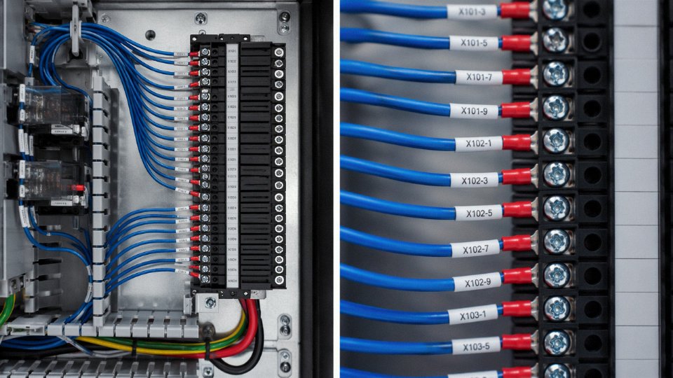
Termination: Ferrules Are Not Optional for Stranded Wire
Stranded conductors in screw-clamp terminals will fan out under tightening torque. Individual strands escape the terminal over time, creating high-resistance connections that heat up under load — or worse, strand migration that causes a short to an adjacent terminal. Ferrule crimping to DIN 46228 solves this. The ferrule consolidates the strands and presents a uniform cylindrical contact surface to the terminal.
Sizing matters more than most people bother to check. A ferrule rated for 1.5 mm² on a 2.5 mm² conductor will not fully capture the strands. Match ferrule cross-section exactly to conductor cross-section, and match ferrule length to the terminal insertion depth — most European-style terminals are designed for 8–10 mm ferrule length. Spring-clamp terminals (Phoenix, Wago, and similar) are more forgiving of strand spreading and can accept ferrule or non-ferrule terminations, but ferrules still improve consistency in high-vibration environments.
Labeling: Match the Drawing Before the Panel Is Energized
IEC 60445 governs terminal identification and wire marking. In practice, this means every conductor gets a sleeve label or clip-on marker at both ends — not just one end — and those labels must match the wiring diagram numbering before a commissioning engineer signs off. Heat-shrink sleeve labels printed with a dedicated label printer are more durable than adhesive clip-ons in environments with oil mist or cleaning solvents. The common mistake is labeling one end during installation and assuming the other end is obvious. It rarely is, especially two years later when someone else is fault-finding.
Insulation Resistance Testing Before Commissioning
For 300/500 V rated control wire, the standard megger test voltage is 500 V DC. Minimum acceptable insulation resistance is typically in the range of 1 MΩ per 100 m of run, though many plants set a site-specific floor of 10–20 MΩ as a quality gate. A reading below 1 MΩ usually points to insulation damage at a bend point, moisture ingress at a conduit entry, or a pinched conductor. Isolate by disconnecting at the far end and testing each core individually against the screen or armor — this narrows the fault to a specific conductor rather than leaving you chasing the whole bundle.
Sealing Spare Cores: A Step That Gets Skipped
Any unused conductors must be sealed at both ends with insulating end caps. In humid environments — coastal plants, food processing areas, anywhere with frequent washdown — unsealed spare cores wick moisture by capillary action along the conductor stranding, gradually reducing insulation resistance across the entire cable. They also create capacitive coupling paths that can introduce noise into adjacent active circuits. It takes about thirty seconds per core to fit an end cap. Not doing it is one of those small omissions that becomes a genuine problem by year two.
Ferrule crimping to DIN 46228 reduces terminal resistance and prevents strand migration in screw-clamp terminals, improving long-term connection reliability in industrial control panels.True
This is well-established practice supported by DIN 46228 standard geometry requirements and widely documented in IEC 60947-7-1 terminal testing data, where unforrected stranded conductors demonstrate measurably higher contact resistance under thermal cycling.
Specifying Control Wire for Harsh Environments: Oil, Heat, Cold, Chemical, and Outdoor Exposure
Standard PVC control wire is a workhorse — cheap, flexible, easy to terminate, and perfectly adequate in a climate-controlled panel room. Take it outside that comfort zone, and the failures tend to be slow, insidious, and expensive. Insulation that looks intact will have lost 40–60% of its elongation-at-break. A jacket that feels fine at room temperature becomes a rigid tube at -20°C and cracks on the first cable-tie torque.
The procurement decision tree for harsh environments is really a sequence of elimination: rule out what will fail first, then weigh cost against service life.
High-Temperature Environments: Furnaces, Foundries, and Engine Rooms
PVC is typically rated to 70°C continuous on the conductor surface. Push past that — which happens routinely near furnace control panels, engine room cabling runs, and anywhere heat radiates from adjacent power conductors — and the plasticiser migrates out over time, leaving a brittle shell.
The transition ladder runs roughly like this:
| Conductor Surface Temp | Recommended Insulation | Typical Standard Reference |
|---|---|---|
| Up to 70°C continuous | Standard PVC | IEC 60227 |
| 70°C – 150°C | XLPE or EPR | IEC 60502, UL 44 |
| 150°C – 250°C | Silicone rubber | IEC 60245 |
| Above 250°C | Mineral-insulated (MI) | IEC 60702 |
XLPE doesn’t plasticise — it’s cross-linked, so it holds mechanical properties at elevated temperature far better than PVC. Silicone is the right answer for intermittent high-heat zones, like inside a kiln control enclosure where ambient can spike to 180°C. MI cable is a different world entirely: copper sheath, compacted magnesium oxide filling, essentially indestructible in fire — but stiff, expensive, and requires specialist termination kits. Don’t over-specify it unless you genuinely need it; the termination labour cost alone can surprise a project budget.
Low-Temperature and Arctic Outdoor Installations
Standard PVC compounds become brittle somewhere in the range of -10°C to -15°C. For outdoor switchgear yards in northern climates, wind farm nacelle wiring, or any installation where cables get handled in winter, this matters during installation more than during operation — a cable pulled through a tray at -25°C with standard PVC jacket will crack at the first bend.
Specify PUR (polyurethane) jacket or a cold-rated PVC compound explicitly rated to -40°C. The datasheet should show a cold-bend test result per IEC 60811-506 at the rated minimum temperature. If you can’t find that figure, assume it isn’t rated.
Oil and Hydraulic Fluid Exposure
PVC swells in prolonged contact with petroleum-based oils. The effect is gradual — the jacket softens, loses abrasion resistance, and eventually the insulation underneath is compromised. In machine tool electrical cabinets and hydraulic power unit enclosures, this is a common cause of intermittent faults that are genuinely difficult to trace.
The fix is PUR jacket or oil-resistant PVC specified to Type 2 PVC per IEC 60811. Here’s the operational warning: resistance data is oil-type specific. A cable rated for mineral hydraulic oil may not hold up in synthetic ester or water-glycol hydraulic fluids. Always request immersion test data against your actual fluid, not just a generic “oil resistant” claim.
PUR-jacketed control wire maintains dimensional stability after 168 hours of immersion in mineral oil per IEC 60811-2-1 test conditions.True
PUR is widely documented in IEC 60811 test data to show negligible swell and mass change in mineral oil immersion tests compared to standard PVC, which can exceed 10% mass increase under the same conditions.
Chemical and Solvent Exposure in Process Plants
This is where the material trade-offs get genuinely messy. LSZH (low-smoke zero-halogen) compounds generally outperform standard PVC against dilute acids and alkalis — useful in battery rooms and chemical dosing areas. Hydrocarbons flip the picture: many LSZH formulations absorb solvents and swell more than PVC.
A rough cross-reference for common exposures:
| Chemical Class | Standard PVC | LSZH | PUR |
|---|---|---|---|
| Dilute acids (pH > 2) | Moderate | Good | Good |
| Alkalis | Good | Good | Good |
| Aliphatic hydrocarbons | Poor | Poor | Good |
| Ketones / esters | Poor | Poor | Moderate |
| Chlorinated solvents | Poor | Poor | Poor |
For chlorinated solvents, honestly, route in conduit and accept that you’ll be replacing the cable periodically. No jacket material is truly robust there.
UV and Ozone Resistance for Outdoor Above-Ground Routing
Unprotected standard PVC in direct sunlight typically shows surface crazing within 2–5 years, depending on UV intensity and temperature cycling. The mechanism is photo-oxidation, and once it starts you get micro-cracking that lets moisture wick into the insulation.
UV-stabilised PVC or XLPE with carbon-black compounding is the practical answer for most outdoor above-ground cable trays. On datasheets, look for explicit UV resistance testing to IEC 60068-2-5 or equivalent, with test duration and irradiance conditions stated. “UV resistant” without test data is marketing.
Conduit protection is a legitimate alternative if cable length is short and conduit fill calculations allow — it avoids material upcharge and makes future replacement straightforward.
Mechanical Abuse: Vibration, Pull-Through, and Flex Cycles
Control wire inside flexible conduit on machine tools lives a hard life. Vibration fretting, repeated pull-through during maintenance, and occasional sharp bends at conduit entry points are all in play.
Class 5 or Class 6 stranding matters here — finer strands bend without work-hardening at the rate that coarser conductors do. PUR jacket hardness in the Shore A 85–95 range gives a useful balance of abrasion resistance without becoming so stiff that it resists flexing. Specify abrasion resistance to EN 50395 or equivalent and ask for the number of flex cycles at the rated bend radius — 10 million cycles at 7.5× cable diameter is a reasonable baseline for a machine tool application expecting a 10-year service life without cable replacement.
In practice, the cables that fail early in this environment are usually ones someone specified by price alone, or pulled from the wrong reel because the right one wasn’t on the shelf that day.
How to Calculate the Right Control Wire Size for Your Project: A Step-by-Step Procurement Guide
Getting the wire size wrong in a control system costs you in one of two directions — either you’re running undersized conductors that drop voltage across a 60-meter run until a PLC input stops registering, or you’ve over-specified 4 mm² for a circuit that peaks at 0.2 A and you’ve just wasted budget and tray space. Neither is acceptable on a real project. Here’s how to work through it properly.
Step 1 — Determine the Control Circuit Current
Start with the actual device current, not a guess. Most 24 V DC PLC I/O circuits draw somewhere between 0.1 A and 0.5 A per core depending on the output module type and the load — a standard solenoid valve coil typically sits in the 0.2–0.4 A range, while a relay coil might pull as little as 0.05 A. For 230 V AC contactor coil circuits, expect 0.1–1.0 A at seal-in; inrush at pick-up can be 5–10× that for a fraction of a second, which matters for wire heating in tight bundles.
| Device Type | Typical Current Range | Voltage |
|---|---|---|
| PLC digital output (sourcing) | 0.1 – 0.5 A | 24 V DC |
| Solenoid valve coil | 0.2 – 0.8 A | 24 V DC or 230 V AC |
| Contactor coil (seal-in) | 0.1 – 1.0 A | 230 V AC |
| Indicator lamp / HMI signal | 0.05 – 0.15 A | 24 V DC |
| Motor thermistor circuit | < 0.01 A | 5–10 V DC |
Always pull the device datasheet. Manufacturer-rated coil currents vary more than you’d expect between brands.
Step 2 — Calculate Voltage Drop
Use the standard formula:
VD = (2 × L × I × ρ) / A
Where L is one-way cable length in meters, I is current in amperes, ρ is copper resistivity (0.0175 Ω·mm²/m), and A is conductor cross-section in mm².
Concrete example: a 24 V DC solenoid valve 75 meters from the panel, drawing 0.4 A, wired on 1.5 mm² conductor.
VD = (2 × 75 × 0.4 × 0.0175) / 1.5 = 0.70 V
That’s about 2.9% of 24 V — acceptable for most solenoids, which typically tolerate ±10% supply variation. Drop the same circuit to 0.75 mm² and you’re at 1.4 V drop, nearly 6%, which is where valve manufacturers start hedging their reliability guarantees. On a 75-meter run, 1.5 mm² is the right call; on a 150-meter run, you’d step up to 2.5 mm².
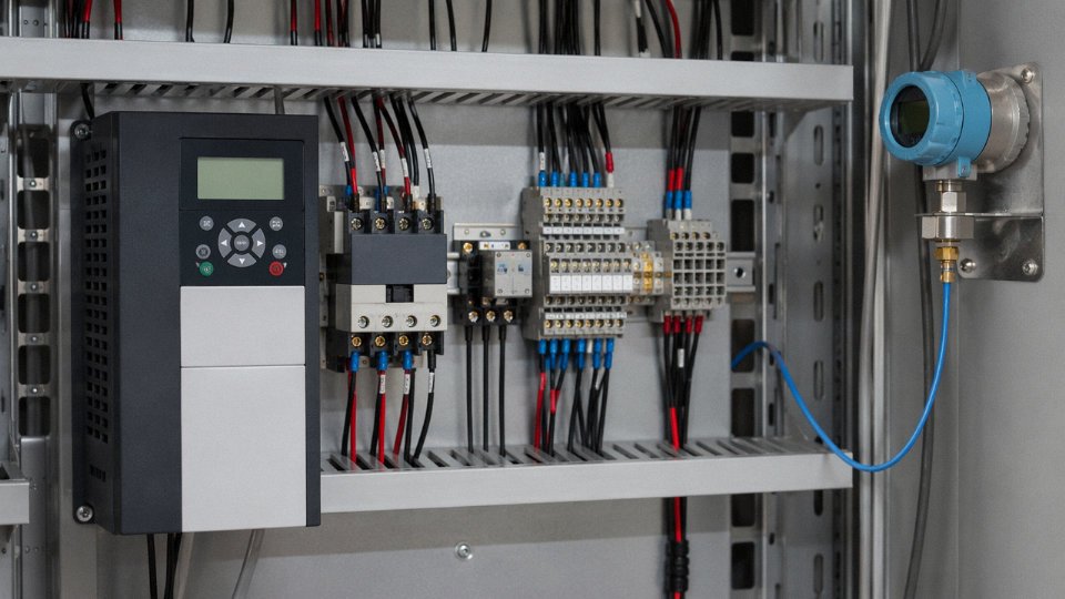
Step 3 — Apply Derating Factors for Grouped Cables
This is the step most procurement engineers skip, and it’s the one that causes real problems. IEC 60364-5-52 Table B.52.17 gives grouping correction factors for cables installed together in trays or conduit. A bundle of 20 control cables may carry a derating factor of roughly 0.38 — meaning a conductor rated for 13 A in free air can only be relied upon for around 5 A in that bundle. In practice, control circuits rarely run at sustained full load, so many engineers accept some analytical risk here, but in high-ambient installations (a foundry in summer, say) grouped derating deserves serious attention rather than hand-waving.
IEC 60364-5-52 Table B.52.17 provides grouping derating factors that can reduce allowable current capacity to below 40% of free-air ratings for densely bundled cable installations.True
The standard's grouping correction factors for installation method and number of circuits are well-established; a factor of 0.38 for 20 or more grouped cables is consistent with published IEC 60364-5-52 tabulated values.
Step 4 — Select Core Count
Count your discrete I/O points from the wiring diagram, then add 10–20% spare cores. Spare cores sound like waste until a site engineer has to pull a new cable through a filled conduit six months after commissioning because a sensor was added. That retrofit cost typically runs several times the original cable cost.
The single-core-versus-multi-core decision depends on installation density and how the plant maintains wiring. Dense panel builds with clear labeling often use multi-core control cable — 12-core or 19-core — to reduce conduit fill and simplify termination. Distributed I/O installations where field devices are wired individually usually favor single-core runs. Neither approach is universally right.
Step 5 — Estimate Cable Quantities with a Waste Factor
Measured route length is never actual cable consumption. Add 10% for panel loops and termination tails, 15% for cable tray runs with bends and offsets, and 20% for drag-chain applications where the cable must flex continuously and you’ll need future slack. On a large project covering thousands of meters, under-ordering by even 8% creates a procurement delay that can hold up commissioning. Jinda’s technical team routinely supports bill-of-materials review on complex projects, cross-checking cable schedules against route drawings before orders are placed — this catches the obvious gaps before they become site problems.
Step 6 — Document the Specification in a Cable Schedule
A cable schedule is not optional on any project with more than a handful of runs. At minimum, each row should carry: tag number, from-location (panel tag and terminal number), to-location (field device tag), conductor cross-section in mm², core count, insulation and jacket material (e.g., PVC/PVC, XLPE/LSZH), voltage rating (300/500 V or 450/750 V), screen requirement (yes/no, and screen type), applicable approval standard (IEC, UL, or project-specific), and estimated installed length. Get those fields agreed with the engineering team before procurement starts — changing the jacket specification after 5,000 meters have been ordered is a conversation nobody wants to have.
Frequently Asked Questions About Control Wire
Can I use power cable instead of control wire to save cost?
Short answer: you can, but you’ll regret it at the panel-build stage. Power cable is sized for load currents that control circuits rarely approach — substituting it means you’re pulling 4 mm² or 6 mm² conductors through the same terminal blocks designed for 1.5 mm². Ferrule crimping becomes awkward, cable duct fills up faster than planned, and the panel ends up heavier and harder to trace during commissioning. On a small panel with a dozen circuits, the difference feels minor. Across a large automation cabinet with 200–400 individual connections, the aggregate cost of extra duct space, larger enclosures, and labor time usually exceeds whatever you thought you saved on cable unit price. Multi-core control wire — say, a 12-core KVV — also lets you pull one cable where you’d otherwise need multiple power cables, which matters when tray space is tight.
What is the maximum length of a control wire run before voltage drop becomes a problem?
It depends entirely on supply voltage, load current, and conductor size — there’s no single safe answer. As a working example: a 24 V DC control circuit drawing 0.5 A through 1.5 mm² copper conductor hits the commonly accepted 5% voltage drop limit at roughly 257 meters of loop length. Drop below that threshold and your PLC input or relay coil may see less than 22.8 V, which is inside the dropout risk zone for some devices. Longer runs need either a larger conductor (move to 2.5 mm²) or a higher supply voltage (switch to 48 V DC or 110 V AC). The calculation is straightforward: voltage drop = (2 × L × I) / (conductivity × A), where L is one-way run length in meters. Run it before you finalize the cable schedule, not after.
Do I need shielded control wire inside a control panel?
In a panel running relay logic with no variable-frequency drives or servo controllers, shielding is generally unnecessary and adds cost without benefit. But the moment you introduce a VFD, a servo drive, or any high-frequency switching device into the same enclosure — or even an adjacent one sharing the same cable tray — the situation changes. EMI from drive output switching can couple into unshielded control conductors running nearby and trigger false PLC inputs. I’ve seen a plant chase an intermittent conveyor fault for three days before someone realized the control wire was sharing a duct with the VFD output cable. Use shielded KVVP inside panels with drives, keep shield drain wires grounded at one end only to avoid ground loops, and maintain physical separation where possible.
What is the difference between KVVP and KVV cable designations?
Both follow the Chinese GB/T 9330 standard for PVC-insulated control cables. The letter designations break down systematically: K = control cable, V = PVC insulation, V = PVC outer jacket. KVVP adds a P suffix — P stands for a copper wire braid screen applied over the assembled cores before the outer jacket. So KVV is unshielded, KVVP is shielded. You’ll also see variants like KVVR (R = flexible stranded conductors for applications needing some movement) or KVVRP (flexible and shielded). Jinda manufactures the full range across these designations, which matters when a single project spec calls for a mix of shielded and unshielded cores in different sections of the same installation.
KVV and KVVP control cables manufactured to GB/T 9330 carry standardized letter designations where each character corresponds to a defined construction element, allowing engineers to decode the full cable construction directly from the type code.True
The GB/T 9330 standard for PVC-insulated control cables uses a structured alphanumeric designation system where K=control cable, V=PVC insulation, V=PVC jacket, P=braided copper shield, R=flexible conductor — this is verifiable in the standard text and consistent across Chinese cable manufacturers.
How many cores can a control cable have?
Standard catalog ranges typically run from 2 cores up to 61 cores — though 4, 7, 10, 12, 19, 24, and 37 cores cover the vast majority of real installations. Jinda’s range follows this spread. Choosing between one large multi-core cable and several smaller ones isn’t purely a count question. Route length matters: pulling a single 37-core cable 150 meters is usually easier than managing six 6-core cables on the same route. Tray space and bend radius matter too. And leave yourself spare cores — roughly 10–15% extra is common practice, because retrofitting a cable to add one circuit to a distant panel is expensive.
What is the service life of control wire in a typical industrial installation?
In a clean, temperature-controlled indoor panel environment with correct installation, well-specified PVC control wire routinely lasts 25–40 years. The insulation degrades slowly, terminations stay stable, and there’s no mechanical stress. Outdoor installations, high-heat environments above 70°C continuous, or any application involving repeated flexing — think pendant control stations on cranes or cable track systems — compress that figure sharply. Expect 5–15 years in those conditions, and plan for inspection cycles. Specification to environment is the single biggest determinant of service life, more than brand or price tier.
Can control wire be used outdoors direct-buried?
Standard unarmored control wire is not rated for direct burial and shouldn’t be installed that way. Soil moisture, ground movement, and mechanical damage from stones or machinery will eventually breach the jacket and insulation. The correct approach is either to route unarmored control wire through rigid conduit (PVC or galvanized steel, depending on soil chemistry) or specify armored control cable — steel wire armored (SWA) or steel tape armored (STA) — with an outer PVC or HDPE oversheath rated for soil contact. Jinda’s armored control cable range covers both SWA and STA configurations with UV-stabilized or oil-resistant oversheaths for direct-burial and outdoor overhead applications. For runs in aggressive soils with high chloride or acidic content, ask specifically about the oversheath compound rating — not all “outdoor” oversheaths are chemically equivalent.
Why Long-Term Supply Partnership Matters for Control Wire Projects: Jinda’s Global Manufacturing Capability
Control wire procurement looks straightforward on paper — until a project schedule slips because a batch arrives with inconsistent insulation thickness, or a customs clearance stalls because the test certificate doesn’t match the format the client’s engineer specified. At that point, the difference between a transactional supplier and a genuine manufacturing partner becomes very real, very fast.
Scale That Actually Moves the Needle for EPC Contractors
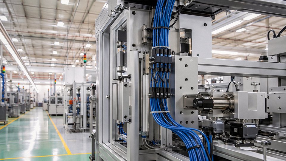
Jinda operates five production bases across China with a combined manufacturing footprint of roughly 470,000 m². That scale isn’t just a number to put in a brochure — it means the capacity to run multiple large production orders in parallel without the usual queue that plagues mid-size cable houses. For an EPC contractor managing a power plant or water treatment facility with a hard commissioning deadline, the ability to call in a substantial cable order and get a confirmed delivery window — not a vague estimate — changes how you structure your procurement schedule. Large automated facilities can consume thousands of meters of control wire in a single installation phase; a supplier that runs short and asks for a four-week extension on a supplementary coil can derail a whole electrical fit-out sequence.
In-House Testing: Batch Traceability That Holds Up at Customs and on Site
Jinda’s laboratories run the tests that actually matter for project documentation: conductor resistance per IEC 60228, insulation resistance, AC voltage withstand, flame performance to IEC 60332 series, and environmental aging. Each production batch carries traceable test records, which means your project QA file has real data attached to it rather than a generic declaration. This matters more than most buyers realize. When a client’s engineer in the Middle East asks for a test report that maps to a specific IEC edition, or when a customs authority in Southeast Asia requires a CCC certificate alongside the commercial invoice, having that paperwork generated in-house — not chased from a third-party lab after the fact — keeps your shipment moving.
Jinda holds CE, CCC, and ISO 9001 certifications and has exported to more than 50 countries since 1987.True
These certifications and the export track record are stated corporate facts consistent with Jinda's established manufacturing history and documented international sales activity.
The certification portfolio — CE, CCC, ISO 9001, plus product-specific approvals — covers the compliance requirements you’ll encounter across the EU, Gulf states, Southeast Asia, Africa, and South America. Thirty-plus years of export experience across 50-plus countries does tend to smooth out the documentation surprises that catch newer exporters off guard.
Specification Translation: More Useful Than It Sounds
One underappreciated differentiator is engineering support at the specification stage. Projects sourced globally often carry mixed-standard requirements — a panel built to UL 508A might need to be re-documented to IEC equivalents for a client in a market that doesn’t recognize UL. Jinda’s engineering team can map those requirements and confirm which product in their range satisfies both, saving the specifying engineer from having to do that cross-reference alone or risk getting it wrong and ordering non-compliant cable.
Customization Without the Premium Lead Time
Non-standard core counts, customer-specific color sequences, private-label drum marking, and special jacket compounds — LSZH grades, oil-resistant formulations, UV-stabilized variants — are handled through Jinda’s integrated R&D and production structure rather than outsourced. Custom drum lengths for specific reel-off requirements in panel shops are available without the minimum-order premiums that smaller manufacturers typically impose.
Supply Continuity for Multi-Year Programs
OEMs and EPC firms running multi-year programs need more than a good first shipment. Jinda supports blanket purchase agreements with scheduled releases, safety-stock programs, and dedicated account management so that when Phase 2 of a facility starts 18 months after Phase 1, the cable specification, color coding, and marking are consistent — not subtly different because a different production run used a slightly varied compound.
Contact Jinda’s international sales team to request a technical consultation or project quotation tailored to your specific control wire requirements and delivery schedule.